GEMMASTA GS10 User manual

GEMMASTA
GS10
Power Feed
10” Slab Saw
Operating Instructions


MODEL GS10
GEMMASTA 10” POWER FEED SAW
INSTRUCTIONS FOR USE
PlacetheGS10sawonafirmstablebenchorframe.
Fitthe10”bladeontotheshaft,putontheflangeandnut,andtightenthe
nutsecurely.Toaccessthebladeshaftyouwillneedtohavetheslidingvice
tablefullyforward(SeeOperatingInstructionsbelowonhowtodothis).
SlidethebladeguidebackuntilthebladeisintheUsection.Adjustthewhite
padsuntiltheyarejusttouchingtheblade.Thepadsshouldsitapproximately
3-5mmbehindthecuttingedgeoftheblade.SeeFIG.5.
Fillthesumpwithyourcoolantuntilbetweenthelinesonthecoolantlevel
indicator.SeeFIG.4.
Plugthethreepinplugintoanappropriateoutlet,protectedbyaRCDcircuit
breaker.
YourGS10sawisnowreadytouse.
OPERATING INSTRUCTIONS
Unscrewthelockingthumbscrewonthehalfnutsandreleasethecatchto
allowthehalfnutstospringapart(SeeFIG.3).Movetheslidingvicetable
towardsthefrontofthemachine.
Holdthematerialtobeslicedsecurelyinthevice,usingthewing-nutsonthe
topofthevice,thenadjusttheLevellingScrew(SeeFIG.1),untilthetopvice
plateislevel.Tightenthewing-nutsagaintoensurethematerialissecurelt
heldinthevice.Therockshouldnotbehigherthan3½”.Iftherockisan
irregularshape,eithergrindsomeflatsontoitsothatthevicecangrip
securely,orpackwithwoodenwedges.Iftherockisnotheldsecurelyitcan
moveduringthecutanddamagetheblade.
LoosentheBackWing-NutandtheFrontLockingKnob(calledtheFront
ScrewLeverinFIG.1)andwindthecrossfeedhandle(SlabThicknessScrew
Handle)tosetthethicknessoftheslab.TightentheFrontLockingKnoband
thentheBackWing-Nuttolocktheviceinplace.Movetheslidingvicetable
towardsthebladeuntiltherockisalmosttouchingtheblade.
Lockthehalfnutsandlowerthelid.TurnontheGS10andallowthepower
feedtopushthestoneintothebladeuntilthecutisfinishedandspecimenin
thevicehaspassedthecuttingedgeoftheblade.Theslabwillfallontothe
lefthandsideoftheslidingtable.TurnofftheGS10.TheGS10LeadScrew
hasasafetyreliefsothatifvicewillonlyfeedtoacertainpointandthen
stop.ThisensuresthattheLeadScrew,ortheGearbox,doesnotget
damaged.

Cont……/2 -2-
Whenthecutiscompleteunlockthehalfnutsandmovethevicetablefully
forward.LoosentheBackWing-NutandtheFrontLockingKnobandwindin
theCrossfeedHandleuntilyougettherequiredthicknessofrockslice.Move
theslidingvicetableuptotheblade,lockthehalfnuts,lowerthelidandstart
thecutagain.
PULLEY SPEEDS
TheGS10sawhasafixedbladespeed.Thebladespeedissettogivethe
mosteconomicalcuttingwithMKdiamondsawbladesandthesintered
continuousrimdiamondsawbladesandefficientcuttingfortheDiatrenn
diamondsawblades.
Thepowerfeedpulleyshavetwospeeds(SeeFIG.2).Theslowspeed,about
6mmperminute,isusedforanyhardmaterial,orformaterialthatislarger
than3”high.Thefasterspeed,about9mmperminute,canbeusedforall
otherrocks.
HELPFUL HINTS
Beforefillingthesumpwithcoolant,layahessiansackinsidethesump.When
youwishtocleanoutthesump,firstdrainthecoolantoutandgrabthe
cornersofthesackandliftout.Thistrapsmostofthesludgeinthesack
leavingthesumpclean.Laythesackoutsidetodrythesludgeanddispose
ofthoughtfully.
Sharpenthebladeregularly,eitherbyusingadressingstickorasoftred
housebrick.Mostbladedamageiscausedbytryingtocutwithablunt
blade.
IMPORTANT
PleasereadtheSafetyInstructionsbeforeusingyourGemmastaGS10
machine.
Forquickandeasyreferencereadthe“GeneralOperatingand
MaintenanceInstructions”.

MODEL GS10
THE GEMMASTA 10" POWER FEED SAW
APPROX. WEIGHT 36 lbs. — 16 kg
ENGAGING CATCH
FRONT SCREW LEVER
GEAR BOX
MAIN SPINDLE
SPEED 1425 R.P.M.
SAFETY RELIEF
FOR HALF NUTS
LEAD SCREW
COOLANT LEVEL
HEXAGONAL SCREWS
FOR REMOVING TABLE
(4 OFF)
LUBRICATION HOLES
HALF NUTS
SEE FIGURE. 3
DRAIN (USE
15
'16 AF SPANNER)
LEVELLING SCREW
VICE
SAW GUARD
BACK WING
-
NUT
SLAB THICKNESS
SCREW HANDLE
RATE OF FEED
1
/4" PER MIN.
RATE OF FEED
3
/8" PER MIN.
FIG.1
FEED
PULLEYS
FIG.2
ENGAGE HALF NUTS
TO FEED BEFORE
STARTING MACHINE
LOCKING SCREW
MUST BE DONE
UP TIGHT ON
ENGAGING.
HALF NUTS CAN
BE LEFT TO RUN
SAFELY INTO RELIEF
ON LEAD SCREW.
RELEASE CATCH
TO DISENGAGE
AND RETURN
TABLE.
FIG.3

COOLANT SHOULD
BE BETWEEN THESE
LEVELS OR HIGHER
FOR LARGE STONES.
FIG.4
ADJUST TEFLON PADS
TO LIGHTLY TOUCH SIDES
OF BLADE BEHIND
DIAMOND RIM.
LOCKING SCREW
PAD SCREWS
FIG.5
BLADE STEADY
LOCATED UNDER
TABLE.
FIG. 6
THUMB SCREW
AT REAR OF
MACHINE TO
RAISE GUARD
GENERAL OPERATING AND MAINTENANCE INSTRUCTIONS
Please follow these instructions carefully for the efficient use and maintenance of this equipment.
1. COOLANT
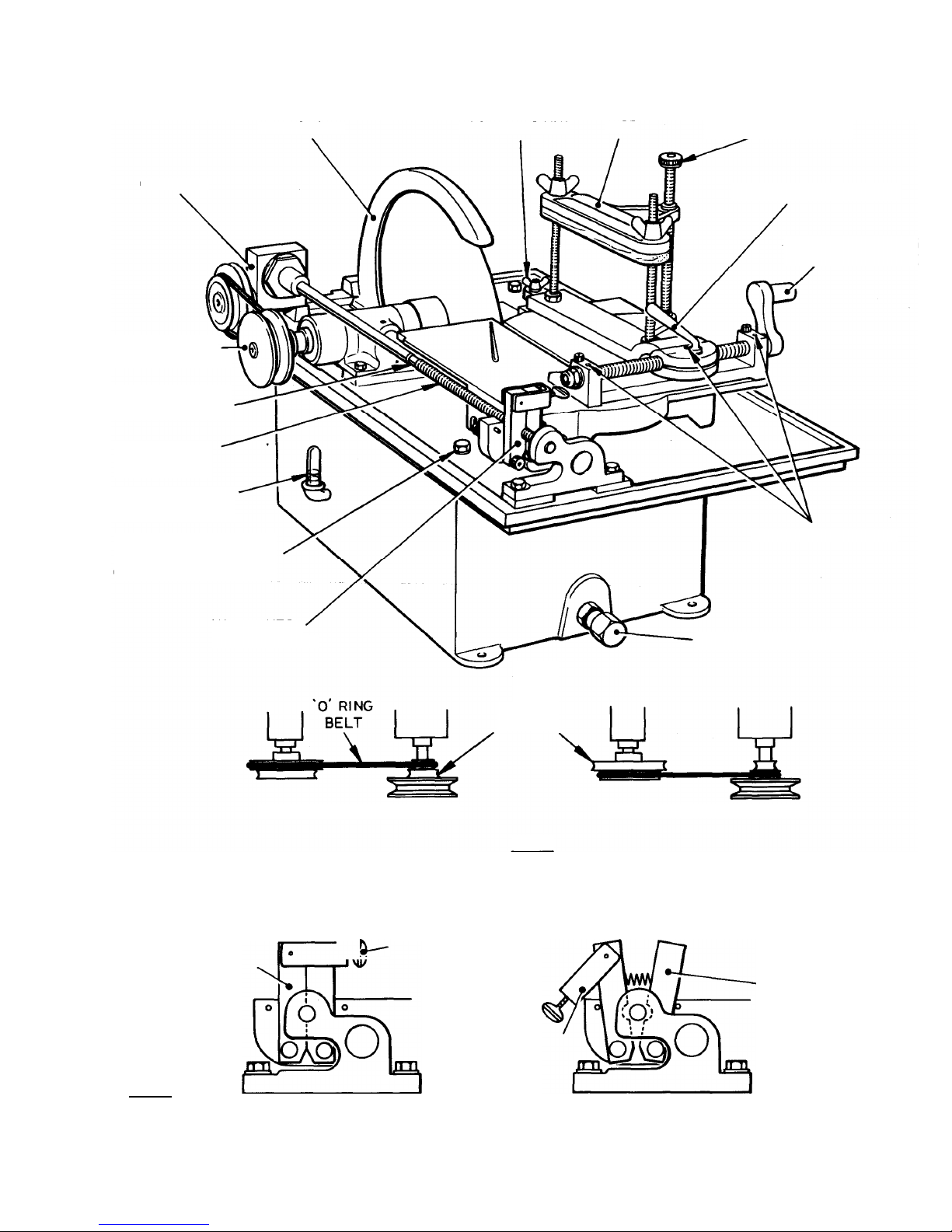
a. Always use coolant at the correct level. (See Fig.4)
b. Use of water is not recommended but allowed in special circumstances.
c. Diamond Saw Lube mixed 5 parts to 95 parts water is recommended for most cutting requirements.
d. Kerosene, Diesoline, transformer oil or light mineral oil can be used in a well ventilated area.
2. USE OF VICE
a. Hold rock in vice, level top jaw with levelling screw then tighten wing nuts.
b. Test rock for movement. If it moves loosen the screws and start again.
c. One complete turn of the slab thickness screw handle gives 1/16" sideways movement.
d. Lock vice to slab thickness screw by tightening front screw lever and back wing nut.
3. SAWING
a. Push slide table forward until the rock is nearly but not quite touching the saw blade.
b. Position the saw guard so that it is slightly above the rock and not in line with the vice.
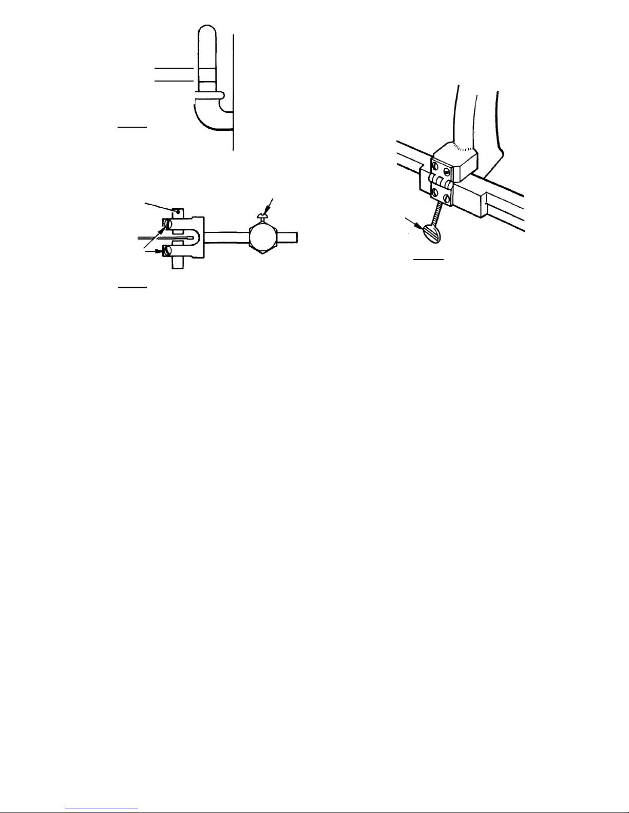
c. Engage the half-nuts on the lead screw. (See Fig. 3)
d. Close the perspex hood. (If fitted)
e. Switch on the power.
f. Leave until slab is cut and the vice held rock has passed the cutting edge of the saw.
g. Switch off power.
4. TO CUT THE NEXT SLAB
a. Release half-nuts.
b. Slide the saw table towards the operator.
c. Firstly loosen the back wing-nut screw.
d. Secondly loosen the front lever.
e. Repeat operation as instructed in part 2b.
5. Keep the saw blade sharp by regularly running a small cut into a silicon carbide dressing stick or a worn grinding wheel.
6. Do not position the vice so that it will be cut by the saw blade.
7. Make sure that the saw guard is free from all forward movement of both the vice and rock by using the raising screw at the rear of the
machine. (See Fig. 6)
8. Keep the saw running centrally by adjusting the Teflon guides to be found beneath the sliding table. (See Fig. 5)
9. Always disconnect feed drive belt when sawing is finished.
10. Remember NEVER USE WATER
11. For TRIMMING SLABS the vice may be removed by taking out the two counter sunk screws that hold it to the sliding table. After having
removed the screws and completely loosened the back screw wing nut,the vice may be slid off to the right.
When trimming, use a gentle forward pressure so as to avoid pushing the blade sideways.
12. To clean out the coolant tank, which becomes necessary when the saw throws up too much sludge, firstly remove the
saw
for safety
against damage, secondly remove the four hexagonal headed bolts; the top section may then be lifted off the tank.
13. Always leave the saw clean by wiping off loose rock particles with a dry rag, and by cleaning the drive screws with a brush before finishing.
14. When replacing the top section remember to re-pack the rear section of the coolant tank in order to avoid "throw-out" of coolant liquid.
15.When placing the machine for use, have it slightly tilted toward the rear so that the coolant thrown up by the saw, will run back through
the drain holes, which should be kept free of dirt.

Table of contents
Popular Saw manuals by other brands

Bosch
Bosch GSG 300 Professional Original instructions

DeWalt
DeWalt DCS361 instruction manual

Scheppach
Scheppach Basa 5.0 Translation from the original instruction manual

Hercules
Hercules HE79 Owner's manual & safety instructions

Silver Storm
Silver Storm 69670 instruction manual

CMi
CMi 466957 operating instructions