manuals.online logo
Brands
  1. Home
  2. •
  3. Brands
  4. •
  5. Gems
  6. •
  7. Accessories
  8. •
  9. Gems LS-800 HLI Training manual

Gems LS-800 HLI Training manual

Environmental Products
Model LS-800 HLI
High Level Indicator
Instruction Bulletin No. 155896
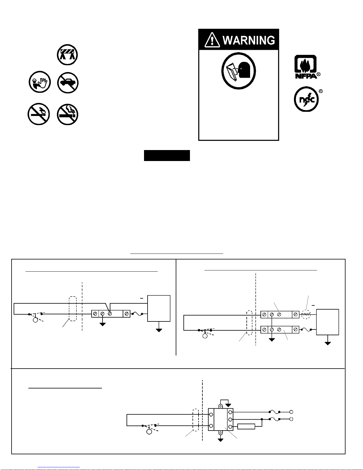
These Sensors may not be compatible with indicating
and alarm equipment supplied by other manufacturers
Note: LS-800 HLI sensors are non-voltage producing devices and do not contain energy storing com-
ponents. However, since primary use is in hazardous locations, an appropriate intrinsically safe inter-
face device is required.
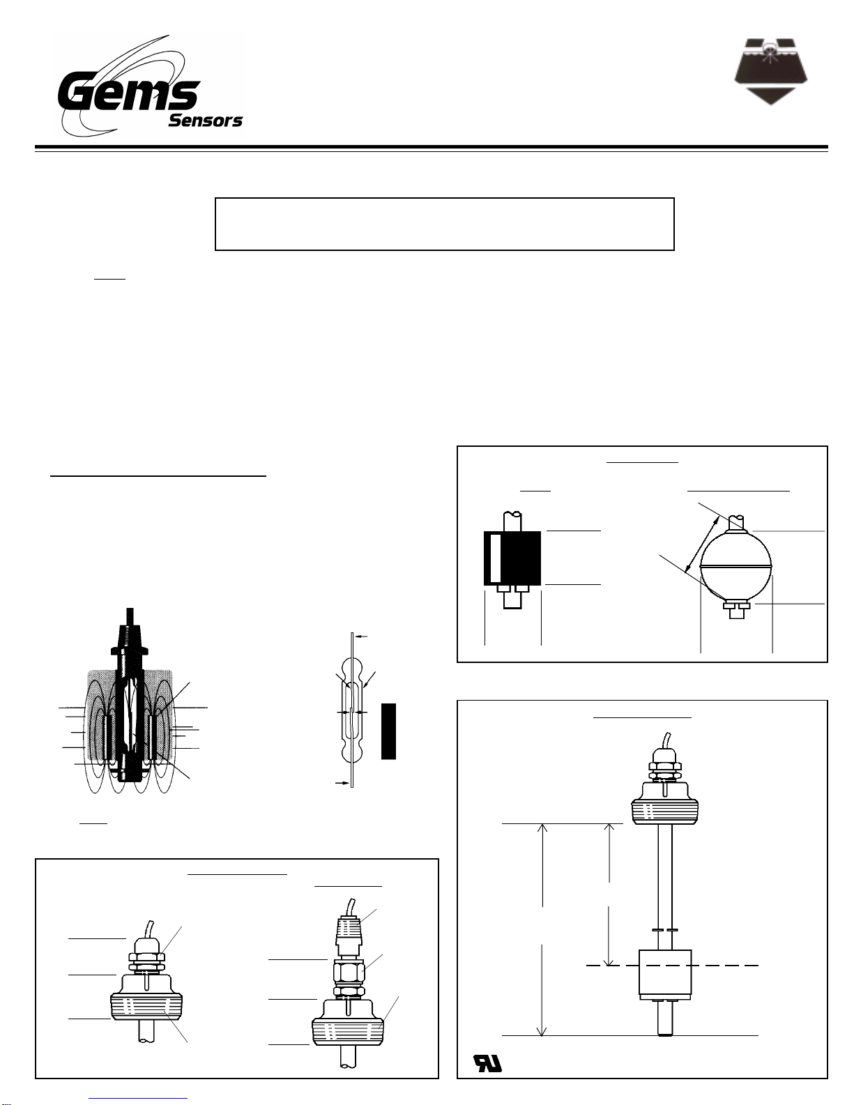
Gems LS-800 HLI liquid level sensor operates on a direct,
simple principle. A float is equipped with powerful, permanent
magnets.Asthefloatrisesorlowerswithliquidlevel,itactuates
amagnetic reed switch mounted within the stem. This condition
either opens or closes the electrical circuit to operate an exter-
nal alarm or control circuit. When mounted vertically, this basic
design provides a consistent accuracy of ±1/8th inch.
Sensor Operating Principle
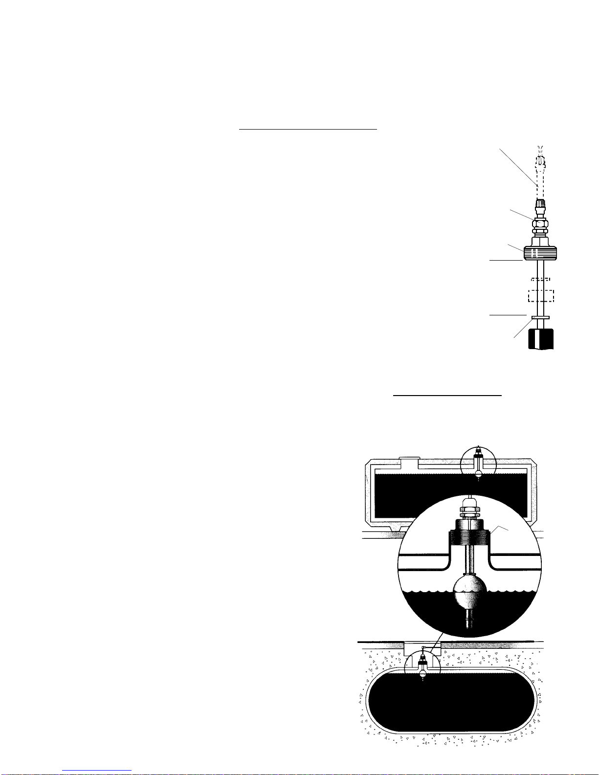
Gems LS-800 HLI High Level Indicator has a 2" NPT mounting, making it ideal for use in underground and aboveground
storage tanks. When mounted vertically at the tank top, it reliably indicates high liquid level. This indicator is exceptionally
versatile. The unit adapts to just about any environment due to rugged construction and the multiple design options avail-
able. The LS-800 HLI is available in brass or stainless steel, making it suitable for use with a wide range of liquids.
Adjustable versions of the LS-800 HLI are available for varying tank sizes. A special cinch nut on the mounting allows the
stem to travel up or down, to fine-tune actuation points. The extent of the adjustment depends on the unit length and dis-
tance from the mounting to the highest float stop.
Note: Please refer to specific Gems outline drawings for
operational specifications.
Permanent
Magnet
Float
Hermetically
Sealed Magnetic
Reed Switch
N
S
Reed
Switch Glass
Envelope
NS
N
S
MAGNET
Adjustable
1-1/4"
Ref.
1-1/2"
Ref.
Liquid Tight
Fitting
2" NPT
1-5/16"
Ref.
1-1/2"
Ref.
1/2" NPT
Adjustment
Nut
2" NPT
Mounting Types
Float Types
Nitrile 316 Stainless Steel
1-13/16"
(46.0 mm)
1-7/8" Dia.
(47.6 mm)
!
!
!
!
2"
(50.8 mm)
2-3/32"
(53.3 mm)
2-9/64"
(54.2 mm)
!
!
!
!
Actuation Level
LO ± 1/16"
(Length
Overall)
L1 ± 1/8"
Actuation
Level
2" Min.
(63.5 mm)
!
!
®
Read all instructions before beginning - Follow all safety precautions
Barricade the area
Do not allow vehicles
or unauthorized people
in the work area
Do not smoke or allow
open flames in the
work area
WARNINGS
Read the instructions and warnings carefully before installing the sensor. This unit must be installed in accor-
dance with National Electrical Code ANSI/NPFA-70, 1990; as well as Federal, State and local codes and any
other applicable safety codes.
1. To avoid electrical shock, which could kill you, be sure AC power to monitor is off during installation.
2. The nature of the sensor is that it is a non-voltage producing device, containing limited energy-storing
components. However, since its primary use is in a hazardous location, an appropriate intrinsically safe
interface device must be used.
Note: Failure to observe these warnings could result in serious injury and
death, as well as undetected potential environmental and health hazards.
Dangerousenvironment.
Failure to install this equipment in
accordance with NFPA 30A and
NFPA 70 could result in severe
injury or death.
Read, understand and follow
NFPA 30A and NFPA 70.
Safe-Pak
®
is an intrinsically
safe, solid-state relay.
If two signal lines must be maintained at above ground potential, an individual zener barrier is required per single line.
Typical Wiring Diagrams
Hazardous
Area Non-Hazard-
ous Area
Black
Red
N.O. Dry
or
N.C. Dry 2-Conductor
Cable
321
Fuse
()
(+)
DC
Power
Supply
Annunc.
Non-Isolated System – Single Zener Barrier
Black
Red
N.O. Dry
or
N.C. Dry 2-Conductor
Cable
321
Fuse
DC
Power
Supply
Annunc.
Non-Hazard-
ous Area
Hazardous
Area
Signal
Return
Barrier
Supply Barrier
Sense
Resistor
Isolated System – Dual Zener Barrier
()
(+)
Single Safe-Pak®Relay
Black
Red
N.O. Dry
or
N.C. Dry 2-Conductor
Cable
Hazardous
Area Non-Hazard-
ous Area
Fuse
Fuse
Load
SAFE-PAK
Hot VAC
Neutral VAC
- IMPORTANT -
This manual assumes all preliminary site preparation is completed and that
field wiring from the monitor to the sensor junction box is in place.
A. Pre-Installation Sensor Testing
1. Temporarily connect the two-wire sensor cable to the
field wires in the sensor junction box.
2. Turn power on.
3. Turn the LS-800 HLI upside down. Audible and visual
indicators should alarm.
4. To remove alarm condition, turn the sensor right side
up.
B. Sensor Installation Instructions
1. Turn off power to the control.
2. Apply thread tape or pipe sealant to male threads on
the 2" NPT of LS-800 HLI.
3. Install LS-800 HLI hand-tight, plus 1-1/2 to 2-1/2
turns.
4. Tighten using wrench: 1 to 1-1/2 turns past hand-
tight.
5. Feed sensor cable through the cord grip on the
junction box.
6. Tighten cord grip nut to ensure a watertight seal at
the cable entry.
7. Using the wire nuts, connect the 2-wire cable to the
field wires in the sensor junction box.
Installation Instructions
For Adjustable Mounting:
A special cinch-nut on this
mounting allows stem to
travel up or down for fine-
tuning the actuation points.
The extent of adjustment
depends on unit length and
distance from mounting to
highest float stop.
To adjust unit, loosen adjust-
ment nut, slide center stem to
desired location and tighten
nut.
Unit Stem
Adjusted Upward
Adjustment
Nut
Mounting
Max.
Adjust.
Float Stop
!
!
Typical Installation
2"
NPT
AST
UST
!"Underground Storage Tanks
!"Aboveground Storage Tanks
P/N 155896
Rev. A
Maintenance
Note: Please consult your state E.P.A. office or appropriate regulatory
agency regarding periodic inspection of the sensor. There are no user
serviceable parts.
WARNING
Product must be maintained and installed in strict accordance with the
National Electrical Code and the applicable GEMS technical bulletin
and instruction bulletin. Failure to observe this warning could result in
serious injuries or damages.
Warranty
Gems’ standard warranty applies

Other Gems Accessories manuals

Gems RotorFlow RFS-2500 Series Training manual

Gems

Gems RotorFlow RFS-2500 Series Training manual

Gems XT-1000 Guide

Gems

Gems XT-1000 Guide

Popular Accessories manuals by other brands

Inficon PGE500 operating manual

Inficon

Inficon PGE500 operating manual

Furzone 40800 manual

Furzone

Furzone 40800 manual

Panasonic MA3Z792 (MA792) Specifications

Panasonic

Panasonic MA3Z792 (MA792) Specifications

Woodstock THE SHOP FOX W1500 instructions

Woodstock

Woodstock THE SHOP FOX W1500 instructions

Bellman & Symfon ER20XS user manual

Bellman & Symfon

Bellman & Symfon ER20XS user manual

Volirium Flytec Balloon Live Sensor user manual

Volirium

Volirium Flytec Balloon Live Sensor user manual

urmet domus 1033/351 Installation booklet

urmet domus

urmet domus 1033/351 Installation booklet

CyberPower CP5000PEG Product guide

CyberPower

CyberPower CP5000PEG Product guide

ekwb EK-FC1080 GTX Ti TF6 installation manual

ekwb

ekwb EK-FC1080 GTX Ti TF6 installation manual

Oregon Scientific THGN800 user manual

Oregon Scientific

Oregon Scientific THGN800 user manual

eXempt C3 Pro user manual

eXempt

eXempt C3 Pro user manual

BFT DCW installation manual

BFT

BFT DCW installation manual

LEGRAND Wattstopper DT-305 manual

LEGRAND

LEGRAND Wattstopper DT-305 manual

Makita DFJ206 instruction manual

Makita

Makita DFJ206 instruction manual

OHAUS DEFENDER SERIES Service manual

OHAUS

OHAUS DEFENDER SERIES Service manual

BEA CGS-KF112 manual

BEA

BEA CGS-KF112 manual

PCB Piezotronics IMI SENSORS M641B61 Installation and operating manual

PCB Piezotronics

PCB Piezotronics IMI SENSORS M641B61 Installation and operating manual

Emos P0072 manual

Emos

Emos P0072 manual

manuals.online logo
manuals.online logoBrands
  • About & Mission
  • Contact us
  • Privacy Policy
  • Terms and Conditions

Copyright 2025 Manuals.Online. All Rights Reserved.