Adjustment :
Warning: Only the -SP, -TS, -FLA and -FLSA models are adjustable.
Warning: All adjustments shall be erformed while a lying a controlled and monitored hydraulic ressure using fittings and hardware of a ro riate
ressure ca ability. The electrical contacts shall also be monitored by a digital multimeter or by using LED indicator lights of suitable electrical rating
to avoid damaging the contacts.
Danger: The adjustment screw is electrically conductive to the contacts. Therefore, to revent an electric shock always use insulated tools and only
monitor the circuit with a digital multimeter or low voltage (<12 VDC) LED lights while adjusting the set oints. Never contact any wire, cable,
connector in or terminal blade with a conductive ortion of the adjusting tool while adjusting the switch.
Tools Required: A 5/32" (4 mm) security style hex key is required to adjust the set oint. The security hole must be 0.102" (2.6 mm) diameter minimum
with a 0.13" (3.3 mm) minimum de th . The use of a standard 5/32" (4 mm) hex key will cause damage to the actuator ti and revent the user from
achieving the high end of the set oint range due to the hex key "camming" out.
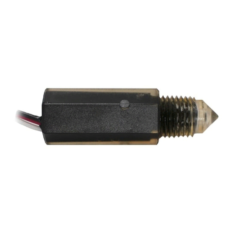
1. Accessing the Adjuster: Remove the black silicone rubber ca . See the enclosed configuration drawing for the location based on the s ecific model. It
is either between the two terminal blades on units with S ade or Terminal Screw terminations or located between the wire exits on units with flying
leads.
2. Adjusting the set oint: Insert the hex key and rotate slightly in either direction until the hex flats engage. Increase the ressure a lied to the switch
while monitoring both the ressure and the continuity of the switch. Note the ressure at which the continuity changes (circuit o en to closed for A
circuits; circuit closed to o en for B circuits). Lower the ressure back to ambient. If the set oint desired is higher than the noted ressure, turn the
hex key clockwise to increase the set oint. Raise the ressure again until the continuity changes. Note the new set oint. Decrease the ressure to
ambient. If the set oint is now lower than desired, rotate the hex key counterclockwise to lower the set oint. Kee raising and lowering the ressure
and rotating the hex key until the desired set oint is obtained. This ty ically takes a few attem ts to achieve the target set oint. Best results are
obtained if small (less than 1 turn) rotational movements of the adjustment screw are made at one time. The adjustment range is engraved on the
hex flats of the switch for reference. Any rising or falling set oints can be obtained within the range listed with ro er adjustment.
Field Locking of the Adjustment Screw (if req'd): The adjustment screw is self-locking from the factory. However, in high vibratory and a lications
where the field adjustment will be re etitive, it may be desirable to increase the factory's self-locking breakaway torque. Gems recommends that 1
dro of Loctite (r) 290 dis ensed from an 0.020" diameter syringe ti be a lied to the adjustment screw and it's electrical housing interface.
Warning: Loctite 290 is a enetrating Loctite. Therefore, it is critical to revent Loctite from being a lied to the center of the adjustment screw where
the actuator slides or any surface of the adjustment screw hex socket. A lication in these areas could render the switch ino erable. The
a lication of more than 1 dro may allow Loctite to enetrate into the interior of the switch which could also cause switch malfunction.
3. Verification of set oint: Verify the new set oint by slowly increasing and decreasing the ressure (or vacuum) while monitoring the electrical contacts.
Re eat the adjustment rocedure if necessary to obtain the desired set oint.
4. Re lace the Adjustment Screw Ca : After adjusting the set oint and locking the screw (if req'd), insert the black silicone rubber ca firmly into the
adjustment screw access hole.
Warning: Failure to re lace the adjustment screw ca may allow ingress of foreign matter which could cause switch malfunction. In addition, the IP
ratings will not a ly to a switch without a ro erly a lied adjustment screw ca .
Danger: Failure to re lace the adjustment screw ca will ex ose the user to the electrically live adjustment screw.
Performance: Notes
1
Re eatability and set oint of units will vary de ending on tem erature, fluid viscosity and cycle rate. Long term inactuation will lead to a higher initial
set oint reading due to the non-linear behavior of the elastomer seals. Fluids with low and stable viscosities over the ex ected tem erature range will
exhibit better erformance.
2
Deadband values are an a roximation at room tem erature with a 100 C fluid. At lower tem eratures and / or higher fluid viscosities the deadband
will be much larger than the value shown. At high fluid tem erature and a ra id cycle rate, the deadband may be lower than the a roximations given.
Please consult the factory if s ecific statistical analysis is required.
TABLE I
PRESSURE RANGE CODES AND PERFORMANCE
Pressure Range
Code Pressure Range Re eatability
1
Average Deadband
2
10 510-1235 sig (35-85 BAR) +/- 30 si (2.1 Bar) +4% of setting 16% of setting
20 800-1960 sig (55-135 BAR) +/- 48 si (3.3 Bar) +4% of setting 13% of setting
30 1835-3115 sig (125-215 BAR) +/- 110 si (7.6 Bar) +6% of setting 24% of setting
40 2970-4350 sig (205-300 BAR) +/- 190 si (13.1 Bar) +6% of setting 20% of setting
