manuals.online logo
Brands
  1. Home
  2. •
  3. Brands
  4. •
  5. Gems
  6. •
  7. Switch
  8. •
  9. Gems ELS-1100 Series Training manual

Gems ELS-1100 Series Training manual

Installation
1. For NPT threaded units:
a. Use Teflon (TFE) thread tape or Permatex #80725 plastic pipe
sealant to seal thread. Caution: Pipe sealant must not come in
contact with prism surface.
b. Thread sensor into tank wall and tighten by hand. Further tighten
an additional one to two threads past hand-tightness. (Avoid
overtightening, as this may damage threads.)
Materials
Housing and Prism
Operating Pressure
Operating Temperature
Current Consumption
Input Voltage
Output
Repeatability
EMI Susceptability
Approvals
Polysulfone or Nylon
0 to 150 psig, Max.
0°F to 176°F (-17.8°C to +80°C)
18 mA, Approximately
See Part Number Chart
TTL/CMOS Compatible, Open Collector
Output may Sink 40 mA up to 30 VDC
±1 mm
Meets Specification (MIL-STD-461B
Part 2 Modified) of 10 V/M for
Frequency Range 30 to 1000 MHz
(Except 609 MHz = 9 V/M
and 679 MHz = 7.5 V/M)
C.E. EN 61326
Units Labeled UL. File E 108913
Specifications
Note: Not for use in freezing liquids
ELS-1100 Series
Electro-Optic Level Switch
Instruction Bulletin No. 138184 (Rev R)
2. For 1/2" and M12 straight threaded units:
a. Thread sensor into tank wall by hand until sensor housing contacts tank wall surface. ( See below for mating o-ring
gland design information.)
b. The sensor shall be torque tightened to 12 to 24 in-lb ( 1.4 to 2.7 N-m). This range is slightly more than “hand-tight” to
insure sealing, and less than that which would cause housing or thread damage.
c. CAUTION: Under no circumstances shall the sensor be tightened more than 1/6 turn beyond that required to seat the
bottom of the sensor housing with the outside wall of the tank.
3. Sensor may be installed in horizontal or vertical position only.
4. Caution: Do not install sensor close to infrared sources or incandescent light. (Note: Any optical sensor may be affected
by reflective surfaces. Consult Gems if prism is to be less than 2 inches from any reflective surface.)
The test depicted below was performed to determine the sensor immunity level to ambient light. The recorded ambient is
the maximum level at which the sensor performs/detects normally.
Note: 1 Ft-Cd = 10.7 Lux
Above testing is based on minimum readings of at
least two (2) samples.
Sensor Type Black Container Opaque Container
ELS-1100 Polysulfone 300 Ft-Cd
ELS-1100 TFE
ELS-1100HT Isoplast
ELS-1200 RE
ELS-1200
ELS-1200CR
ELS-1100 Nylon
45 Ft-Cd
100 Ft-Cd 25 Ft-Cd
500 Ft-Cd 250 Ft-Cd
25 Ft-Cd
250 Ft-Cd
>1000 Ft-Cd
400 Ft-Cd
65 Ft-Cd
700 Ft-Cd
25 Ft-Cd
25 Ft-Cd
Wet
Wet
Wet
Wet
Wet
Wet
Dry
Wet
Dry
Dry
Wet
Wet
Wet
Dry
Dry
Wet
Wet
Dry
Dry
Dry
Wet
5 VDC
10-28 VDC
138167
144225
144235
166541
175631
187575
187590
142700
143570
143575
143577
143580
143585
143590
148973
157750
169555
169556
175632
187580
187585
Probe Condition
At Current Sink
Input
Power Part
Number
Variac
a
Test
Sensors Light Meter
GE Model #214
Test Container(s)
Installation (Contd.)
5. Connect VDC (±10%) power to red lead; return (-) to
black lead. Caution: Do not connect output to VDC
power without a load.
6. Output Configuration: See Wiring Diagrams.
Typical Wiring Diagrams
Black Switch
Red
White
Input
Power
+ VDC
Load
+ VDC
Switch
Red
White
Input Power
+ VDC
Black
*
**L
O
A
D
Switch
Input
Power
+ VDC
Load
+ VDC
Red
White
**
Black
Notes
*TTL/CMOS Output: For levels greater
than 5 volts, a 10K pull-up resistor is
required at the output.
** Maximum Load = 40mA @30 VDC
Maintenance
Sensor may require a periodic cleaning of prism surface.
Chlorinated hydrocarbons must not be used for cleaning.
A mild detergent may be used to clean prism surface.
Return Policy
Returns are accepted on stock items up to 30 days from date of
order. You must contact our Returns Department for a Return
Authorization (RA) number. Return the goods - freight prepaid - in
the original container and include original packing slip.
C. O. D. returns are not accepted. Gems reserves the right to
apply restocking charges.
Tel: 860-793-4357
Fax: 860-793-4563
Gems Sensors Inc.
One Cowles Road
Plainville, CT 06062-1198
Toll-Free: 1-800-378-1600
• Gems products must be maintained and installed in strict accordance with the National Electrical
Code and the applicable Gems Product Instruction Bulletin that covers installation, operation and
proper maintenance. Failure to observe this information may result in serious injury or damages.
•For hazardous area applications involving such things as, but not limited to, ignitable mixtures,
combustible dust and flammable materials, use an appropriate explosion proof enclosure or
intrinsically safe interface device.
•Please adhere to the pressure and temperature limitations shown throughout this catalog for our
levelandflowsensors.Theselimitationsmustnotbeexceeded.Thesepressuresandtemperatures
take into consideration possible system surge pressures, temperatures and their frequencies.
•Selection of materials for compatibility with the media is critical to the life and operation of Gems
products. Take care in the proper selection of materials of construction, testing is required.
•Stainless steel is generally regarded as safe by NSF and FDA.
•NSF-approved sensors are made of materials approved for potable water applications according
to Standard 61.
•Life expectancy of switch contacts varies with application. Contact Gems if life cycle testing is
required.
•Ambient temperature changes do affect switch set points, since the gravity of a liquid can vary with
temperature.
•Oursensorshavebeendesigned to resist shock and vibration. However, shock and vibration should
be minimized.
•Filterliquidmediacontainingparticulateand/ordebristoensuretheproperoperationofourproducts.
•Electrical entries and mounting points in an enclosed tank may require liquid/vaporsealing.
•Our sensors must not be field-repaired.
Important Points:
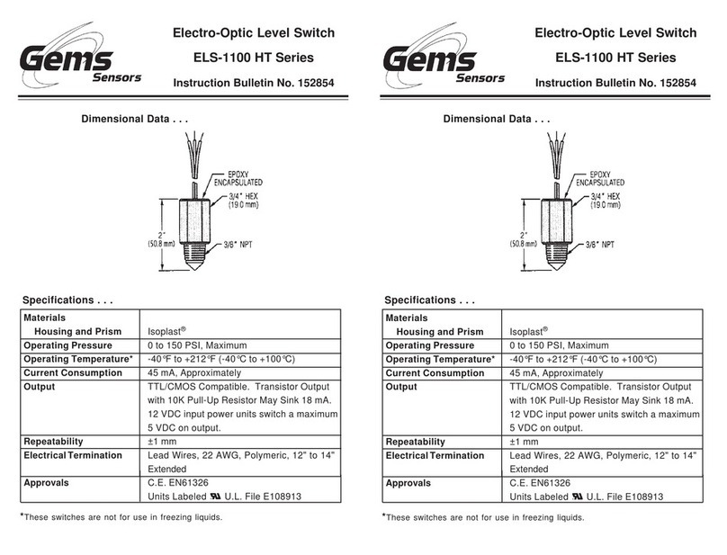
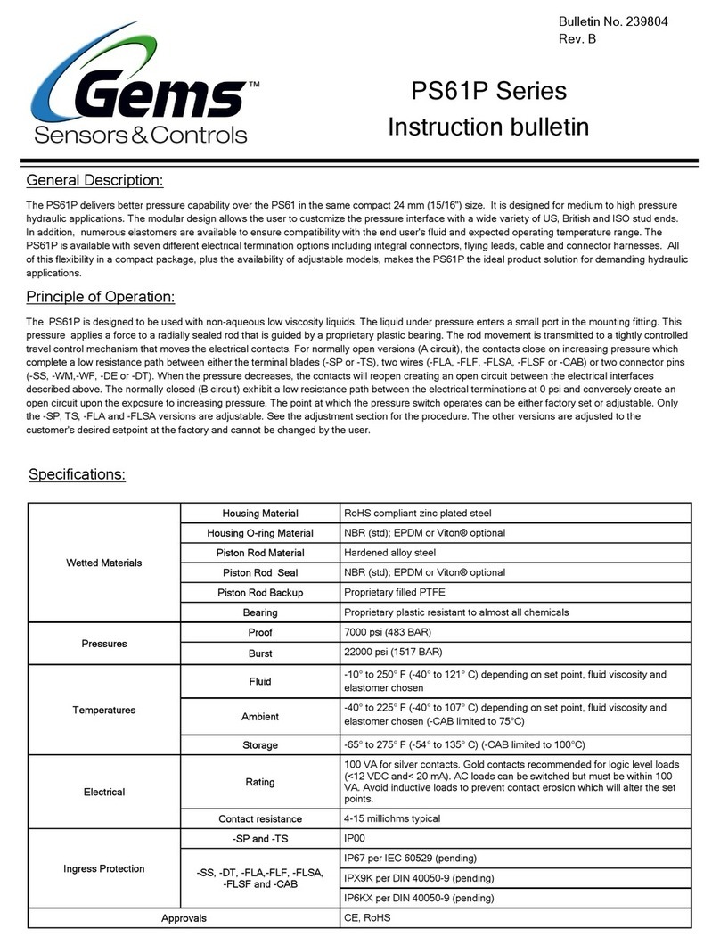
Dimensions
1/4” NPT Mounting 1/4” NPT Mounting
with 3/8” Conduit 1/2” Straight Thread
Mounting with O-Ring
M12x1 Straight Thread
Mounting with O-Ring “Fish” Pull Ring
Flange Mounting
Threaded Holes Not Required
Electrical Termination: Lead Wires, 22 AWG, PVC Jacketed, 12” to 14” Extended
Electrical Termination: Lead Wires, 22 AWG, PVC Jacketed, 12” to 14” Extended 25’ Cable, 22 AWG, PVC Jacketed
Lead
Wires
2-5/32”
(54.7 mm) Epoxy
Encapsulated
5/8” HEX
(15.9 mm)
1/4”
NPT
2-5/32”
(54.7 mm)
5/8” HEX
(15.9 mm)
1/4”
NPT 3/8” NPT
Mounting
2-5/32”
(54.7 mm)
5/8” HEX
(15.9 mm)
Viton
O-Ring
1/2” - 20
UNF .47”
Ref.
.47”
Ref.
2-5/32”
(54.7 mm)
5/8” HEX
(15.9 mm)
Viton
O-Ring
M12 x 1 ←
→2-5/8” Ref.
(66.7 mm)
Removable PVC
Fish Pull Ring 5/8” HEX
(15.9 mm)
Cable
2.16” Ref.
1/4” Max. Wall Thickness
1/8” Thick
Viton Gasket 11/16”-16 Thd. REF
←
→
Mating O-Ring Gland Design
1/2" Straight Thread M12 X 1 Straight Thread
SAE #5 TUBE FITTING 12° .555
.550 .108
.093
1/2-20 UNF 2B
.020
[.50mm]
∅ .570 ± .002
[14.5 ± .05 mm]
M12 X 1 - 8G
45°
.150
[3.80mm]
∅(AT TOP)
This manual suits for next models

22

Other Gems Switch manuals

Gems LS-2050 Series Training manual

Gems

Gems LS-2050 Series Training manual

Gems PS61P Series Training manual

Gems

Gems PS61P Series Training manual

Gems ELS-1100 Series Training manual

Gems

Gems ELS-1100 Series Training manual

Gems ULS-100 Training manual

Gems

Gems ULS-100 Training manual

Gems PS31 Training manual

Gems

Gems PS31 Training manual

Gems FS-600 Series User manual

Gems

Gems FS-600 Series User manual

Gems LS-700 Series Training manual

Gems

Gems LS-700 Series Training manual

Gems ELS-1100 HT Series Training manual

Gems

Gems ELS-1100 HT Series Training manual

Gems SureSite series Installation and operating instructions

Gems

Gems SureSite series Installation and operating instructions

Popular Switch manuals by other brands

Planet LRP-822CS user manual

Planet

Planet LRP-822CS user manual

FOR-A MFR-4100 Quick setup guide

FOR-A

FOR-A MFR-4100 Quick setup guide

Tripp Lite B007-008 Specifications

Tripp Lite

Tripp Lite B007-008 Specifications

Ntron 105FX-POE User manual & installation guide

Ntron

Ntron 105FX-POE User manual & installation guide

Avtech WiSH Installation note

Avtech

Avtech WiSH Installation note

Tripp Lite B022-002-KT-R user manual

Tripp Lite

Tripp Lite B022-002-KT-R user manual

SMART-AVI DVN-16Pro quick start guide

SMART-AVI

SMART-AVI DVN-16Pro quick start guide

Timeguard NTTHDA Installation and operating instructions

Timeguard

Timeguard NTTHDA Installation and operating instructions

HIK VISION DS-3E2300P Series user manual

HIK VISION

HIK VISION DS-3E2300P Series user manual

SMART-AVI D2H-4P Quad quick start guide

SMART-AVI

SMART-AVI D2H-4P Quad quick start guide

AirLive IGR-842PoE user manual

AirLive

AirLive IGR-842PoE user manual

Black Box KV6222A-R2 user manual

Black Box

Black Box KV6222A-R2 user manual

HIK VISION DS-3D2216P Hardware installation manual

HIK VISION

HIK VISION DS-3D2216P Hardware installation manual

Planet WGSW-24040 user manual

Planet

Planet WGSW-24040 user manual

3One data ICS5530-16GS8GC6XS-2P220 Quick installation guide

3One data

3One data ICS5530-16GS8GC6XS-2P220 Quick installation guide

Planet GS-5220-8P2T2S Quick installation guide

Planet

Planet GS-5220-8P2T2S Quick installation guide

Timeguard ZV210 operating instructions

Timeguard

Timeguard ZV210 operating instructions

Black Box KV7012A instruction manual

Black Box

Black Box KV7012A instruction manual

manuals.online logo
manuals.online logoBrands
  • About & Mission
  • Contact us
  • Privacy Policy
  • Terms and Conditions

Copyright 2025 Manuals.Online. All Rights Reserved.