GENASYS 360 User manual

GENASYS 360
GENASYS INC.
GENASYS 360
INSTALLATION MANUAL
16262 West Bernardo Drive
San Diego, CA 92127
www.genasys.com
Manual Part No.: 119509-00 Rev. A
Revised: December 2020
CAGE: 1K3W7
Copyright, 2020, Genasys Inc.
FAULT
AMPLIFIER ON
POWER


GENASYS 360
GENASYS INC.
Manual Part NO.: 119509-00 Rev. A
i
Contents
1.0 Safety Information ................................................................................................................... 1
2.0 Overview .................................................................................................................................. 2
3.0 System Details.......................................................................................................................... 3
3.1 Stacks ................................................................................................................................... 3
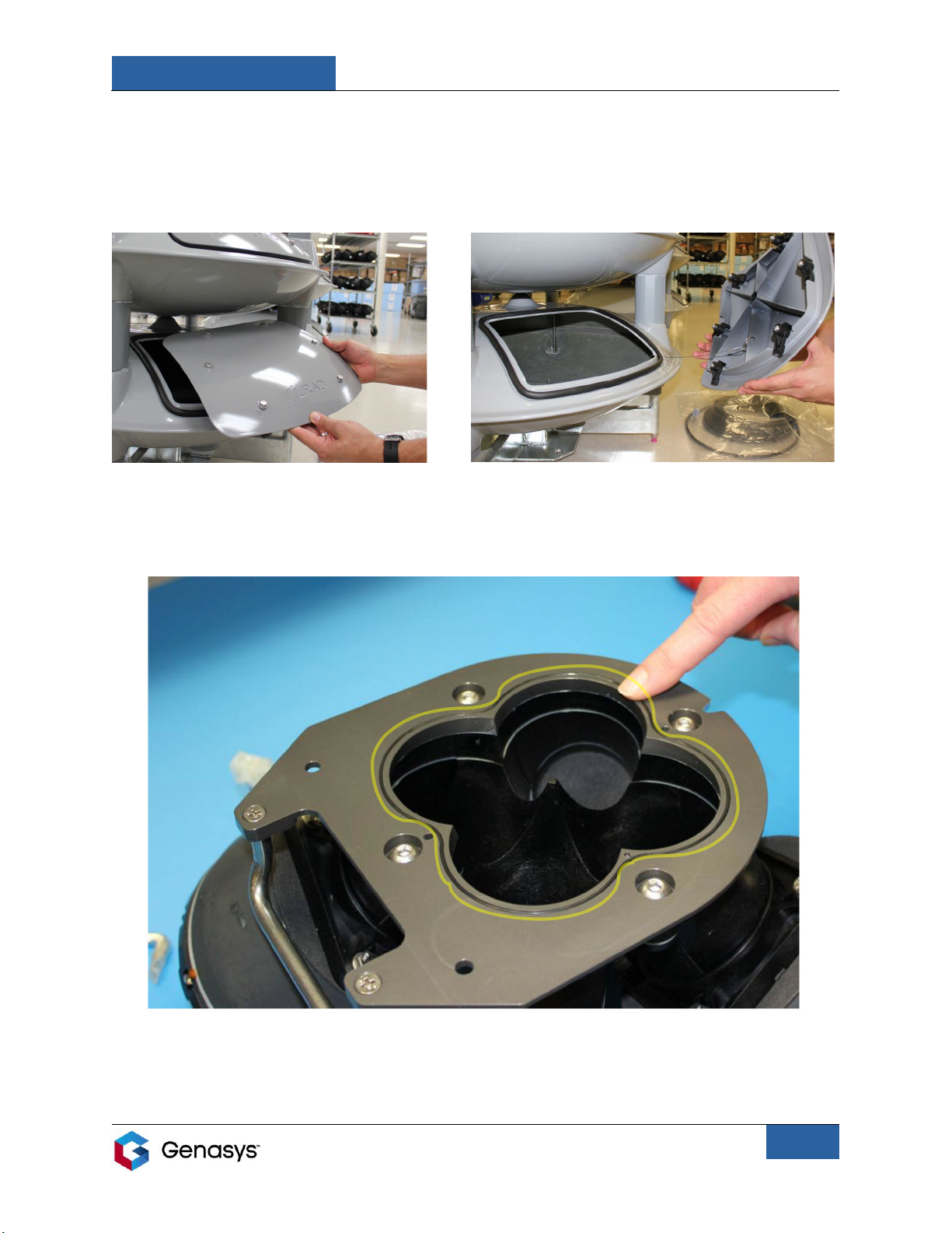
3.2 Acoustic Driver Assembly..................................................................................................... 4
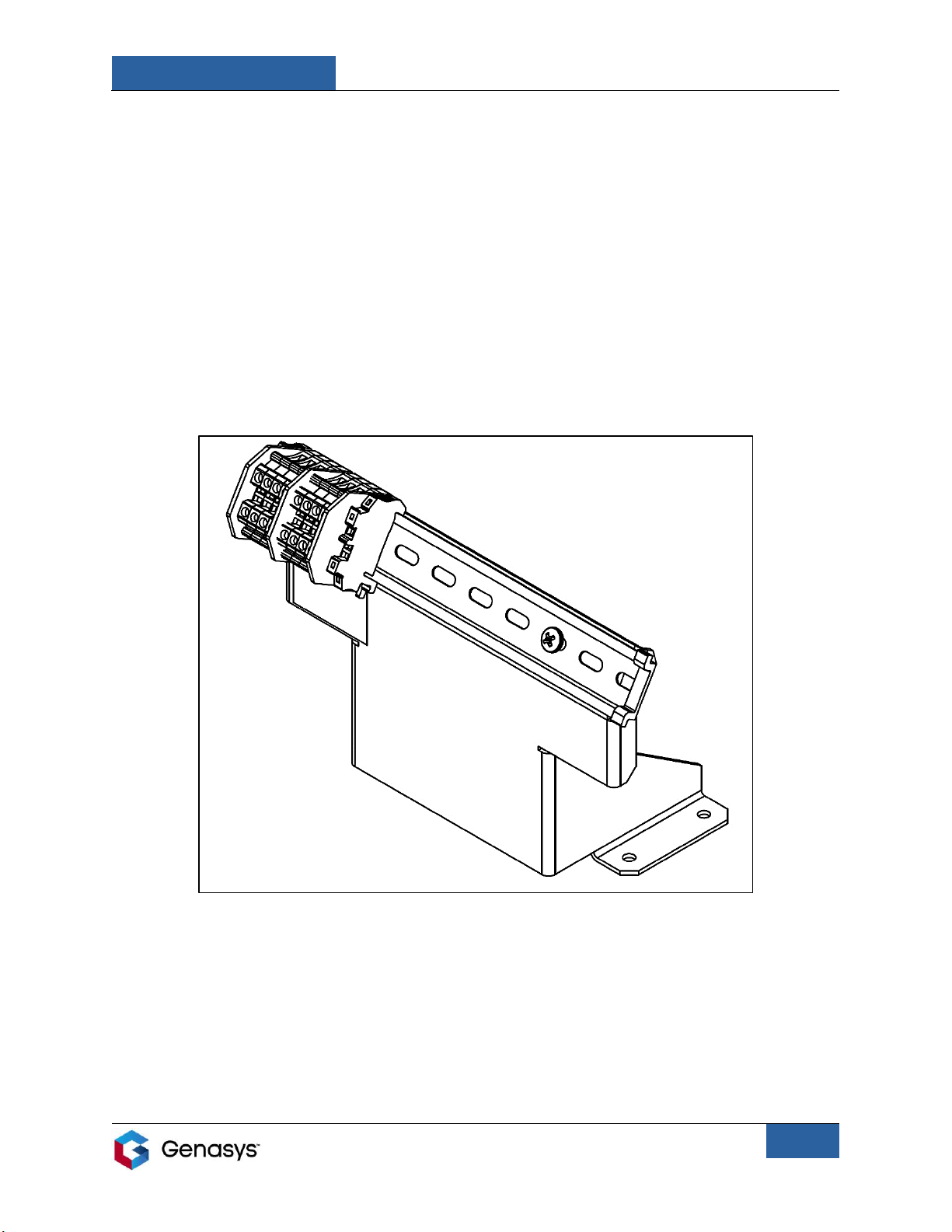
3.3 Terminal Blocks ..................................................................................................................... 5
4.0 Installing the Acoustic Driver Assembly................................................................................... 6
5.0 Mounting the 360 ................................................................................................................... 10
6.0 Connecting: Audio.................................................................................................................. 13
6.1 3RU Amplifier Unit ............................................................................................................. 16
6.2 Control Cabinets ................................................................................................................. 18
7.0 Connecting: Software............................................................................................................. 20
7.1 Genasys Emergency Management (GEM) Software.......................................................... 20
7.2 Streamer Software ............................................................................................................. 20
8.0 Specifications ......................................................................................................................... 21
8.1 360X Specs ......................................................................................................................... 21
8.2 360XL Specs........................................................................................................................ 22
9.0 Technical Support .................................................................................................................. 23

GENASYS 360
GENASYS INC.
Manual Part NO.: 119509-00 Rev. A
1
1.0 Safety Information
Note the following safety instructions when assembling, installing, and operating the Genasys
360.
•Read and adhere to the instructions detailed in this manual. Keep this manual with the 360
at all times.
•Make sure all steps are properly taken during assembly and installation. Failure to follow
these steps may result in damage to the device and/or void the warranty.
•Personnel operating the device should always use hearing protection and limit exposure to
high volume audio output.
•Do not bend, twist, or pinch cables, especially at connection points.
•Make sure all cable connection ports are kept clean and clear of debris.
•Only use attachments/accessories specified by Genasys.
•Refer all servicing and maintenance to qualified personnel.

GENASYS 360
GENASYS INC.
Manual Part NO.: 119509-00 Rev. A
2
2.0 Overview
This manual will provide instructions for installing the Genasys 360 mass notification
speaker system.
There are two 360 models available: 360X and 360XL.
The 360X is a lighter and smaller speaker system, while the 360XL offers a larger
broadcasting radius and higher sound pressure level (SPL).
The Genasys 360 is an outdoor loudspeaker that uniformly projects highly intelligible voice
messages and alert sounds with 360° coverage. Audio is broadcast from the 360 via one or
more acoustic driver assemblies.
The 360 is designed to be mounted atop a standalone pole or on a non-penetrating roof
mount.
•Poles and roof mounts are not standard accessories and must be purchased
separately.
360 speaker systems are available in one, two, four and eight emitter configurations.
Broadcasting radius and SPL will increase in proportion to the number of emitters.
Acoustic Driver Assembly
Genasys 360

GENASYS 360
GENASYS INC.
Manual Part NO.: 119509-00 Rev. A
3
Figure 1
3.0 System Details
3.1 Stacks
Every Genasys 360 system is made up of an array of stacks. The number of stacks will vary
depending on the 360 model and configuration.
Stacks are identified by number, as seen in Figure 1 below. Numbering starts at 0 for the lowest
stack and continues for each stack above.
ST0 is the base stack and contains the terminal blocks that connect the acoustic drivers to the
audio source.
ST1 and above are the emitter stacks, or emitters. Each emitter contains an acoustic driver
assembly, the device’s sound-producing element.
Genasys 360s are named based on the number of emitters in the system.
•For example, Figure 1 is a Four Emitter because it has four emitter stacks.

GENASYS 360
GENASYS INC.
Manual Part NO.: 119509-00 Rev. A
4
3.2 Acoustic Driver Assembly
Each emitter in a 360 speaker system contains a proprietary acoustic driver assembly. The
assembly is made up of four connected drivers. These drivers broadcast the audio from the 360.
Each acoustic driver in the assembly is driven by a maximum of 23 VRMS at frequencies
between 350 Hz and 8.0 kHz. A band-pass filter of 12 dB per octave or better is applied below
350 Hz and above 8.0 kHz.
Acoustic drivers are identified by number, as seen in Figure 2. When inserting the acoustic
driver assembly into the emitter, the back-left driver is DR1 and the numbering continues
clockwise.
Also note the assembly’s handle in Figure 2. Use this handle to hold and insert the assembly
into the emitter.
Section 4.0 provides more information on installing the acoustic driver assembly.
Figure 2
HANDLE

GENASYS 360
GENASYS INC.
Manual Part NO.: 119509-00 Rev. A
5
3.3 Terminal Blocks
ST0 (the base stack) contains the terminal blocks used to connect the acoustic drivers to the
audio source. These terminal blocks are installed on a DIN rail that is mounted inside ST0
(Figure 3).
Internal connection cables run down from the acoustic drivers in the upper stacks and connect
to the tops of the terminal blocks. Cables from the audio source connect to the bottoms of the
terminal blocks.
Section 6.0 provides more information on connecting the 360 to its audio source via these
terminal blocks.
Figure 3

GENASYS 360
GENASYS INC.
Manual Part NO.: 119509-00 Rev. A
6
4.0 Installing the Acoustic Driver Assembly
To begin, users must install and connect their 360’s acoustic driver assembly.
NOTE: Users will need to repeat the steps in this section for each acoustic driver assembly
included in their 360 system.
The number of assemblies will depend on the 360 model and stack configuration.
Perform the following steps to install the acoustic driver assembly inside of its corresponding
emitter stack.
1. Open the access panel on the desired emitter.
•Use a7/16-inch wrench to loosen the six bolts on the access panels (Figure 4).
oThe bolts do not need to be removed completely.
•Press lightly on the center of the panel to compress the sealing gasket and then
turn the bolts by hand to loosen the internal clamps (Figure 5).
LOOSEN SIX
BOLTS
TURN BY HAND
Figure 4
Figure 5
PRESS
LIGHTLY

GENASYS 360
GENASYS INC.
Manual Part NO.: 119509-00 Rev. A
7
2. Remove the panel from the emitter (Figure 6).
•Note that the panel is secured to the emitter with a lanyard. This is to
avoid dropping the panel while performing maintenance in the field
(Figure 7).
3. Apply the provided silicone lubricant evenly along the acoustic driver assembly’s O-ring,
found on the bottom of the assembly. This ring is indicated by the yellow outline in Figure 8.
Figure 7
Figure 6
Figure 8

GENASYS 360
GENASYS INC.
Manual Part NO.: 119509-00 Rev. A
8
4. Insert the assembly into the emitter by lowering the assembly into the opening (Figure 9).
•Rest the bottom of the assembly on the slider plate retainer found inside the emitter
and start to slide the manifold towards the back of the emitter (Figure 10).
5. Prior to sliding the assembly completely into the emitter, connect the cables from DR1 and
DR2 (the two drivers at the rear of the assembly) to the emitter connection cables (Figure
11).
•Align the mating faces of the connectors and firmly push them together until you
hear a click. Press the locking latches on the sides of the connectors to confirm that
they are fully engaged with the locking tabs.
•These driver cables can connect to any of the emitter connection cables.
Figure 10
Figure 9
Figure 11

GENASYS 360
GENASYS INC.
Manual Part NO.: 119509-00 Rev. A
9
Figure 12
6. Slide the assembly completely into the slider plate retainer so the mounting holes align.
7. Hand-tighten the two provided thumbscrews to lock the assembly into position (Figure
12).
8. Connect the cables from DR3 and DR4 (the two front drivers) to the remaining emitter
connection cables (Figure 13).
9. Replace the access panel on the emitter and fully tighten the panel’s bolts.
•Turn the bolts by hand to secure the internal clamps and then tighten the panel’s
bolts using a 7/16-inch wrench.
Figure 13
ASSEMBLY
COMPLETELY ALIGNED
WITH SLIDER PLATE

GENASYS 360
GENASYS INC.
Manual Part NO.: 119509-00 Rev. A
10
5.0 Mounting the 360
Once all acoustic driver assemblies are installed, the Genasys 360 is ready for mounting.
NOTE: Users can mount their 360 immediately after driver assembly installation, or can connect
the 360 to its audio source before mounting. This will depend on the installation
location and the user’s preference.
If the user prefers to first connect to the audio source before mounting, skip to Section
6.0. After completing Section 6.0, return to Section 5.0 and follow the mounting
instructions.
The 360 is designed to be mounted atop a standalone pole or on a non-penetrating roof mount.
This speaker system has been tested to withstand wind speeds of up to 200 mph.
Consult Section 8.0 to determine your 360’s Effective Projected Area, weight, and dimensions.
This information will determine the pole or roof mount design required for mounting.
Ensure mounting device meets all regulations and requirements set by the installation site’s
governing body.
Attach the 360 to the pole top or the roof mount using the hardware and torque specified in
Section 8.0.

GENASYS 360
GENASYS INC.
Manual Part NO.: 119509-00 Rev. A
11
To mount the 360, perform the following steps.
1. Select location for mounting the 360 unit.
•Unit should be mounted in a location that maximizes the number of targets within
the broadcast coverage radius.
2. Install the desired mount. This will either be a pole or a roof mount.
•These mounts are not standard accessories and must be purchased separately.
3. Install lifting straps on the 360 according to Figure 14, below.
•Straps wrap around the top stack and are secured in place by the support rods.
4. Raise the 360 to the appropriate height to be mounted.
•This may require a crane, cherry picker, etc.
Figure 14

GENASYS 360
GENASYS INC.
Manual Part NO.: 119509-00 Rev. A
12
5. Mount and secure the 360 on either the pole (Figure 15) or the roof top mount (Figure 16).
Figure 16
Figure 15

GENASYS 360
GENASYS INC.
Manual Part NO.: 119509-00 Rev. A
13
6.0 Connecting: Audio
The 360 must be connected to an audio source in order to broadcast messages and alerts.
A threaded conduit inlet is provided for running the 70-foot audio cable from the 360 to the
audio source.
The 360 is designed to connect to the following Genasys audio sources:
•3RU Amplifier Unit
•Control Cabinet (Advanced or Compact)
The audio source can be installed on the same mount as the 360 or at a separate location
(Figure 17).
•Consider the length of the 70-foot audio cable when selecting the source’s location.
Figure 17
KEY
1: Genasys 360
2: Audio source
3: Solar Panel*
4: Satellite Terminal*
5: Lightning Rod*
*These are optional accessories that users may
wish to install in conjunction with their 360
model. Contact your Sales Representative for
more information.

GENASYS 360
GENASYS INC.
Manual Part NO.: 119509-00 Rev. A
14
To connect the 360 to its audio source, perform the following steps.
NOTE: For optimal performance, audio wires should be terminated with insulated ferrules.
1. Feed one end of the Genasys 70-foot audio cable through the 360’s threaded conduit inlet,
located on the bottom of the base stack (ST0) (Figure 18).
Figure 18

GENASYS 360
GENASYS INC.
Manual Part NO.: 119509-00 Rev. A
15
2. Connect the 70-foot audio cable’s wire ferrules to the bottom of terminal blocks (Figure 19).
•Going from left to right, insert positive and negative speaker wire pairs in sequence.
•Use a 3-millimeter flathead screwdriver to securely clamp the connected wires.
•Ensure that all speakers are connected in phase.
•Terminal blocks and connections will vary depending on the 360 model and stack
configuration.
3. Run other end of the 70-foot audio cable from the 360 to the audio source.
4. Connect the 70-foot audio cable to the audio source’s speaker outputs.
Sections 6.1 and 6.2 provide information on the audio sources available from Genasys.
The audio source will be determined by your specific 360 model and stack configuration.
Figure 19
NOTE: User’s cables may be different from those shown in the above figure.

GENASYS 360
GENASYS INC.
Manual Part NO.: 119509-00 Rev. A
16
6.1 3RU Amplifier Unit
The 3RU is Genasys’ rack-mounted amplifier unit (Figure 20).
The 3RU is compact, rugged, and designed to fit standard Electronic Industries Alliance (EIA)
amplifier rack-mounting systems.
This amplifier is available in AC or DC versions, and in the following configurations:
•16 x 80 W
•8 x 160 W
3RU units can be daisy chained together to adapt to any 360 model and stack configuration.
The number of 3RU amplifiers used will be determined by the 360.
Figure 20

GENASYS 360
GENASYS INC.
Manual Part NO.: 119509-00 Rev. A
17
To connect the 360 to the 3RU, simply connect the 360’s audio cable to the 3RU’s
corresponding speaker output connectors.
Figure 21 shows how a One Emitter 360X can connect to a 3RU.
3RU Amplifier Unit: Back Panel
To learn more about the 3RU, contact your Sales Representative or consult the 3RU user
manual.
Figure 21
The orange lines represent the
audio cable and its input wires,
which will run from the 360 to the
3RU Speaker Outputs.
This manual suits for next models
2
Table of contents
Other GENASYS Speakers manuals