GENASYS LRAD 1950XL Technical Document

LRAD 1950XL
EQUIPMENT MANUAL
Genasys Inc.
16262 West Bernardo Drive
San Diego, CA 92127
www.genasys.com
Catalog: LRAD-1950XL-MAN
Manual Part No.: 114931-00 rev. B
Revised 13 Jul. 2020
Copyright, 2020, Genasys Inc.

LRAD 1950XL GENASYS INC.
ii
Contents
Contents .....................................................................................................................................ii
1.0 Safety Precautions................................................................................................................4
2.0 Introduction .........................................................................................................................6
3.0 Preparation for Use and Installation .....................................................................................6
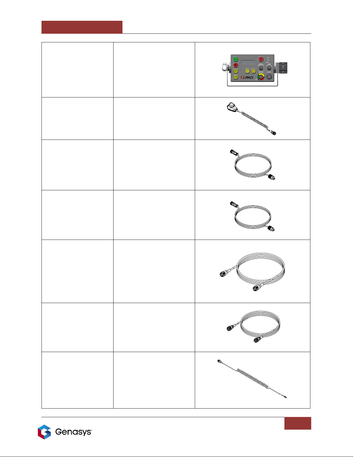
3.1 Parts List...........................................................................................................................6
3.2 Quick Setup Guide...........................................................................................................10
4.0 Principles of Operation.......................................................................................................11
5.0 Operating Instructions........................................................................................................11
5.1 Positioning the LRAD for Operation ................................................................................12
5.2 Aiming ............................................................................................................................13
5.3 Environmental Conditions Affecting Aiming....................................................................13
5.4 System Interfaces ...........................................................................................................14
5.4.1 Main AC Power Switch.............................................................................................14
5.4.2 Electronics Panel Indicator LEDS ..............................................................................14
5.4.3 AC Input Connector..................................................................................................15
5.4.4 Resettable Breaker...................................................................................................15
5.4.5 MP3 Control Unit Indicator LEDs..............................................................................15
5.4.6 Voice Boost Switch...................................................................................................16
5.4.7 Microphone Clip ......................................................................................................16
5.4.8 Sound Projection Switch ..........................................................................................16
5.4.9 MIC/USB Input.........................................................................................................16
5.4.10 Power/Volume Control ..........................................................................................17
5.4.11 Control Unit Connector..........................................................................................17
5.4.12 Power On Hours Meter ..........................................................................................17
5.4.13 MP3 Player Control Buttons....................................................................................17
5.5 Using the MP3 Player......................................................................................................18
5.6 Button Functions ............................................................................................................19
5.7 MP3 Control Unit LCD Display..........................................................................................20
5.8 Downloading Files...........................................................................................................21
5.9 Changing the Alert Tone .................................................................................................22
5.10 Audio File Playback.......................................................................................................22
5.11 Using the Alert Tone .....................................................................................................22
5.12 Other MP3 Player Features...........................................................................................22
6.0 The Recording Microphone ................................................................................................22
7.0 Maintenance, Troubleshooting and Servicing .....................................................................24
7.1 Preventive Maintenance.................................................................................................24
7.2 Fresh Water Rinse...........................................................................................................25
7.3 Cleaning the Head Unit Grill............................................................................................25
7.4 Troubleshooting .............................................................................................................25
8.0 Preparation for Shipment ...................................................................................................27
9.0 Storage...............................................................................................................................27

LRAD 1950XL GENASYS INC.
iii
10.0 Specifications ...................................................................................................................28
11.0 Technical Support.............................................................................................................29

LRAD 1950XL GENASYS INC.
Manual Part No.:114931-00 rev. B
4
1.0 Safety Precautions
The LRAD 1950XL is capable of producing sound pressure levels that have the potential to cause
temporary or permanent hearing damage if not used properly. Always follow the safety
precautions described in this manual as well as on the unit’s operator interfaces.
The following conventions apply in this manual. Please note the warnings and take adequate
measures to ensure safe operation of the unit.
WARNING –Risk of injury or death.
CAUTION –Risk of equipment damage.
Before operating the LRAD 1950XL, do the following:
1. Read these instructions.
2. Keep these instructions in a place known to and accessible by the potential operators of the
LRAD 1950XL.
3. Heed all warnings contained in this document.
4. Follow all instructions detailed in this document.
5. Install in accordance with the instructions contained in this document.
6. Do not install near any heat sources such as radiators, heat registers, stoves, or other
apparatus that produce heat.
7. Do not connect or disconnect any cables to the unit while the primary circuit is live unless
the area is known to be non-hazardous.
8. Do not defeat the safety purpose of the polarized or grounding-type plug. A polarized plug
has two blades with one wider than the other. A grounding type plug has two blades and a
third grounding prong.
9. The wide blade or the third prong of the power cord is provided for your safety. If the
provided plug does not fit into your outlet, consult an electrician for replacement of the
obsolete outlet.
10. Protect the power cord from being treaded upon, excessively bent, creased, or pinched
particularly at the point where the cable assemblies connect to the apparatus.
11. Only use attachments/accessories specified by the
manufacturer.
12. Unplug this apparatus during lightning storms or when
unused for long periods of time.
13. Refer all servicing to qualified service personnel. Servicing is
required when the LRAD 1950XL has been noticeably or
substantially damaged in any way, including cord or plug
damage, seriously dented or breached housings, or if liquid
has penetrated the interior of the device, or any
accessories.
14. The LRAD 1950XL power cord shall be connected to a main
socket outlet with a protective ground connection.
15. Follow the Operation Zones graphic on the back of the LRAD
for guidance on exposure to high acoustic levels.
Figure 1: LRAD 1950XL Safe Zones
100m
800m
15m
10m

LRAD 1950XL GENASYS INC.
Manual Part No.:114931-00 rev. B
5
The following information refers to Figure 1:
a. SPL can exceed 115dB within the indicated red areas at full power. Do not enter
these areas during operation.
b. SPL can exceed 100dB within the indicated yellow areas at full power. These
areas are safe for up to 15 minutes with hearing protection.
c. SPL is below 100dB in the green zone. This area is safe to enter without hearing
protection for up to 15 minutes.

LRAD 1950XL GENASYS INC.
Manual Part No.:114931-00 rev. B
6
2.0 Introduction
The LRAD 1950XL Long Range Acoustic Device is a powerful acoustic hailer that can be used to
project loud, clearly intelligible messages to targets at distances up to 5 Kilometers (3.1 miles).
The acoustic output from the LRAD projects from the Acoustic Array in a focused 30 degree
“cone” of sound. Sound levels outside of this cone are greatly reduced as a result of the
focused nature of the LRAD’s sound projection.
The LRAD includes a ruggedized MP3 player unit that can be used to store digital audio of any
type, as well as a handheld microphone for reproducing live spoken messages. The LRAD’s MP3
player features a built in “Alert Tone” button that instantly broadcasts a loud, piercing alert
sound that can be used to gain the target’s attention.
The LRAD 1950XL has the ability to produce a maximum continuous sound pressure level (SPL)
of 155dB at one meter from the front of the device. With this high output, clear audible
messages can be broadcast to targets at ranges of 1600 to 5000 meters, depending on weather
conditions. This high acoustic output is achieved with a peak power consumption of 1120
Watts.
The LRAD operates using AC input power from a 90 to 260 VAC power source at 50 or 60Hz.
The LRAD must be plugged into a grounded electrical outlet.
The LRAD is constructed of materials that are designed to survive in a marine environment with
proper care and maintenance. A carbon-fiber speaker housing is fitted with 316 stainless steel
hardware and other parts that are either powdercoated or hard anodized. The remote portable
amplifier pack and remote MP3 control unit are environmentally sealed and can be used in all
weather conditions. For further information on environmental specifications for this product,
see the Specifications section of this manual.
3.0 Preparation for Use and Installation
3.1 Parts List
The LRAD 1950XL system components ship in reusable crates. The provided crates should be
stored and used whenever shipping or transporting the LRAD. The following table lists the
various parts that are included with the purchase of the LRAD 1950XL.

LRAD 1950XL GENASYS INC.
Manual Part No.:114931-00 rev. B
7
Table 1: LRAD-1950XL Parts List
Part Number
Description
Image
112376-02
ASSEMBLY, HEAD UNIT, LRAD
1950XL, GROUNDED, GRAY
114379-02
ASSEMBLY, YOKE, 1000X,
1950XL, LOCKING TILT,
1-1/8’ STUD, GRAY
112381-00
ASSEMBLY, AMP PACK, LRAD-
1950XL, DUAL DIA WIRING
107266-00
CABLE ASSEMBLY, USB 2.0,
DOWNLOAD, MP3,
D38999, 48 IN

LRAD 1950XL GENASYS INC.
Manual Part No.:114931-00 rev. B
8
107906-12
CONTROL UNIT, REMOTE
ELECTRONICS, UNIVERSAL,
GRAY, SS
115394-00
MICROPHONE, RECORDING,
NOISE CANCELLING ELEMENT,
METAL BUTTONS, SS
101562-02
ASSEMBLY, POWER CABLE,
GROUND-FIRST, STRAIGHT
PLUG, 50 FT
101562-01
ASSEMBLY, POWER CABLE,
GROUND-FIRST, STRAIGHT
PLUG, 12 FT
109403-35
CABLE, AMPLIFIER PACK TO
HEAD UNIT, 35FT, LRAD-2000X
107920-00
CABLE ASSEMBLY, REMOTE
CONTROL, 20 FT, SS
106584-00
CABLE ASSEMBLY, CD PLAYER,
D38999 TO 3.5MM PHONE, SS

LRAD 1950XL GENASYS INC.
Manual Part No.:114931-00 rev. B
9
114931-00
MANUAL, LRAD 1950XL,
PRINTED, LAMINATED
108089-00
KIT, DUAL TILT LOCK KNOBS,
LRAD-1000Xi
104873-00
HANDLE, LRAD-1OOOX,
REMOVABLE (QTY. 2)
100770-00
EARPLUG, FOAM, W/O CORD,
NRR 33 DB, (QTY. 10)
100778-00
EARPLUG, BANDED, NRR 25 DB,
(QTY. 2)
107767-02
COVER, SOFT, LRAD-1000X,
GRAY

LRAD 1950XL GENASYS INC.
Manual Part No.:114931-00 rev. B
10
104758-00
PACKAGING, CRATE, LRAD-
1000X
3.2 Quick Setup Guide
The LRAD 1950XL can be quickly set up for use by following these basic steps. Reference the
pictorial parts list in the previous section to identify the parts mentioned below.
AC
outlet
1. Install the mounting yoke in an appropriate mounting system. LRAD offers various
mounting options.
2. Place the rubber washers from the tilt lock knob kit over the tilt axis studs so they are
flush with the tilt axis flanges.
3. Lower the head unit onto the yoke, inserting the studs into the vertical slots in the yoke.
4. Screw the tilt lock knobs onto the tilt axis studs and tighten.
5. Install the removable handles on the back of the head unit.
6. Open the lid of the amp pack.
7. Connect either the 50 foot or 12 foot AC power cord and connect to an AC power outlet.
8. Connect the 35 foot amp pack to head unit cable.
9. Connect the 20 foot remote control cord to the amp pack and to the MP3 control
module.
10. Connect the microphone to the control module.
WARNING: Always wear hearing protection when operating the LRAD.

LRAD 1950XL GENASYS INC.
Manual Part No.:114931-00 rev. B
11
4.0 Principles of Operation
The LRAD 1950XL uses an array of high efficiency acoustic transducers to produce a focused
pattern of sound that can be aimed at a target for transmission of audible commands,
warnings, and alert signals. The LRAD’s focusing effect produces a sound pattern that has its
highest intensity directly in front of the device in a ‘cone’ of approximately 30 degrees. Outside
of this 30 degree cone, the sound intensity drops dramatically. It is through this focusing of the
sound beam that the LRAD is able to broadcast clear and intelligible audible messages
thousands of meters.
The LRAD can broadcast audible content from the included MP3 Control Unit or from the
handheld microphone. Audio from these devices is processed and amplified by a number of
discrete class “D” digital amplifiers and the amplified analog audio signal is reproduced by the
high efficiency, lightweight acoustic drivers in the LRAD’s Head Unit.
Rules of Engagement with the LRAD 1950XL will vary with each end user’s installation.
5.0 Operating Instructions
The following instructions offer a brief overview of the operation of the LRAD once it has been
mounted, connected, and powered up.
1. Operators of the LRAD must wear hearing protection with 20 to 33 dB of attenuation
when using the LRAD. The foam earplugs provided with the LRAD meet these
requirements.
WARNING!
AVOID PROLONGED EXPOSURE TO EXCESSIVE NOISE LEVELS.
TEMPORARY OR PERMANENT LOSS OR DEGRADATION OF HEARING CAN OCCUR.
HEARING PROTECTION IS REQUIRED WHEN OPERATING THE LRAD.
2. Aim the LRAD at the desired target using either of the integrated sighting mechanisms
provided on the sides of the unit. Center the crosshairs in the rear hole of the sight to
ensure proper alignment of the LRAD to the target. Use the handles at the rear of the
LRAD to move the LRAD left/right or up/down to the desired position. Adjust the
friction by tightening/loosening the tilt lock knobs or the lock on the mount.

LRAD 1950XL GENASYS INC.
Manual Part No.:114931-00 rev. B
12
Target
Use alignment sight on
either side of the LRAD to
aim the acoustic beam on
target
Figure 2: Using the Sights
3. Adjust the volume control on the LRAD MP3 Control Unit to a medium setting (yellow or
green). Ensure that the Voice Boost switch is set to OFF.
4. Select and play the desired audio track on the MP3 Control Unit OR key the microphone
to broadcast live speech. Adjust the volume, Output Power and Voice Boost settings
until you reach the desired volume level and are able to communicate with your target.
5.1 Positioning the LRAD for Operation
Many factors must be considered when positioning the LRAD 1950XL for hailing and warning
operations. The LRAD 1950XL Operations Zones shown in Figure 1 must always be taken into
account to ensure that personnel are not exposed to excessive sound pressure levels.
Factors to consider when placing the LRAD 1950XL include, but are not limited to, the
following:
•All long-range communication devices should have an unobstructed transmission path to the
anticipated areas in which it will be aimed. Even small mast antennas may reflect some
sound energy decreasing the effectiveness of the unit as well as increasing reflected noise
levels for the operator and others nearby.
•Placement should be chosen so as to minimize or avoid transmission over decks or balconies
where personnel may be located.
•Shipboard operations should place the LRAD 1950XL as close to the ship’s sides, bow, or
stern as possible.

LRAD 1950XL GENASYS INC.
Manual Part No.:114931-00 rev. B
13
•When choosing a placement area to maximize unobstructed transmission path(s), care must
be taken to ensure the LRAD 1950XL does not collide with any structures or equipment, nor
encroach on personnel passageways when the unit is pivoted and manipulated through its
full range of motion.
The LRAD 1950XL’s MP3 Control Unit and Microphone can be placed away from the Head Unit
for operation by a second person. The system ships with a standard control unit cable. For
pricing and delivery information on alternate cable lengths, please contact your Genasys sales
representative.
5.2 Aiming
The LRAD 1950XL can be accurately aimed at the vehicle or personnel the operator is
attempting to communicate with using one of the four attached visual sighting devices. The
sights are located on the left and right sides of the LRAD 1950XL. The operator simply looks
through the hole on the sight and aligns the target in the cross hairs.
NOTE: The LRAD 1950XL audio transmission is very directional. It may be necessary to make
aiming corrections for strong crosswinds when communicating over long distances.
5.3 Environmental Conditions Affecting Aiming
At distances of 1000 meters or more, some environmental conditions will begin to have an
impact on the clarity and volume of sound delivered to a target. These are some of the factors
that will affect the LRAD’s ability to project clear audio to distances beyond 1000 meters.
•Temperature Gradients –Temperature gradients can behave like lenses to the acoustic
output of the LRAD, causing the acoustic beam to deflect and weaken. Temperature
gradients can be caused by varying terrain surfaces like blacktop, grass, water and by
conditions such as shade and wind. Improved ranges can be achieved when
broadcasting over a surface that has a consistent temperature, such as water, as
opposed to broadcasting over terrain that may have large temperature variations, such
as a blacktop road being heated by the sun.
•Moisture and Humidity –Moisture and humidity in the air, such as fog or light rain, will
have a very small effect on the range of the LRAD. Also, moisture does tend to aggravate
the effects of wind on the range of the LRAD.
•Winds –High winds may cause the LRAD’s sound beam to shift, making it difficult to aim
at long distances. Noting that the sound from the LRAD will take around 3 seconds to
reach a target at 1000 meters, the user should attempt to compensate for this as well as
for any effects of cross winds.
•Noise Levels at the Target’s Position –High winds, engine noise, and other background
noises will have to be overcome by the LRAD in order for the target to clearly hear and
understand the LRAD. Targets that are indoors or protected by a barrier will not be able
to hear the LRAD as clearly as those who are out in the environment.

LRAD 1950XL GENASYS INC.
Manual Part No.:114931-00 rev. B
14
5.4 System Interfaces
The following illustration denotes the interfaces of LRAD’s Amplifier and MP3 Control Unit.
Each feature is discussed in the following sections.
Figure 3: LRAD 1950XL Interfaces
5.4.1 Main AC Power Switch
This is an environmentally sealed single-throw double pole switch that connects and
disconnects both the primary and neutral AC input lines to turn the unit on and off.
5.4.2 Electronics Panel Indicator LEDS
Power:LED illuminates in green when main power switch is on and AC is present.
Clipping:LED illuminates in yellow when input signal is too high. Excessive input signal level
will cause distortion on the output and may damage the amplifier if applied continuously.
When using the microphone, this means that the operator is shouting too loudly into the
microphone and should adjust their voice level or the position of the microphone with respect
to their mouth. When using an external audio device such as a CD player, this means that the
output volume on the CD player is set too high and should be turned down until the Clipping
LED no longer illuminates. The Clipping LED will not illuminate when using the LRAD’s Control
Unit unless there is a malfunction in the Control Unit or the LRAD’s preamp.
CONTROL UNIT
CONNECTOR
POWER ON HOURS
METER
MAIN A/C
POWER SWITCH A/C INPUT
CONNECTOR
RESETTABLE
BREAKER
MIC/USB INPUT
MIC CLIP
MP3 CONTROL UNIT
INDICATOR LEDS
VOICE BOOST
SWITCH
POWER/VOLUME CONTROL
SOUND PROJECTION
SWITCH
MP3 CONTROL
UNIT DISPLAY LCD
PLAY/PAUSE
STOP
SKIP FWD.
SKIP REV.
BACKLIGHT
REPEAT MODE
ALERT TONE

LRAD 1950XL GENASYS INC.
Manual Part No.:114931-00 rev. B
15
Fault:LED illuminates in red when amplifiers have reported a general fault (over-temperature,
over-current, or other) and have shut down or failed. Recycling the power may clear some
types of faults. An over-temperature fault will clear after allowing the system to cool down.
5.4.3 AC Input Connector
The AC Power Input connector accepts 90 to 260 VAC from a 50 or 60 Hz supply. The AC is
converted into 24VDC and fed to the LRAD’s amplifiers to power the unit.
The connector provided is of the designation:
Amphenol DL series DL3102A18-10P
This connector provides four #12 pin contacts with a pre-earth/first mate last
break protective ground circuit. The following figure shows the pinout for this
connector:
Pin A: AC Primary Line (BROWN WIRE)
Pin B: Not Connected
Pin C: Neutral Line (BLUE WIRE)
Pin D: Earth Ground (GREEN/YELLOW WIRE)
5.4.4Resettable Breaker
In the event of an internal electrical failure or short circuit, the resettable breaker will trip,
disconnecting power to the unit for safety.
5.4.5 MP3 Control Unit Indicator LEDs
Power: LED illuminates in green when Volume/Power control is on and amplifiers have been
powered up.
Clipping: LED illuminates in yellow when input signal is too high. Excessive input signal level
will cause distortion on the output and may damage the amplifier if applied continuously.
When using the microphone, this means that the operator is shouting too loudly into the
microphone and should adjust their voice level or the position of the microphone with respect
to their mouth. When using an external audio device such as a CD player, this means that the
output volume on the CD player is set too high and should be turned down until the Clipping
LED no longer illuminates. The Clipping LED will not illuminate when using the LRAD’s Control
Unit unless there is a malfunction in the Control Unit or the LRAD’s preamp.
Fault: LED illuminates in red when amplifiers have reported a general fault (over- temperature,
over-current, or other) and have shut down or failed. Recycling the power may clear some
types of faults. An over-temperature fault will clear after allowing the system to cool down.
Figure 4: AC Input
Connector Pinout

LRAD 1950XL GENASYS INC.
Manual Part No.:114931-00 rev. B
16
5.4.6Voice Boost Switch
The LRAD features a Voice Boost switch which gives the LRAD greater range and intelligibility
when broadcasting spoken voice recordings. When Voice Boost is ON, the total power level of
the voice broadcast is increased by a significant factor. The signal processing enabled by the
Voice Boost switch will also slightly distort the voice broadcast. This processing has shown to
improve the intelligibility of the LRAD over long distances.
Voice boost is not recommended for use with the Microphone as it will increase the sensitivity
of the Microphone and make the system prone to producing feedback. However, in some
installations, when the microphone is sufficiently distant and acoustically isolated from the
LRAD, the Voice Boost switch may be used. See the “Using the Microphone” section of this
manual for further information on feedback.
5.4.7Microphone Clip
This clip is provided for attaching the microphone when not in use.
5.4.8 Sound Projection Switch
Enables high pass filtering to reduce the overall beam spread of the projected sound from the
LRAD. Select the narrow setting where nearby buildings or structures may cause
reverberations. This will ensure that the target hears the communication more clearly and will
reduce distortion caused by acoustic reflections from nearby structures. Select the wide setting
to broadcast with a wider coverage area in an open environment, such as the open ocean.
5.4.9 MIC/USB Input
The microphone input/USB connector is provided for connection with the handheld
microphone, an external audio device or for connecting to a USB enabled computer for the
purpose of downloading audio files.
The connector provided is of the following MIL-38999 Type III designation:
D38999/24KB35S
This connector provides thirteen #22 socket contacts. The following figure shows the pinout for
this connector:
Pin 1: +5.2 VDC Out (provides power to another LRAD MP3 Player for daisy-chaining).
Pin 2: Analog Audio Input Signal +
Pin 3: Analog Audio Input Signal -
Pin 4: Audio ground
Pin 5: Not used
Pin 6: Mic
Pin 7: Mic GND
Pin 8: Not used
Pin 9: Not used
Figure 5: Mic/USB Connector
Pinout

LRAD 1950XL GENASYS INC.
Manual Part No.:114931-00 rev. B
17
Pin 10: +5VDC input
Pin 11: USB -
Pin 12: USB +
Pin 13: USB GND
Note: Audio Input signal level is not to exceed 280mV RMS.
5.4.10 Power/Volume Control
The volume control knob allows the user to power on the amplifiers and to adjust the intensity
or loudness of the acoustic output from the LRAD. Always start broadcasting at a low volume
setting and adjust the volume up as conditions allow.
5.4.11 Control Unit Connector
The MP3 Control Unit input connector is provided for connection with the LRAD’s remote MP3
Control Unit. This connection accepts line-level audio in, control signals and provides power to
the MP3 player. The connector provided is of the following MIL-38999 Type III designation:
D38999/24KB35S
This connector provides thirteen #22 socket contacts. The following figure shows the pinout for
this connector:
Pin 1: Not Used
Pin 2: Analog Audio Input Signal +
Pin 3: Analog Audio Input Signal -
Pin 4: DC ground
Pin 5: Drain wire
Pin 6: Not used
Pin 7: Not used
Pin 8: +12-24 VDC out
Pin 9: +10 VDC in to relay
Pin 10: Not Used
Pin 11: Not Used
Pin 12: Not Used
Pin 13: Not Used
Note: Audio Input signal level is not to exceed 280 mV RMS.
5.4.12 Power On Hours Meter
This meter displays the total number of hours that the amplifier module has been powered on.
5.4.13 MP3 Player Control Buttons
Button functions are detailed in section 5.6 of this manual.
Figure 6: LRAD Control Interface
Pinout

LRAD 1950XL GENASYS INC.
Manual Part No.:114931-00 rev. B
18
5.5 Using the MP3 Player
The use of prerecorded messages is recommended whenever possible. Prerecording ensures
that messages are appropriately worded and clearly broadcast to maximize the effectiveness
of communications.
The LRAD 1950XL is supplied with a case-hardened MP3 player. This MP3 player allows
operators to utilize approved prerecorded messages in the field. Some operators have found it
useful to record a message in several different languages to meet their communication needs.
The MP3 player is preloaded with a number of warning and test messages that may be freely
used or deleted as needed.
A sealed, ruggedized package houses an MP3 player unit capable of playing back audio in MP3,
WAV and WMA formats.

LRAD 1950XL GENASYS INC.
Manual Part No.:114931-00 rev. B
19
5.6 Button Functions
The MP3 Control Unit’s buttons are environmentally sealed, backlit and are large enough for
ease of operation with gloved hands.
The buttons are used to cycle through the available audio tracks, put the MP3 player into PLAY,
PAUSE and STOP states, to control the backlight intensity of the buttons and the display, to
toggle repeat mode, and to instantly toggle the LRAD’s high intensity Alert Tone.
The following table summarizes each button’s functions.
Table 2: MP3 Player Button Functions

LRAD 1950XL GENASYS INC.
Manual Part No.:114931-00 rev. B
20
5.7 MP3 Control Unit LCD Display
The LCD display gives status and operating mode information to the user.
STATUSFILE TYPE REPEAT MODE
TIME ELAPSED
AUDIO FILE NAME
Figure 7: MP3 Player Display
Status: The MP3 player status will read one of the following:
•PLAY –The selected file is under playback and should be heard through the LRAD
depending on the LRAD’s volume setting.
•PAUSE –The selected file is paused and will resume playback when the pause/play
button is pressed from the point in the file at which it was paused.
•STOP –The selected file is stopped and will resume playback when the pause/play
button is pressed from the beginning of the file.
•ALERT –The LRAD Alert tone is being played and should be heard through the LRAD
depending on the LRAD’s volume setting.
•ERROR –The MP3 player’s onboard memory is not formatted.
File Type: The display will read “MP3”, “WAV” or “WMA”, depending on the recording format
of the digital media file selected.
Repeat Mode: The character “R” will be displayed here if the MP3 player is in repeat mode. In
repeat mode, the selected file will play to the end and then automatically play again from the
beginning in a continuous fashion until the stop button is pressed or until the player is taken
out of repeat mode and the file plays to completion.
Time Elapsed: Displays the current playback time of the selected file. This counter resets when
the file restarts in repeat mode.
Audio File Name: Displays the file name of the audio file selected. If the file name is too long to
fit in the width of the display, the file name will continuously scroll right to left.
Table of contents
Other GENASYS Speakers manuals
Popular Speakers manuals by other brands

Memorex
Memorex Mi2290WHT - Travel Speaker With iPod Dock user guide

Fbt
Fbt X PRO 115 A operating manual

Klipsch
Klipsch Synergy Series KSW-100 Owner's manual & warranty

AudioBahn
AudioBahn AS69V operating instructions

anko
anko 42-707-141 user manual

Teufel
Teufel CS 25 Mk3 Technical description and operating instructions