Genelec AD9200A User manual

Genelec AD9200A
Analog to Digital Converter
Operating Manual
AD9200A
Description
The Genelec AD9200A is an eight-channel
analog to digital converter. It is designed
to complement Genelec’s DSP subwoof-
ers enabling their use with analog line level
signal sources.
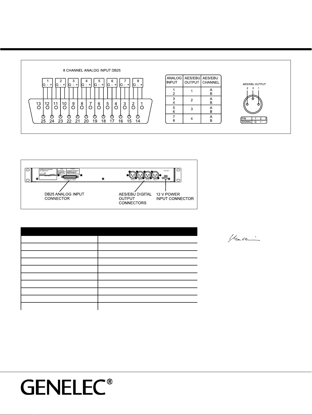
The eight-channel balanced analog input
uses a 25-pin DB25 connector wired to the
Tascam/ProTools industry standard pinout.
The digital output consists of four male XLR
connectors. Each XLR output carries two
AES/EBU digital audio channels with 24 bit
word length and 192 kHz sample rate. The
AD9200A provides the same consistent high
quality found in Genelec DSP Series loud-
speakers and subwoofers.
Connecting the AD9200A
The rack mount ears on the AD9200A can
be attached to the front or the back of the
unit. This allows the AD9200A to be rack-
installed with the front plate or the connector
panel visible in the rack. The rack ears can be
removed for table-top operation. A Pozidrive
1 screwdriver is needed for this.
No signal cables or connectors are sup-
plied with AD9200A. A 5-meter 8 x XLR-to-
DB25 cable loom is available as an option
(order code 1550-105).
When choosing an analog input signal
cable, note that the DB25 input connector is
wired to the Tascam/ProTools industry stan-
dard pinout (see Picture 1). All Tascam/Pro-
Tools industry standard cables can be used.
The threads on the connector attachment
screw posts are metric (M2.5) according to
the Tascam standard. When making your
own cable make sure you use screws with
the correct thread.
Connect the provided FW74010/12 12 V
power supply cable to the AD9200A and the
power supply mains cable to a mains connec-
tor
.
Using the AD9200A
Allow the AD9200A to warm up for approxi-
mately two minutes after switching-on. Noise
level on the digital outputs can be higher
immediately after switch-on. Noise will
decrease and disappear during the warm-
ing-up period due to internal AD converter
circuit calibration.
The AD9200A is equipped with two indica-
tor LED lights on the front and back panels.
These show the same information. A green
light indicates a normal powered-on condi-
tion. Short flashes of red indicate analogue
input clipping. Reduce the input signal level
until the indicator LED light stays green.
Maintenance
No user serviceable parts are within the unit.
Any maintenance or repair of the AD9200A
should only be undertaken by qualified ser-
vice personnel.
Safety considerations
Although the AD9200A has been designed
in accordance with international safety stan-
dards, the following warnings and cautions
should be observed to ensure safe opera-
tion and to maintain the AD9200A under safe
operating conditions:
• Servicing and adjustment must only be
performed by qualified service personnel.
The unit must not be opened by the user.
• The AD9200A may only be used with the
FW74010/12 power supply it is delivered
with. No other types of power supply are
accepted.
• Do not expose the AD9200A or its power
supply to water or moisture. Do not place
any objects filled with liquid, such as
vases on or near them.
• Keep naked flame sources such as
candles away from the AD9200A and
its power supply.
• The space adjacent to the converter
must either be ventilated or sufficiently
large to dissipate heat so that the ambient
temperature does not rise above 35
degrees Celsius (95°F).
• Note that the AD9200A is not completely
disconnected from the AC mains service
unless mains plug or appliance coupler
of the power supply is disconnected
from the mains outlet. Ensure that the
plug or appliance coupler of the power
supply is readily operable and easily
accessible for doing this.
Guarantee
This product is guaranteed for a period of two
years against faults in materials or workman-
ship. Refer to supplier for full sales and guar-
antee terms.
Analog input 8 channel balanced DB25 Tascam pin out
Input clip level +21.5 dBu
Digital audio format AES/EBU (AES3), 24 bits, 192 kHz
Dynamic range 110 dB (lin)
Dimensions H x W x D 43 x 483 x 105 mm (111/16 x 19 x 41/8”)
Weight 2 kg (4.4 lb)
External power supply type FW74010/12
Mains voltage 100 – 240 VAC, 50 – 60 Hz
Supply voltage 12 VDC
Power consumption < 7 W
EC Declaration of Conformity
This is to certify that the Genelec AD9200A Analog to
Digital Converter conforms to the following standards:
Safety:
IEC 60065:2001 + A1:2005 / EN 60065:2002 + A1:2006
EMC:
EN 55013:2001 + A1:2003
EN 55020:2002 + A1:2003
EN 61000-3-2:2000
EN 61000-3-3:1995 + A1:2001
The product herewith complies with the requirements
of The Low Voltage Directive 73/23/EEC and EMC
Directive 2004/108/EC
Signed:
Ilpo Martikainen
Position: Chairman of the Board
Date: 26-October-2007
Picture 1. Connector pin sequence: “G” ground reference, “-” balanced signal, inverting line, “+” balanced signal, non-inverting line.
Pin 13 is not connected.
www.genelec.com
Genelec Document D0083R006 (750-AD9200A). Copyright Genelec Oy 11.2007. All data subject to change without prior notice
International enquiries:
Genelec, Olvitie 5
FIN-74100, Iisalmi, Finland
Phone +358 17 83881
Fax +358 17 812 267
Email [email protected]
In the U.S. please contact
Genelec, Inc., 7 Tech Circle
Natick, MA 01760
Phone +1 508 652 0900
Fax +1 508 652 0909
Email [email protected]
In China please contact:
Beijing Genelec Audio Co. Ltd.
Jianwai SOHO, Tower 12, Room 2306
39 East 3rd Ring Road
Chaoyang District
Beijing 100022, China
Phone +86 10 5869 7915,
Fax +86 10 5869 7914
In Sweden please contact
Genelec Sverige
Ellipsvägen 10B
P.O. Box 5521, S-141 05 Huddinge
Phone +46 8 449 5220
Fax +46 8 708 7071
Email [email protected]
Picture 2. AD9200A connector panel layout
Compliance to FCC Rules
This device complies with Part 15 of the FCC Rules. Opera-
tion is subject to the following two conditions: (1) this device
may not cause harmful interference, and (2) this device must
accept any interference received, including interference that
may cause undesired operation.Changes or modifications
not expressly approved by the party responsible for compli-
ance could void the user’s authority to operate the equip-
ment.
AD9200A Operating Manual
AD9200A system specificAtions
Other Genelec Media Converter manuals


