Genelec 9301B User manual

Genelec 9301B
Multichannel AES/EBU Interface
Operating Manual
9301B

Genelec 9301B Multichannel AES/EBU Interface
Introduction
Congratulations and thank you for
purchasing the Genelec 9301B multichannel
AES/EBU interface.
This manual addresses the setting up and
use of the Genelec 9301B multichannel AES/
EBU interface intended for use with 7300
Series subwoofers.
73xx Smart Active Monitoring (SAM)
subwoofers have one AES/EBU digital
input. The 9301B expands that digital audio
connectivity to 16 channels, to create, for
example, a 9.1.6 configuration including
the additional low frequency eects (LFE)
channel.
Genelec's energy-saving Intelligent Signal
Sensing (ISS) function automatically puts
the 9301B into a power-save state when no
AES/EBU input signal is present. The waiting
time before activation can be configured
using Genelec Loudspeaker Manager (GLM)
software. When ISS is on your monitoring
system will remain ready for action and the
9301B will consume less than one watt of
power. The interface will wake up and switch
to normal operating mode when it senses an
AES/EBU input signal.
This 9301B is supplied with:
• Mains cable
• 5 m GLM network cable
• Operating manual
Installation
We strongly recommend switching off/
disconnecting mains power from all system
devices before connecting signal cables.
Connections
The mains input supports a wide voltage
range (100-240 VAC, 50-60 Hz). If the mains
power is provided by a generator, inverter or
a low-quality UPS device, we recommend
using a harmonic filter to reduce the
unwanted harmonic distortion.
The digital audio inputs for AES/EBU
digital audio both use DB25 connectors.
If the LFE channel is in use, the interface
channel and subframe carrying the LFE
signal is assigned by the user in GLM.
The digital audio output for the monitors
uses one DB25 connector to deliver 16
channels of AES/EBU format audio. The
output signals are bit-to-bit copies of the
digital input signals, so the outputs retain the
original signal quality without modication.
When used, the LFE signal is output through
the same DB25 connector, meaning that
the LFE channel content is available for any
device connected to this output.
The digital audio output for the subwoofer
is a single male XLR connector, which uses
an AES/EBU cable to carry the sum of all
the main channel inputs over one AES/EBU
subframe and the LFE channel, if used, over
the other AES/EBU subframe. A GLM Kit
and Genelec Loudspeaker Manager (GLM)
software is required in order to use the
9301B with 7300 Series subwoofers.
The AES/EBU output on 7300 Series
subwoofers enables the daisy-chaining of
additional SAM subwoofers to increase
the capacity of the system's low frequency
acoustic output (SPL). To make this possible,
GLM software will align the playback of the
complete subwoofer system with the rest of
the monitoring system.
The 9301B includes two GLM Network
connectors for management using Genelec
Loudspeaker Manager (GLM) software.
Input cabling
Digital Audio Workstations and other
professional digital audio sources frequently
offer DB25 connectors using AES59
standard compatible pinouts for digital
audio. These typically feature four inputs
and four outputs, delivering up to 8 channels
of digital audio in and 8 channels of digital
out. This pinout is also known as the Tascam
digital audio pinout. The AES59 standard
also offers a configuration to deliver 16
channels of digital audio in one direction,
used in the output DB25 connector of 9301B
(see 'Output cabling' section below).
The 9301B uses two AES59 compatible
DB25 connectors for input, each receiving
up to 8 channels of digital audio from the
digital audio source, typically connected with
DB25-to-DB25 cables connecting the audio
source digital outputs to the receiving device

Figure 1. The principle of connecting the 9301B
Figure 2. Functional block diagram of the 9301B and the sample rate converter (SRC)
GLM ADAPTER
= AES/EBU DIGITAL CABLING
= GLM NETWORK CABLING
AUDIO SOURCE
MAINS INPUT
AES IN 14 AES IN 58 AES OUT 18
SUBWOOFER
LINK
AES OUT
DIGITAL
OUT
DIGITAL
IN
DIGITAL
IN
GLM
NETWORK
AES IN 58 AES IN 14
AES OUT 18
digital inputs (see Fig. 3). Please check for
this specically when purchasing the cable.
If you'd also like to access the incoming
digital audio lines on your audio source's
DB25 connectors, a combination of two
break-out cables oering XLR connectors
can be used between your audio source
and each 9301B DB25 input. This makes
the audio source device's DB25 connectors
available for incoming connections and this
is also a safe choice as you will always have
the possibility to connect specic outputs at
the digital audio source to the digital audio
inputs in 9301B. For example, Avid cable
type DigiSnake DB25-XLR M+F AES/EBU is
suitable for this.
Output cabling
The AES59 standard oers a conguration
to deliver 16 channels of digital audio in
one direction. This is in the output DB25
connector of 9301B. The audio output
Figure 3. Digital audio input cable
pin-out.
Figure 4. Digital audio output cable
pin-out.
in 9301B is intended for connections to
monitors. The recommended cable for
this connection is an 8 x XLR male fan-out
cable with AES59 pin-out, also known as
the Tascam analogue pin-out. For example
an Avid cable type DB25-XLRM DigiSnake
can be used. Typically AES/EBU XLR-to-
XLR cables are required to extend the signal
onwards to the monitors.
Connector pinouts
The input connector pinouts of the 9301B's
two DB25 audio input connectors follow the
AES59 standard compatible pinout shown
in Figure 3. This features four inputs and
four outputs, delivering 8 channels of digital
audio in and 8 channels of digital out. This
pinout is also known as the Tascam digital
audio pinout.
The AES59 standard oers a conguration
to deliver 16 channels of digital audio in one
direction. The output connector pin-out
of the 9301B's single DB25 out is shown
below. This pinout is compatible with the
AES59 standard. This pinout is also known
as the Tascam analogue output pinout. We
strongly recommend that a high-quality AES/
EBU digital audio cable is used.
Controls and Adjustments
The 9301B's front panel features a mains
power switch with power-on light and eight
active-connection indicator lights for AES/
EBU inputs, each carrying two channels of
audio.
The 9301B is completely set up using
Genelec Loudspeaker Manager (GLM™)
software. Please refer to the ‘Use With GLM
Management Network’ section below for
details.
While editing the 9301B settings in GLM,
the interface's power-on light will blink
continuously. A lit input light indicates a
valid AES/EBU input. If an input light is o,
there is an AES/EBU data issue or there is no
valid AES/EBU input. See Table 1 for a list of
indicator lights and their functions.
Use With GLM™
Management Network
The 9301B is set up using Genelec
Loudspeaker Manager GLM™ software,
using GLM's Management Network. More
information about the GLM is available in the
SAM System Operating Manual.
Finally, connect to the GLM Adapter
device (see Figure 1). The connection
order of the other devices is not important.
Connect the GLM Adapter device to your
computer via USB.
• Install and run Genelec Loudspeaker
Manager (GLM) software.
All devices appear in GLM software monitor
stack. Move devices from the monitor stack
onto GLM honeycomb grid, including the
9301B. You may want to drag and drop
9301B close to the subwoofer connected to
it (see Figure 5).
When using multiple 9301Bs, you can
identify an 9301B by clicking the 9301B
icon in GLM, causing the associated 9301B
device front panel power button light to blink.
Table 1. Front panel indicator light functions
System configuration
Setup is simple and consists of the following
steps:
• Connect digital audio inputs ‘AES IN 1-4’
and ‘AES IN 5-8’.
• Connect ‘AES OUT 1-8’ to a fan-out cable
and continue with XLR-to-XLR cables to
each monitor. Please use cables intended
for carrying AES/EBU digital audio. We
strongly discourage the use of standard
analogue microphone cables as this may
reduce system performance.
• Connect the 'SUBWOOFER LINK' output
to the 'DIGITAL IN' connector on a
Genelec 7300 Series subwoofer.
• Connect CAT 5 (RJ45) cables between
the 9301B, every monitor and subwoofer.
Indicator Colour, indication Meaning
Power switch Solid green Power on, normal operation
Blinking green GLM is adjusting 9301B
Green blink every 10 s 9301B in power save mode
No light No power, power o
Input signal indicator Solid green Valid digital audio is detected and
received
No light Valid input is not detected
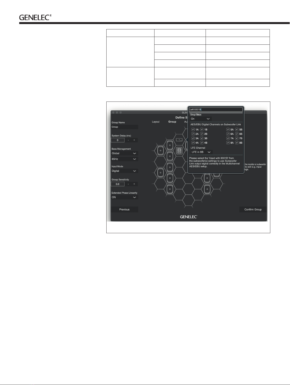
Figure 5. 9301B setup panel in GLM software.

Returning to factory settings
GLM settings stored in a 9301B can be
erased by keeping the power switch
depressed for more than 10 seconds before
releasing it again. This returns the 9301B to
its factory settings. After this, GLM software
should be used to recongure the 9301B.
Operating Environment
The 9301B is designed for indoor use
only, and the permissible ambient room
temperature is 15-35 degrees Celsius (50-
95°F) with a relative humidity of 20% to 80%
(noncondensing). If the 9301B has been
stored or transported in a cool environment
before entering a warm room, please wait
between 60 minutes before unpacking it,
as this will prevent harmful condensation.
Sufficient cooling must be ensured to
keep the 9301B within optimal operating
temperatures. No minimum clearance for
ventilation is needed around the interface.
Maintenance
There are no user serviceable parts inside
the 9301B. Maintenance or repair must only
be performed by Genelec certied service
personnel.
Guarantee
Genelec guarantees the 9301B for two
years against manufacturing faults or defects
that alter performance. Refer to the reseller
for full sales and guarantee terms.
Safety Considerations
The 9301B has been designed in
accordance with international safety
standards. To ensure safe operation, the
following warnings and precautions must be
observed:
• Servicing and adjustment must only be
performed by Genelec certified service
personnel.
• The enclosure must not be opened.
• Do not use this product with a mains
cable or mains outlet without a protective
earth (potential-equalising) connection, as
doing so may result in personal injury.
• To prevent fire or electric shock, never
expose the unit to water or moisture.
• Do not place objects filled with liquid,
such as vases, on or near the 9301B.
• The 9301B is never completely
disconnected from mains power unless
the mains cable is removed from the
device or the mains outlet.
Compliance to FCC Rules
This device complies with part 15 of the
FCC Rules. Operation is subject to both of
the following two conditions:
• This device may not cause harmful
interference.
• This device must accept any interference
received, including interference that may
cause undesired operation.
Note: This equipment has been tested
and found to comply with the limits for a
Class B digital device, pursuant to part
15 of the FCC Rules. These limits are
designed to provide reasonable protection
against harmful interference in a residential
installation. This equipment generates, uses,
and can radiate radio frequency energy
and, if not installed and used in accordance
with the instructions, may cause harmful
interference to radio communications.
There is no guarantee that interference will
not occur in a particular installation. If this
equipment does cause harmful interference
to radio or television reception, which can
be determined by turning the equipment o
and on, the user is encouraged to try and
correct the interference by one or more of
the following measures:
• Reorient or relocate the receiving antenna.
• Increase the separation between the
equipment and receiver.
• Connect the equipment into an outlet on
a circuit dierent from that to which the
receiver is connected.
• Consult the dealer or an experienced
radio/TV technician for help.
Modications not expressly approved by the
manufacturer can void the user’s authority to
operate the equipment under FCC rules.
Indicator Colour, indication Meaning
Power switch Solid green Power on, normal operation
Blinking green GLM is adjusting 9301B
Green blink every 10 s 9301B in power save mode
No light No power, power o
Input signal indicator Solid green Valid digital audio is detected and
received
No light Valid input is not detected
Setting up a 9301B in GLM:
• Select the ‘Input Signal Type’ for the
monitor Group to be ‘AES/EBU Digital’.
Then 9301B devices become active in
the group. Set the ‘AES/EBU Digital Input
Mode’ for all the connected 7300 Series
subwoofers to ‘Multichannel’.
• Select the AES/EBU inputs to enable
them.
• In the ‘LFE Channel’ drop-down, select
the AES input and subframe that carries
the LFE channel audio.
• Select the ‘+10 dB’ setting in the
subwoofer configuration if the LFE
channel audio requires a 10 dB boost
relative to the main audio channels.
When all 9301B units in the system are set to
‘Group O’ state, the ‘AES/EBU Digital Input
Mode’ in all 7300 series subwoofers switch
the AES/EBU digital stereo audio input to a
standard stereo audio input.
Acoustic calibration
To acoustically calibrate your setup, x the
measurement microphone included with
your GLM Kit onto a microphone stand
so that the microphone points upwards,
then place the microphone at the listening
position with the top positioned at the
listener’s ear height.
Follow the steps in GLM software to
calibrate your entire system. The calibration
process starts after you create a new group
preset using ‘File’ | ‘New’ menu item. An
existing group preset can be calibrated by
selecting the ‘Group Preset’ | ‘Calibrate’ meu
item.
If you wish to disconnect the computer
after calibration, save GLM calibration onto
monitors, subwoofers and 9301B interfaces
in your system. The settings can be stored
using GLM software menu item ‘Store' |
'Store the Current Group Settings’. Note
that monitors and subwoofers have a switch
that enables stored settings. This switch
must be set to ON for operating the system
with the stored settings. After removing the
GLM network cable and powering the 9301B
and monitors o and on again enables the
stored settings. We strongly recommend
using GLM software and keeping the GLM
network connected for the full exibility of
the monitoring system.

SPECIFICATIONS
Weight 2 kg (4.4 lbs)
Dimensions:
Height
Width
Depth
44 mm (1 11/16 in)
466 mm (18 3/8 in)
211 mm (8 5/16 in)
Mains voltage 100...240 VAC (50...60 Hz)
Mains tolerance +/- 10 %
Power consumption
ISS power saving mode
Idle
Full operation
1 W
1 W
2 W
Digital audio input connectors 4 XLR female
Digital audio input impedance 110 Ohm
Digital audio output connectors 5 XLR male
Digital audio format AES/EBU (AES3-2003)
Can also be used with S/P-DIF and AES3id
signals when impedance converters are
used
Digital audio word length Minimum 16 bits, maximum 24 bits.
Fixed point, AES/EBU format
Digital audio sample rate Minimum 32 kHz, maximum 192 kHz.
Supports single-wire AES/EBU audio,
does not support dual wire AES/EBU audio


Genelec 9301B Multichannel AES/EBU Interface
Genelec Document D0206R001. Copyright Genelec Oy 2.2023. All data subject to change without prior notice www.genelec.com
International enquiries:
Genelec, Olvitie 5
FIN-74100, Iisalmi, Finland
Phone +358 17 83881
Fax +358 17 812 267
Email [email protected]
In the U.S. please contact:
Genelec, Inc., 7 Tech Circle
Natick, MA 01760, USA
Phone +1 508 652 0900
Fax +1 508 652 0909
Email [email protected]
In China please contact:
Beijing Genelec Audio Co.Ltd
Room 101, Building B33,
Universal Business Park,
No.10 Jiuxianqiao Road,
Chaoyang District,
100015 Beijing, China
Phone +86 (10) 5823 2014
+86 400 700 1978
Email [email protected]
In Sweden please contact
Genelec Sverige
Tureholmsvägen 12
125 35 Älvsjö
Sweden
Phone +46 8 449 5220
Email [email protected]
In Japan, please contact:
Genelec Japan Inc.
2-22-21 Akasaka, Minato-ku
07-0052, Tokyo
Phone +81-3-6441-0591
Email [email protected]
Table of contents
Other Genelec Recording Equipment manuals


