Roger UT-4DR User manual

Roger Access Control System
Communication interface UT-4DR
Firmware version : 1.0.2
Document version: Rev. B

UT-4DR v1.0 Instruction manual Rev.B 2012-09-21
Strona 2z 12
Contents
1. Description and specification........................................................................................ 3
1.1 Characteristics............................................................................................................... 3
1.2. Using the interface in RACS system................................................................................. 3
2. Installation.................................................................................................................... 4
2.1 Terminals and connection diagram .................................................................................. 4
2.2 LED indicators ............................................................................................................... 5
2.3 Power supply ................................................................................................................ 5
2.4 Input/Output lines ......................................................................................................... 6
2.5 RS485 communication bus.............................................................................................. 7
2.6 Ethernet interface.......................................................................................................... 7
2.7 Installation guidelines .................................................................................................... 8
3. Configuration................................................................................................................. 8
3.1 Configuration using web browser..................................................................................... 8
3.2 Configuration using Telnet protocol.................................................................................. 9
3.3 Memory reset...............................................................................................................10
3.4 Firmware update procedure ...........................................................................................11
4. Technical specification ................................................................................................ 12
5. Ordering information................................................................................................... 12
6. Product history............................................................................................................ 12

UT-4DR v1.0 Instruction manual Rev.B 2012-09-21
Strona 3z 12
1. DESCRIPTION AND SPECIFICATION
1.1 Characteristics
UT-4DR interface is a device enabling communication with RACS 4 access control system through
10/100 BaseT Ethernet network. Apart from this main function, it is equipped also with 4 universal
Input/Output lines which can be managed using web browser or by means of Telnet protocol. This
feature gives possibility to use the device in other application (not in RACS 4 system) as a remote
I/O port, managed by means of computer network.
UT-4DR electronic module is put into plastic enclosure dedicated for mounting onto standard DIN
rail 35mm.
Main features of UT-4DR interface:
TCP/IP communication interface for RACS 4 system
LAN/WAN 100/10Mbit/s Ethernet
4 universal I/O lines managed by web browser or Telnet protocol
10-15VDC power supply
Plastic enclosure for 35mm DIN rail
CE mark
Note: it is not possible to use UT-4DR interface as a virtual serial port in other applications
requiring communication with a serial device connected to Ethernet network.
1.2. Using the interface in RACS system.
UT-4DR can be used for programming single access controller of PR series, or for work with
network access control system consisting of many controllers connected to RS485 communication
bus. UT-4DR enables two way data transmission between access control devices and PR Master
managing software.
RACS access control system software is ready to work with networks (subsystems) connected via
computer network. During system configuration in PR Master software, both communication port
type (TCP/IP) and communication interface device (UT-4DR) have to be chosen to establish
communication. Basing on these settings the software will automatically set transmission time
parameters to ensure efficient communication between managing PC computer and managed
network of RACS system.
Note: Using UT-4DR requires PR Master software in version 4.4.6.xxx or higher.
Note: It is not recommended to use UT-4DR interface to connect with subsystems containing
PR201 and PR301 access controllers. Any errors occurring in data transmission during configuration
of these controllers will cause them to hang up and will require manual reset.

UT-4DR v1.0 Instruction manual Rev.B 2012-09-21
Strona 4z 12
Fig.1 Configuration of RACS access control subsystem equipped with UT-4DR interface.
2. INSTALLATION
2.1 Terminals and connection diagram
The module is offered in plastic enclosure dedicated for mounting onto standard DIN rail 35mm. All
electrical connections have to be made with disconnected power supply voltage.
Table 1. UT-4DR terminals
Terminal Description
+12V Power supply
GND Ground
A RS485 bus, line A
B RS485 bus, line B
GND RS485 bus Ground
IO4 I/O line #4
IO3 I/O line #3
IO2 I/O line #2
IO1 I/O line #1

UT-4DR v1.0 Instruction manual Rev.B 2012-09-21
Strona 5z 12
Fig.2 UT-4DR proposed connections diagram in RACS system.
2.2 LED indicators
UT-4DR is equipped with two LED diodes indicating actual state of a device (Fig.2). Bi-color LED
LINK informs about currently going transmission in RS485 bus, where green color means data
sending, while red data receiving by a module.
LED STATUS (orange) informs about current device state:
On – normal work
Blinks – memory or configuration error (memory reset required, see point 3.3)
Off – lack of or error in LAN connection
2.3 Power supply
The device is supplied from 12VDC voltage (acceptable voltage range 10-15VDC) which can be
taken from access control system or from separate power supply source. In this second case it is
essential to make electrical connection between power supply ground and RACS system RS485 bus
ground (Fig.2).

UT-4DR v1.0 Instruction manual Rev.B 2012-09-21
Strona 6z 12
2.4 Input/Output lines
UT-4DR has 4 lines of general purpose indicated as IO1...IO4. These lines can be used individually
as independent inputs or outputs. They can work with maximal voltage of 15VDC (in comparison to
device’s power supply ground) no matter if configured as input or output. Input lines are activated
by low logical state (connecting the line to ground). Output lines in normal state represent high
impedance while in active state short circuit connected voltage with ground. Maximal current which
can be switched by output lines is limited to 0.5A. If this value is exceed, an internal overload
protection is activated, switching off all output lines. Protection is deactivated when source of
overload is removed. In overload state UT-4DR stops its normal work.
I/O lines electrical structure is shown on Fig.3.
Fig.3 UT-4DR module Input/Output lines electrical structure.
Output managing and input state reading is possible by means of device’s WWW page (GPIO tab)
which contains the following elements:
IO#
Line number
Custom Name
Each line can be given a name (comment)
Custom Direction
Enables choice between input and output function for a certain line
Current Input State
Visualization of input lines state (activation makes the lines checkbox marked)
Set Output
Enables to switch on and off an output line.

UT-4DR v1.0 Instruction manual Rev.B 2012-09-21
Strona 7z 12
Periodic
Option causing automatic web page refreshing in case of any settings or I/O lines state changing,
without a need of manual refresh. Without this option checked, page refreshing can be done
manually with button Refresh or with adequate web browser’s option.
Any changes made in Input/Output configuration should be saved in module’s memory using Save
settings button.
Fig.4 I/O lines configuration tab in module’s embedded web page.
2.5 RS485 communication bus
RS485 bus consists of two signal wires (A and B) and of power supply ground GND. In RACS 4
system topology of RS485 communication bus is fairly flexible and it is allowed to make tree
structures, star topologies as well as combination of these two. It is also not required to apply
termination resistors at any end of communication bus. In most cases communication will work
without any problems for any types of cables applied (telephone pair, twisted pairs shielded or
unshielded). It is however recommended to use unshielded twisted pair computer cable (UTP).
Using shielded cables is recommended only in case of strong electro-magnetic fields presence
causing noise in transmission line. RS485 communication standard applied in RACS 4 system
guarantees proper communication for up to 1200 meters long bus (measured between two most
distant devices) and is very resistant to noise.
2.6 Ethernet interface
UT-4DR works with Ethernet computer networks of 100 and 10Mbit/s speed. In most cases
unshielded twisted pair cable (UTP) is good enough as physical communication medium, however in
case of strong E-M noise presence it is recommended to use shielded cable (FTP).
By default every UT-4DR interface is in DHCP mode. In case of direct connection between PC
computer and UT-4DR module (such situation takes place usually for local module configuration
before connecting it to LAN network) there is a possibility to deactivate DHCP in the module. To do
that, it is required to put jumper as shown in Fig.5. In this setting the module will only use static IP
address stored in memory (factory default 192.168.0.38). If in final configuration the module is to
use DHCP the jumper has to be removed. If module’s IP address has to be changed it can be done
using module’s configuration panel available via web browser (see point 4.1).

UT-4DR v1.0 Instruction manual Rev.B 2012-09-21
Strona 8z 12
Note: Depending on Ethernet network settings, it may take up to 2-3 minutes until UT-4DR obtains
DHCP configuration data. In case of lack of communication with the module, wait several minutes
and try again.
Fig.5 The way of placing jumper for DHCP deactivation.
2.7 Installation guidelines
The module should be installed in a way ensuring easy access to terminals and cables
All electrical connections should be made without power supply voltage
All devices connected to access control system communication bus (readers, extension modules,
access controllers, interfaces) should have common ground
In case of strong E-M noise presence it is recommended to use shielded twisted pair cable FTP
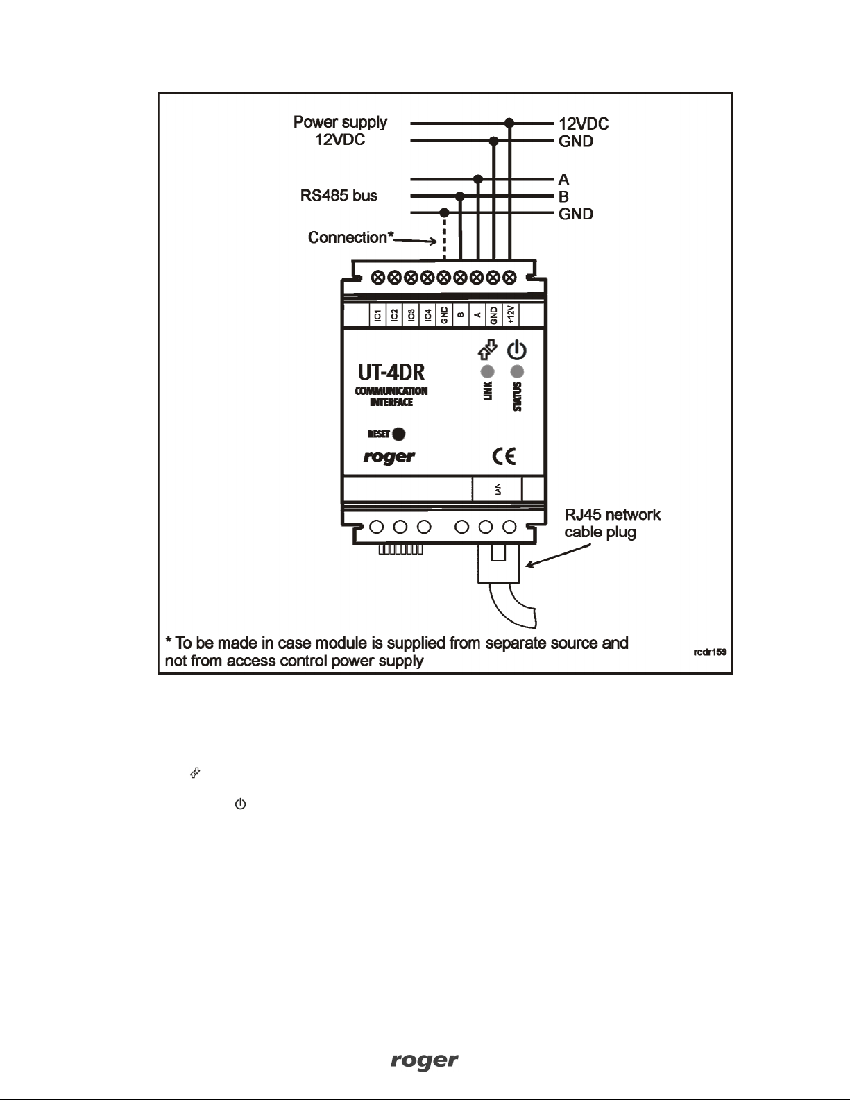
If UT-4DR module is supplied from an independent power source (separate from RACS system)
it is strongly suggested to make a connection between RS485 and UT-4DR module grounds
(Fig.2)
3. CONFIGURATION
3.1 Configuration using web browser
It is possible to configure UT-4DR interface using its embedded WWW page. To do this, please type
module’s IP address (ex.192.168.0.38) in web browser address field, and log in as a default user
with the following parameters:
User: root
Password: dbps
After logging in, the following configuration options are available :
Network
Enables changing UT-4DR module’s network settings. Activating an option Obtain LAN IP
Address from DHCP Server causes automate awarding IP address to the module. When option
deactivated, it is possible to set manually static IP address, subnet mask, default gateway, DNS
server address and TCP port for communication with UT-4DR.
Note: improper network settings can cause lack of communication with UT-4DR module. In this
case memory reset procedure has to be made.
Password
Enables changing user password, requires introducing new password and confirming it.
GPIO
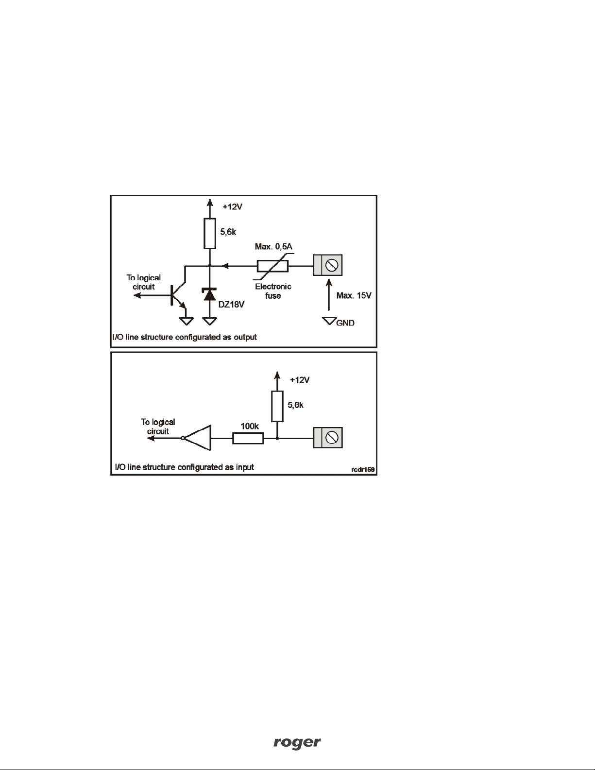
Enables configuration and managing of universal I/O lines (see point 2.4).
TCP Stat
Tab containing statistical data regarding connection with UT-4DR interface
FW Upgrade
Enables UT-4DR module’s firmware upgrade (see point 3.4)

UT-4DR v1.0 Instruction manual Rev.B 2012-09-21
Strona 9z 12
Mobile Web GUI
This option enables to switch from standard module’s web site view to mobile devices view (tablets,
smartphones). The website for mobile devices contains analogical set of functions but without TCP
statistics (TCP Stat) and possibility to module’s firmware change (FW Upgrade). The view of mobile
devices website is shown below in Fig.6.
Restart
Zakładka zawierająca przycisk Reboot służący do zdalnego restartu modułu UT-4DR.
To go back to main configuration window use button with house picture placed in top right corner
of each configuration window.
Fig.6 Mobile devices website view in UT-4DR
3.2 Configuration using Telnet protocol
In order to log in to the module, please type in command line : telnet <module’s IP address>, ex.
telnet 192.168.0.38. Then please log in as a default user (user: root, password: dbps). While
logged in, after typing help command, a list of available commands with description will appear
(Fig.7).

UT-4DR v1.0 Instruction manual Rev.B 2012-09-21
Strona 10 z 12
Fig.7 Configuration using Telnet.
Note: Described above procedure of connecting to UT-4DR module using Telnet protocol may vary
depending on used Telnet client application. In Windows Vista and Windows 7 operations systems
Telnet client is deactivated as a default. It has to be activated manually before first attempt of
connection with UT-4DR.
3.3 Memory reset
In order to get back to UT-4DR module’s factory settings it is required to stop any communication
with module (web browser and/or Telnet), put two jumpers as shown in Fig.8 and press RESET
button in the front panel. Reset procedure lasts about 5 seconds and when it is finished LED
STATUS diode blinks 3 times indicating success of the operation. Both jumpers has to be
removed after that. The device is ready to work in DHCP mode. In case of local configuration, after
putting jumper as shown in Fig.5 the module has default static IP address (192.168.0.38).
Note : After memory reset IO lines configuration remains unchanged. In order to reconfigure them
it is required to establish connection with the module and change IO lines configuration manually.
Fig.8 The way of placing jumpers in memory reset procedure.

UT-4DR v1.0 Instruction manual Rev.B 2012-09-21
Strona 11 z 12
3.4 Firmware update procedure
To make UT-4DR module’s firmware upgrade, please log into embedded web page of the module,
using web browser. In Firmware Upgrade tab, press Wybierz button to choose on your
computer a file containing new firmware. Press Send button to send file to the UT-4DR module and
change its firmware. During firmware modification all I/O lines are deactivated. After sending new
firmware to module, please reset it by pressing Reboot button in the web page. During firmware
actualization process the device can stop answering to any attempt of communication, which does
not mean troubles in functioning. If however lack of communication lasts longer than 5 minutes,
please reset the device by pressing Reset button on its front panel and try again whole procedure.
After successful firmware update the module is ready to work with settings saved in memory before
firmware update procedure.

UT-4DR v1.0 Instruction manual Rev.B 2012-09-21
Strona 12 z 12
4. TECHNICAL SPECIFICATION
Parameter Value
Supply voltage 10...15 VDC
Current consumption Average 55 mA @ 12V DC,
Environmental class
Class II, indoor conditions, temp.:- 10°C +40°C, relative humidity: 0 -
75% (no condensation)
Dimensions 62x85x73mm (WxHxD); 3,5 DIN rail unit
Weight Approx. 110g
Certificates CE
5. ORDERING INFORMATION
Product Description
UT-4DR Communication interface
6. PRODUCT HISTORY
Version Firmware Data Description
UT-4DR v1.0 1.0.0 09/2011 First commercial version of the product
UT-4DR v1.0 1.0.2 07/2012 Remote reset added, mobile GUI added
This symbol placed on a product or packaging indicates that the
product should not be disposed of with other wastes as this may
have a negative impact on the environment and health. The user is
obliged to deliver equipment to the designated collection points of
electric and electronic waste. For detailed information on recycling,
contact your local authorities, waste disposal company or point of
purchase. Separate collection and recycling of this type of waste
contributes to the protection of the natural resources and is safe to
health and the environment. Weight of the equipment is specified in the
document.
Other manuals for UT-4DR
1
Table of contents
Other Roger Recording Equipment manuals