MP113
MP113GMU Rev B 7
The Status Information is a current snapshot of MP113’s operation and will therefore change during the oper-
ation of MP113.
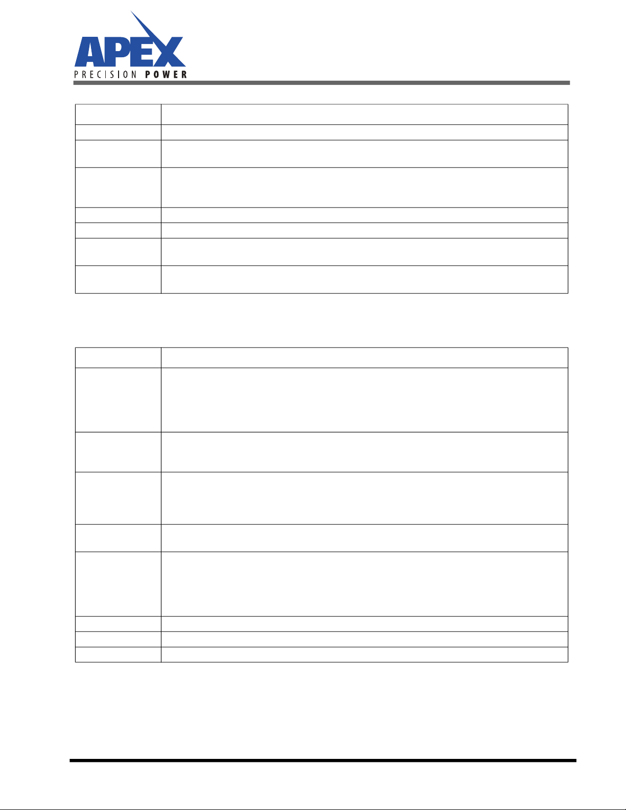
Item Explanation
Firmware Revision Date code of the current firmware built
Number of Colors Maximum number of colors the MP113 can handle. Please also read the chapter “single or Dual
Color Print Head”
Maximum Voltage
Maximum output voltage MP113 cab handle, provided that a proper supply voltage is provided.
Please check the data sheet for details on the output voltage swing to determine the supply volt-
age headroom needed for the output voltage
D/A Clock D/A converter update rate
PWM Clock Internal operating clock of the waveform timer
Max Waveform
Length The maximum length of a waveform MP113 can output
Buffer Size (RX/TX) Communication buffer size. This information is helpful if you decide to develop your own commu-
nication software
Item Explanation
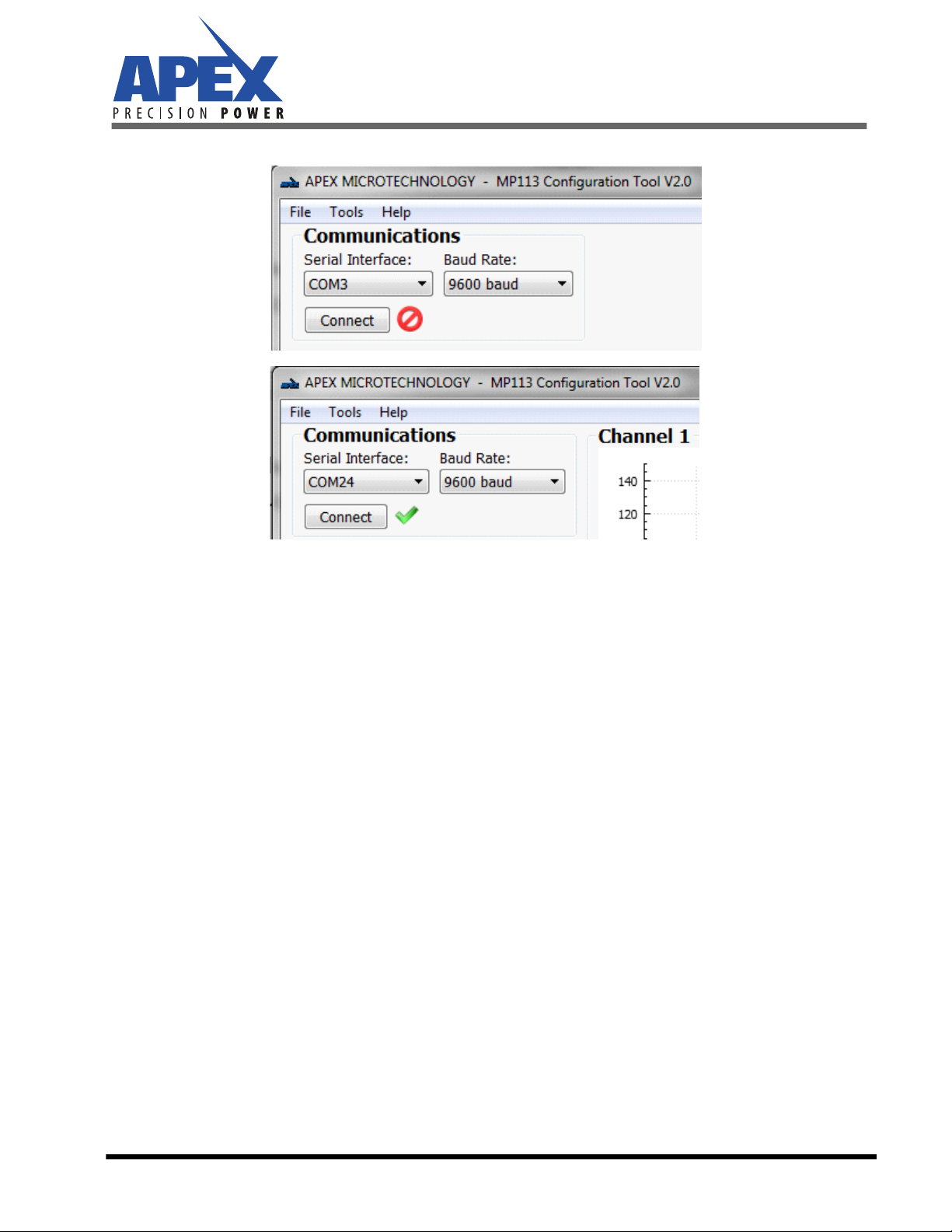
Status
“Offline” or “Online”. You can click the “Online” button to change the status. Note that MP113
can only go online if valid waveform data is available.
MP113 ignores all input signals to the MP113 if it is either in offline mode or if emulation mode is
active.
MP113 only responds to requests for waveform output when in online mode.
Current Color
Mode
Number of colors the MP113 currently handles. This can be the same or less than the maximum
number of colors MP113 can handle. Please also read the chapter “Single or Dual Color Print
Head”
Waveform Valid
No: MP113 does not have valid waveform data. If you have a MP113 that can handle 2 colors, you
need to download waveform for both colors, even if MP113 is used in single color mode.
MP113 can’t go online if no valid waveform data is found.
Yes: MP113 has valid waveform data.
Waveform Length Length of the current waveform. If you have a MP113 that can handle 2 colors, this is the longer
of the two waveforms.
Emulation Mode
Off: MP113 is controlled by the input signals to the MP113 board (card edge connector)
On: MP113 ignores all input signals to the MP113 board. It is controlled by the graphical user
interface only.
When “Emulation Mode” is on and MP113 Operation Status is “Online”, the print pulse button
appears below this table.
FPGA Status Coded Information on the FPGA status. This is provided for diagnostic purposes only.
Refresh Button Update the MP113 Status information
+VS, TA,TB MP104 temperature sensor in degrees Celsius. Supply voltage information in Volts.