Genelec 6010A User manual
Loudspeaker placement
Desktop Positioning
1 2 3
ON
OFF
Desktop Control

Loudspeaker placement
Desktop Positioning
Loudspeaker Angle and Distance
Loudspeaker Angle and Distance
LR
C
LS RS
LS RS
LR
C
Listening Distance
1'6" 6'6"
Splitting the RCA cable

Connecting the 6010A
PRE OUT
PREAMPLIFIER
LINE OUT
R
LSPEAKERS (8
RCA
RCA MINIJACK
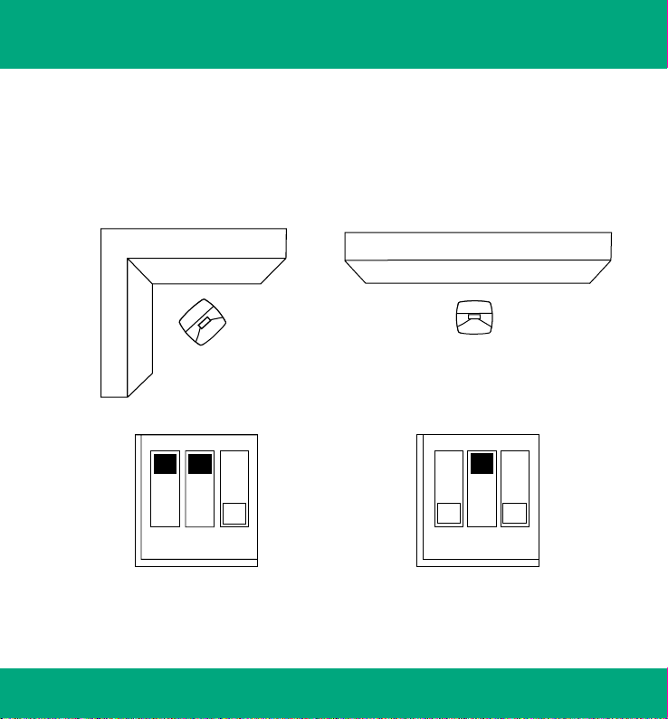
Using Tone Controls
Against a wall
ON
OFF
1 2 3
-6 dB Bass tilt
1 2 3
ON
OFF
-4 dB Bass tilt
Corner

6010A
Operating Manual 2-7
Betriebsanleitung 8-13
Manuel d´utilisation 14-19
Käyttöohje 20-25
Bruksanvisning 26-31

English 1
6010A
Active Monitoring System
General description
The bi-amplified Genelec 6010A is an extremely
compact two way active loudspeaker designed for
home theaters and professional multimedia applica-
tions. As an active loudspeaker, it contains drivers,
power amplifiers, active crossover filters and pro-
tection circuitry. The MDE™ (Minimum Diffraction
Enclosure™) loudspeaker enclosure is made of die-
cast aluminium and shaped to reduce edge diffrac-
tion. Combined with the advanced Directivity Control
WaveguideTM (DCWTM), this design provides excellent
frequency balance in difficult acoustic environments.
If necessary, the bass response of the 6010A’s can
be extended with a Genelec 5040A subwoofer.
Packing contents
Each 6010A is supplied with a wall bracket, a mains
cable, a 3.5 mm Jack to 2 x RCA signal cable, an
RCA to RCA signal cable, this operating manual and
a quick setup guide. After unpacking, place the loud-
speaker in its required listening position.
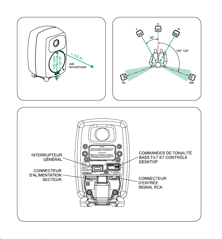
Mounting considerations
Align the loudspeakers correctly
Always place the loudspeakers so that their acoustic
axes converge at ear height at the listening position
(see Figures 1 and 2). Only vertical placement of
loudspeakers is preferred, as it minimises acousti-
cal cancellation problems around the crossover
frequency.
Maintain symmetry
Check that the loudspeakers are placed sym-
metrically and at an equal distance from the
listening position. If possible, place the sys-
tem so that the listening position is on the cen-
terline of the room and the loudspeakers are
placed at an equal distance from the centerline.
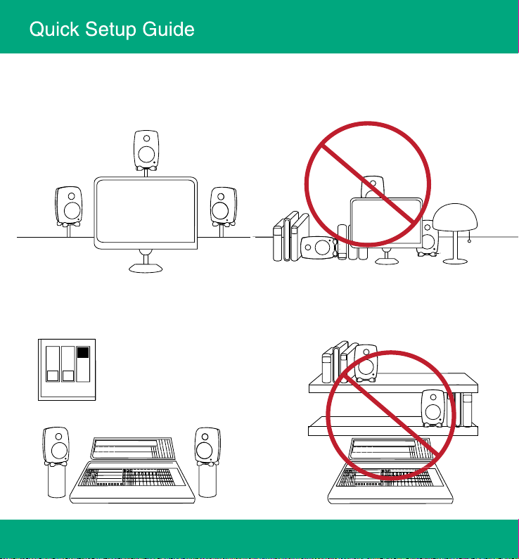
Minimise reflections
Acoustic reflections from objects close to the loud-
speakers like desks, cabinets, computer monitors
etc. can cause unwanted colouration and blur-
ring of the sound image. These reflections can
be minimised by placing the loudspeaker clear of
such surfaces.
Minimum clearances
Sufficient cooling for the amplifier and functioning of
the reflex port must be ensured if the loudspeaker is
installed in a restricted space such as a cabinet or
integrated into a wall structure.
The surroundings of the loudspeaker must al-
ways be open to the listening room with a minimum
clearance of 2.5 centimeters (1”) behind, above
and on both sides of the loudspeaker. The space
adjacent to the amplifier must either be ventilated
or sufficiently large to dissipate heat so that the
ambient temperature does not rise above 35 de-
grees Celsius (95°F)
Operating Manual
2 English
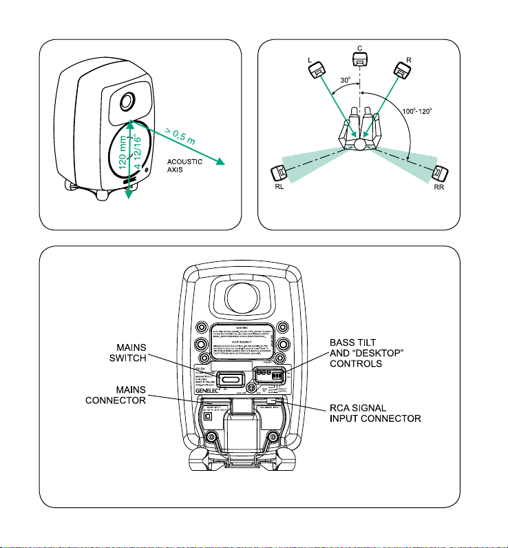
Figure 1. Location of the acoustic axis
Figure 3. Control and connector layout on the rear panel of a 6010A.
Figure 2. Correct alignment of the loudspeakers
in a 5-channel system.

English 3
Table 1: Suggested tone control settings for differing acoustical environments
Connections
Connect the loudspeaker to a mains connection
with the supplied mains cable.Check that the loud-
speaker and the signal source are powered off.
The 6010A has an unbalanced RCA 10 kOhm
audio input connector. The signal cables provided
with the loudspeaker allow it to be connected to
a line level audio source with either 3.5 mm Jack
or RCA type audio connectors. Suitable audio
sources are preamplifiers, computer sound cards,
portable audio players, “PRE OUT” connectors on
a Home Theater receiver etc.
As an active loudspeaker, the 6010A contains
its own amplifiers, no separate power amplifier is
needed. Never connect the 6010A to the loud-
speaker outputs of a power amplifier or an inte-
grated amplifier or receiver. Once the connections
have been made, the loudspeakers are ready to
be switched on.
Controls
The input sensitivity of the 6010A can be
matched to the output of the audio source by
adjusting the “LEVEL” trim on the rear panel with
a screwdriver.
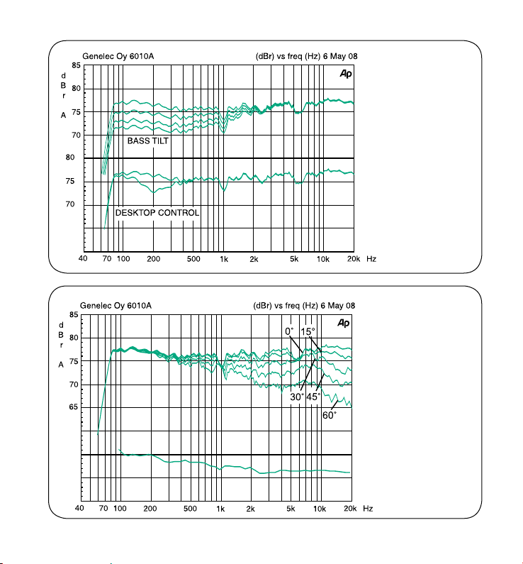
The frequency response of the Genelec 6010A
can be adjusted to match the acoustic environment
by setting the tone control switches on the rear
panel. The controls are “Bass Tilt” and “Desktop
Control”. Table 1 shows some examples of typical
settings in various situations. Figure 4 shows the
effect of the controls on the anechoic response.
The factory setting for all tone controls is “OFF”
to give a flat anechoic response. Always start ad-
justment by setting all switches to “OFF” position.
Measure or listen systematically through the dif-
ferent combinations of settings to find the best fre-
quency balance.
Bass Tilt
The Bass Tilt control offers three attenuation levels
for the bass response of the loudspeaker, usually
necessary when the loudspeakers are placed near a
wall or other room boundaries.The attenuation levels
are -2 dB (switch 1 “ON”), -4 dB (switch 2 “ON”) and
-6 dB (both switches “ON”).
Loudspeaker Mounting Position Desktop Bass Tilt
Flat anechoic response OFF OFF
Free standing in a damped room OFF OFF
Free standing in a reverberant room OFF -2 dB
Near to a wall OFF -6 dB
Near field on a reflective surface ON (-4 dB @ 200 Hz) -2 dB
In a corner or a cabinet OFF -6 dB

4 English
Desktop Control
The “Desktop” low frequency control (switch
3) attenuates the bass frequencies around
200 Hz by 4 dB. This feature is designed to com-
pensate for the boost often occurring in this fre-
quency range when there is a table or similar
horizontal surface between the listener and the
loudspeaker.
Mounting options
The 6010A offers several mounting options: The
Iso-Pod™ (Isolation Positioner/Decoupler™) vi-
bration insulating table stand allows tilting the
loudspeaker for correct alignment of the acous-
tic axis. A rigid wall bracket provided with the
6010A allows suspending the loudspeaker on
a wall in two different angles. On the rear of the
loudspeaker is a 3/8” UNC threaded hole com-
patible with standard microphone stands and
a wide range of Genelec accessories. On the
rear there are also three pairs of threaded holes
compatible with Omnimount®, VESA and Sanus
brackets. For a full list of available options, please
consult Genelec’s accessories catalogue at www.
genelec.com or contact your Genelec dealer.
Maintenance
No user serviceable parts are to be found within
the amplifier unit. Any maintenance or repair of the
6010A unit should only be undertaken by qualified
service personnel.
Safety considerations
Although the 6010A has been designed in accord-
ance with international safety standards, the fol-
lowing warnings and cautions should be observed
to ensure safe operation and to maintain the loud-
speaker under safe operating conditions:
Servicing and adjustment must only be•
performed by qualified service personnel. The
loudspeaker must not be opened.
Do not expose the loudspeaker to water or•
moisture. Do not place any objects filled with
liquid, such as vases on the loudspeaker or
near it.
This loudspeaker is capable of producing sound•
pressure levels in excess of 85 dB, which may
cause permanent hearing damage.
Free flow of air behind the loudspeaker is•
necessary to maintain sufficient cooling. Do not
obstruct airflow around the loudspeaker.
Note that the amplifier is not completely•
disconnected from the AC mains service unless
the mains power cord is removed from the
amplifier or the mains outlet.
Guarantee
This product is guaranteed for a period of two years
against faults in materials or workmanship. Refer to
supplier for full sales and guarantee terms.
EC DECLARATION OF CONFORMITY
This is to certify that the Genelec Monitoring System
6010A conforms to the following standards:
Safety: EN 60065: 2002 + A1:2006 / IEC 60065:2001
7th Edition + A1: 2005
EMC: EN 55020 A2: 2008
EN 55013: (2001)+ A1 : 2003 + A2: 2009
EN 61000-3-2: 2006
EN 61000-3-3 A2: 2005
The product herewith complies with the requirements
of The Low Voltage Directive 2006/95/EC and EMC
Directive 2004/108/EC
Signed:
Ilpo Martikainen
Chairman of the Board
12-January-2009

English 5
Figure 4. The curves
show the effect of the
“Bass Tilt” and “Desk-
top” controls on the free
field response of the
6010A
Figure 5. The upper
curve group shows
the horizontal directiv-
ity characteristics of the
6010A measured at 1 m.
The lower curve shows
the system's power re-
sponse.

6 English
SYSTEM SPECIFICATIONS
Lower cut-off frequency, –3 dB: < 73 Hz
Upper cut-off frequency, –3 dB: >21 kHz
Free field frequency response (± 2.5 dB): 74 Hz–18 kHz
Max. short term sine wave acoustic output
on axis in half space, averaged from
100 Hz to 3 kHz
@ 1 m
@ 0.5 m
>93 dB SPL
>99 dB SPL
Maximum long term RMS acoustic output
in same conditions with IEC weighted
noise (limited by driver unit protection
circuit) @ 1 m:
>91 dB SPL
Maximum peak acoustic output per pair
on top of console, @ 1 m distance with
music material:
>102 dB
Self generated noise level in free field @
1 m on axis (A-weighted):
<5 dB
Harmonic distortion at 85 dB SPL @
1 m on axis
Freq: 70…400 Hz
>400 Hz
< 3 %
< 0.5 %
Drivers:
Bass
Treble
76 mm (3”) cone
19 mm (3/4”)
metal dome
Weight: 1.4 kg (3.1 lb)
Dimensions:
Height including Iso-Pod™ table stand
Height without Iso-Pod™ table stand
Width
Depth
195 mm (711/16”)
181 mm (71/8”)
121 mm (43/4”)
114 mm (41/2”)
CROSSOVER SECTION
Input connector: Input: RCA female 10 kOhm: pin +,
sleeve -
Input level for 90 dB SPL output at 1 m: -6 dBu at
volume
control max
Level control range relative to max output: -12 dB
Desktop control operating range: 0 to –4 dB
@ 200 Hz
Crossover frequency, Bass/Treble: 3.0 kHz
Bass Tilt control operating range in –2 dB
steps:
0 to –6 dB
@ 100 Hz
The ‘CAL’ position is with all tone controls set to ‘off’ and the
input sensitivity control to maximum (fully clockwise)
.
AMPLIFIER SECTION
Bass amplifier power with an 8 Ohm load: 12 W
Treble amplifier power with an 8 Ohm load: 12 W
Long term output power is limited by driver
unit protection circuitry
Amplifier system distortion at nominal output
THD+N:
<0.08 %
Mains voltage: 100, 120,
220 or
230 V
Voltage operating range: ±10 %
Power consumption
Idle
Full output
5 VA
35 VA
.

Deutsch 7
6010A
Aktives Monitorsystem
Betriebsanleitung
Einleitung
Der aktive Genelec 6010A ist ein extrem kompakt
gebauter Zweiweg-Lautsprecher für Heimkino- und
professionelle Multimediaanwendungen. Als ak-
tiver Lautsprecher enthält der 6010A neben den
Lautsprecherchassis auch Endstufen, aktive Fre-
quenzweiche und Schutzschaltungen. Das MDE™-
Lautsprechergehäuse (Minimum Diffraction Enclosu-
re™) besteht aus Aluminium-Druckguss. Seine ge-
rundeten Gehäusekanten reduzieren Beugungsef-
fekte. Zusammen mit der DCW™-Schallführung (Di-
rectivity Control Waveguide™) sichert dieses Design
eine exzellente Balance des Frequenz-Spektrums
in schwieriger akustischer Umgebung. Bei Bedarf
kann die Tiefenwiedergabe des 6010A mit Hilfe des
GENELEC-Subwoofers 5040A erweitert werden.
Lieferumfang
Jeder 6010A wird mit Wandhalter, Netzkabel, Kabel
mit 3,5mm-Stecker und zwei RCA-Steckern, Kabel
mit beidseitig RCA-Steckern, Betriebsanleitung und
Kurzanleitung ausgeliefert. Stellen Sie den Laut-
sprecher nach dem Auspacken an die gewünschte
Position.
Aufstellungsempfehlung
Lautsprecher ausrichten
Die akustischen Achsen aller Lautsprecher sollen
sich in Ohrhöhe am Hörplatz treffen (siehe Abbil-
dungen 1 und 2). Die Hochkant-Aufstellung der
Lautsprecher ist vorteilhaft, weil die bei liegender
Aufstellung auftretenden Auslöschungen im Bereich
der Übergangsfrequenz vermieden werden.
Symmetrie beachten
Die Lautsprecher sollen symmetrisch und mit iden-
tischer Entfernung zur Hörposition platziert werden.
Nach Möglichkeit sollen die Lautsprecher mit glei-
chem Abstand zu einer gedachten, den Raum mittig
durchneidenden Linie angeordnet werden.
Reflexionen minimieren
Akustische Reflexionen durch Gegenstände in der
Nähe des Lautsprechers (Tischplatten, Schränke,
Computermonitore) können unerwünschte Färbun-
gen und eine unscharfe Ortung verursachen. Diese
Auswirkungen lassen sich verringern, indem die
Lautsprecher fern dieser Flächen platziert werden.
Mindestabstände
Die ausreichende Kühlung des Verstärkers und das
Funktionieren des Bassreflexkanals müssen sicher-
gestellt sein, wenn der Lautsprecher in einem be-
grenzten Raum, beispielsweise in einem Möbelstück
oder in einer Wandnische montiert wird.
Die Umgebung des Lautsprechers muss deshalb
in Richtung des Hörraums offen sein. Der Mindest-
abstand zum Gehäuse soll hinten, oben und seitlich
mindestens 25 mm betragen. Der an die rückwär-
tig angeordnete Elektronik angrenzende Luftraum
muss entweder belüftet oder ausreichend groß
sein, damit die Umgebungstemparatur 35°C nicht
übersteigt.
8 Deutsch
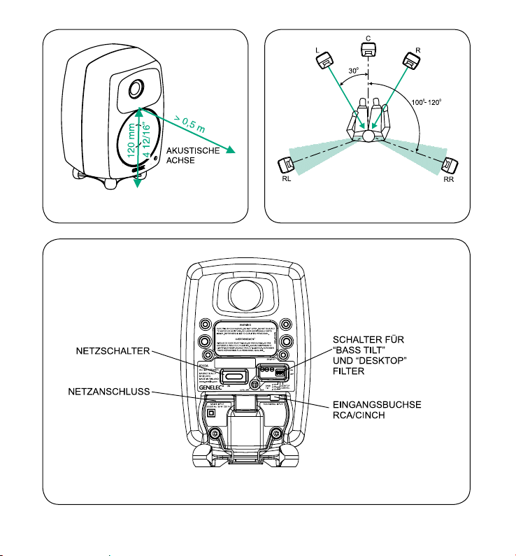
Abbildung 1. Lage der akustischen Achse
Abbildung 3. Anordnung der Anschlüsse und Einstellmöglichkeiten auf der Rückseite des 6010A-Gehäuses
Abbildung 2. Korrekte Ausrichtung der Laut-
sprecher eines 5-Kanal-Systems

Deutsch 9
Tabelle 1: Filtereinstellungsvorschläge für unterschiedliches akustisches Umfeld
Lautsprecherposition Desktop-Filter Bass Tilt-Filter
Reflexionsfreier Raum OFF OFF
Freistehend in gedämpftem Raum OFF OFF
Freistehend in halligem Raum OFF -2 dB
Wandnahe Positionierung OFF -6 dB
Im Nahfeld auf einer reflektierenden Fläche ON (-4 dB @ 200 Hz) -2 dB
In einer Ecke oder eingebaut in ein Möbelstück OFF -6 dB
Anschlüsse
Verbinden Sie den Lautsprecher und Steckdose mit
dem mitgelieferten Netzkabel. Vergewissern Sie sich
vor dem Anschließen, dass Lautsprecher und Sig-
nalquelle ausgeschaltet sind.
Der 6010A verfügt über einen unsymmetrischen
RCA-Audioeingang mit einer Eingangsimpedanz
von 10 kOhm. Die mitgelieferten Audiokabel er-
lauben den Anschluss von Quellen mit 3,5 mm
Klinkenbuchse oder RCA-Buchsen. Geeignete
Audioquellen sind beispielsweise Vorverstärker,
Computersoundkarten, portable Audioplayer und
Surround-Receiver mit „PRE OUT“-Anschlüssen.
Als aktiver Lautsprecher verfügt der 6010A über
eingebaute Endstufen. Es sind deshalb keine wei-
teren Leistungsverstärker notwendig. Der 6010A
darf keinesfalls mit dem Lautsprecherausgang von
Endstufen, Vollverstärkern oder Receivern verbun-
den werden.
Sind alle Verbindungen hergestellt, kann der
Lautsprecher eingeschaltet werden.
Einstellmöglichkeiten
Die Anpassung der Eingangsempfindlichkeit des
6010A an die Signalquelle kann mit Hilfe eines
Schraubendrehers an dem „LEVEL“-Regler auf der
Gehäuserückseite vorgenommen werden.
Der Frequenzgang des GENELEC 6010A lässt
sich zur Anpassung an die akustische Umgebung
mit den DIP-Schaltern an der Gehäuserückseite
beeinflussen. Die Filterfunktionen sind „Bass Tilt“
und „Desktop Control“. Die Tabelle 1 zeigt typische
Einstellungen für unterschiedliche Positionen im
Raum. Abbildung 4 zeigt die Wirkung der Einstel-
lungen im reflexionsfreien Raum. Ab Werk sind alle
Schalter in der Position „OFF“, die einen ebenen
Frequenzgang in reflexionsarmen Räumen ergibt.
Diese Einstellung ist ein guter Ausgangspunkt für
Optimierungen. Die beste Balance der Frequenzbe-
reiche findet sich bei Messung oder Hörtest durch
versuchsweises Aktivieren der verschiedenen Ein-
stellkombinationen.
Bass Tilt
Das „Bass-Tilt“-Filter erlaubt eine Abschwächung
der Basswiedergabe in drei Stufen. Diese wird
üblicherweise notwendig, wenn der Lautsprecher
nahe einer Wand oder einer anderen raumbe-
grenzenden Fläche aufgestellt wird. Die Absen-
kungsstufen sind -2 dB (Schalter 1 auf „ON“), -4
dB (Schalter 2 auf „ON“) und -6 dB (beide Schalter
auf „ON“).

10 Deutsch
Desktop Control
Das „Desktop“-Filter (Schalter 3) aktiviert eine 4 dB-
Absenkung der Bassfrequenzen um 200Hz. Diese
Filter eignet sich zur Kompensation von Anhebungen,
die durch die Nähe einer horizontalen Fläche (bei-
spielsweise einer Tischplatte) verursacht werden.
Montage
Der 6010A bietet mehrere Befestigungsmöglichkei-
ten: Der Iso-Pod™ (Isolation Positioner/Decoupler™)
ermöglicht die Neigung des Lautsprechers, um die
akustische Achse korrekt auszurichten. Der mitge-
lieferte Wandhalter erlaubt die Wandaufhängung in
zwei vertikalen Winkeln. Auf der Rückseite befindet
sich ein nach unten gerichtetes 3/8“-Gewinde, das
zu Standard-Mikrofonstativen und zu weiteren Zu-
behörartikeln passt. Ebenfalls auf der Rückseite an-
geordnet sind drei Paar Gewindebohrungen, die zu
Halterungen von Omnimount®, VESA und SANUS
passen. Eine vollständige Übersicht der verfügbaren
Optionen ist im „Accessories-Catalogue“ auf www.
genelec.com oder beim Genelec-Händler erhältlich.
Instandhaltung
Innerhalb des 6010A befinden sich keine Bauteile,
die vom Anwender gewartet werden können. Eine
Instandsetzung darf nur von qualifiziertem Fachper-
sonal ausgeführt werden.
Sicherheitsvorschriften
Der 6010A ist entsprechend internationalen Sicher-
heits-Standards konstruiert. Für einen sicheren Be-
trieb müssen die folgenden Warnhinweise beachtet
werden:
Instandsetzungen und Einstellungen dürfen nur•
von qualifiziertem Fachpersonal ausgeführt
werden. Das Gehäuse darf nicht geöffnet
werden.
Der 6010A darf nicht Wasser oder•
Verschmutzung ausgesetzt werden. Mit
Flüssigkeit gefüllte Behältnisse wie Vasen
sollen nicht nahe dem 6010A aufgestellt
werden.
Dieser Lautsprecher kann Pegel von über 85 dB•
erzeugen, die bleibende Hörschäden
verursachen können.
Die ungehinderte Luftbewegung an der•
Gehäuserückseite ist für die Kühlung notwendig.
Deshalb darf Luftbewegung in der Umgebung
des Gehäuses nicht eingeschränkt werden.
Beachten Sie, dass die Verstärkerelektonik•
erst dann vollständig von der Stromversorgung
getrennt ist, wenn das Stromversorgungskabel
aus Steckdose oder Lautsprecher entfernt
wurde.
Garantie
Für dieses Produkt wird eine zweijährige Garantie
auf Material- und Produktionsfehler gewährt. Wen-
den Sie sich an Ihren Lieferanten bezüglich der Lie-
fer- und Garantiebedingungen.
EG KONFORMITÄTSERKLÄRUNG
This is to certify that the Genelec Monitoring System
6010A conforms to the following standards:
Safety: EN 60065: 2002 + A1:2006 / IEC 60065:2001
7th Edition + A1: 2005
EMC: EN 55020 A2: 2008
EN 55013: (2001)+ A1 : 2003 + A2: 2009
EN 61000-3-2: 2006
EN 61000-3-3 A2: 2005
The product herewith complies with the requirements
of The Low Voltage Directive 2006/95/EC and EMC
Directive 2004/108/EC
Signed:
Ilpo Martikainen
Chairman of the Board
12-January-2009
Deutsch 11
Abbildung 5. Die obe-
re Kurvenschar zeigt
die horizontale Ab-
strahlcharakteristik des
6010A gemessen in
einem Meter Abstand.
Die untere Kurve zeigt
das Bündelungsmaß.
Abbildung 4. Das Dia-
gramm zeigt die Aus-
wirkung der Filter “Bass
Tilt” und “Desktop” auf
den Frequenzgang des
6010A.
12 Deutsch
TECHNISCHE DATEN
Lower cut-off frequency, –3 dB: < 73 Hz
Upper cut-off frequency, –3 dB: >21 kHz
Free field frequency response (± 2.5 dB): 74 Hz–18 kHz
Max. short term sine wave acoustic output
on axis in half space, averaged from
100 Hz to 3 kHz
@ 1 m
@ 0.5 m
>93 dB SPL
>99 dB SPL
Maximum long term RMS acoustic output
in same conditions with IEC weighted
noise (limited by driver unit protection
circuit) @ 1 m:
>91 dB SPL
Maximum peak acoustic output per pair
on top of console, @ 1 m distance with
music material:
>102 dB
Self generated noise level in free field @
1 m on axis (A-weighted):
<5 dB
Harmonic distortion at 85 dB SPL @
1 m on axis
Freq: 70…400 Hz
>400 Hz
< 3 %
< 0.5 %
Drivers:
Bass
Treble
76 mm (3”) cone
19 mm (3/4”)
metal dome
Weight: 1.4 kg (3.1 lb)
Dimensions:
Height including Iso-Pod™ table stand
Height without Iso-Pod™ table stand
Width
Depth
195 mm (711/16”)
181 mm (71/8”)
121 mm (43/4”)
114 mm (41/2”)
FREQUENZWEICHE UND FILTER
Input connector: Input: RCA female 10 kOhm: pin +,
sleeve -
Input level for 90 dB SPL output at 1 m: -6 dBu at
volume
control max
Level control range relative to max output: -12 dB
Desktop control operating range: 0 to –4 dB
@ 200 Hz
Crossover frequency, Bass/Treble: 3.0 kHz
Bass Tilt control operating range in –2 dB
steps:
0 to –6 dB
@ 100 Hz
The ‘CAL’ position is with all tone controls set to ‘off’ and the
input sensitivity control to maximum (fully clockwise)
.
VERSTÄRKER
Bass amplifier power with an 8 Ohm load: 12 W
Treble amplifier power with an 8 Ohm load: 12 W
Long term output power is limited by driver
unit protection circuitry
Amplifier system distortion at nominal output
THD+N:
<0.08 %
Mains voltage: 100, 120,
220 or
230 V
Voltage operating range: ±10 %
Power consumption
Idle
Full output
5 VA
35 VA
.

Français 13
6010A
Manuel d’utilisation
Description générale
Le Genelec 6010A est un haut-parleur actif à deux-
voies extrêmement compact conçu pour le home
cinéma et les applications multimédia profession-
nelles. En tant qu’ haut-parleur actif, il contient les
transducteurs, les amplificateurs, les filtres sépara-
teurs actifs et les circuits de protection. Le caisson
MDEMC (Minimum Diffraction EnclosureMC) du haut-
parleur est fait d’aluminium moulé sous pression
et est conçu pour réduire la diffraction aux arêtes.
Combiné au guide d’onde à directivité contrôlée
DCWMC (Directivity Control WaveguideMC), ce design
procure un excellent équilibre tonal même dans des
environnements acoustiques difficiles. Si néces-
saire, il est possible d’étendre la bande passante
du 6010A vers le bas en ajoutant un caisson grave
Genelec 5040A.
Contenu de l’emballage
Chaque 6010A est livré avec un support mural, un
cordon d’alimentation secteur, un câble avec fiche
3.5 mm à 2 fiches RCA, un câble signal à fiches
RCA – RCA, ce manuel d’utilisation et un guide de
configuration rapide. Après l’avoir déballé, placer le
haut-parleur à la position d’écoute désirée.
Considérations lors de
l’installation
Positionner les haut-parleurs correctement
Toujours placer les haut-parleurs de façon à ce
que leurs axes acoustiques (voir illustrations 1 &
2) convergent à hauteur d’oreilles vers la position
d’écoute. Seul le positionnement vertical est recom-
mandé, puisqu’il minimise les problèmes d’annula-
tions acoustiques dans la plage du séparateur de
fréquences.
Maintenir la symétrie
S’assurer que les haut-parleurs soient placés symé-
triquement par rapport à l’axe de la pièce, et qu’ils
soient équidistants de la position d’écoute. Si possi-
ble, installer le système de façon à ce que la position
d’écoute soit dans l’axe médian de la pièce et que
les haut-parleurs soient équidistants de cet axe.
Minimiser les réflexions
Les réflexions acoustiques d’objets proches des
haut-parleurs, tel que bureaux, meubles, écrans
d’ordinateur, etc peuvent estomper, colorer et
brouiller l’image sonore. Ces réflexions peuvent être
minimisées en plaçant les haut-parleurs loin de ces
surfaces réfléchissantes.
Dégagement minimal
On doit prévoir un espace suffisant pour le refroi-
dissement de l’amplificateur et pour le bon fonction-
nement de l’évent quand le haut-parleur est installé
dans un espace restreint tel un meuble ou une struc-
ture murale. Il faut toujours laisser autour du haut-
parleur un dégagement qui donne sur la position
d‘écoute. Un espace minimal de 2.5 centimètres (1
pouces) doit être laissé derrière, au-dessus, et de
chaque côté du haut-parleur. L’espace adjacent à
l’amplificateur doit être soit ventilé, soit de dimen-
sions suffisantes pour dissiper la chaleur de façon
à ce que la température ambiante n’excède pas 35
degrés Celsius (95°F).
Haut-parleur Actif
14 Français
Illustration 1. Position de l’axe acoustique
Illustration 3. Contrôles et disposition des connecteurs sur la face arrière de la 6010A
Illustration 2. Positionnement correct des haut-
parleurs pour un système multicanal à 5 canaux

Français 15
Tableau 1: Recommandation sur les réglages de tonalité dans différents environnements acoustiques
Connexion
Branchez le haut-parleur au secteur au moyen du
cordon d’alimentation fournit. Assurez-vous d’abord
que les haut-parleurs ainsi que les sources audio
soient éteintes.
Le 6010A possède une entrée audio RCA asy-
métrique de 10 kOhm. Les câbles de signal four-
nis avec le haut-parleur permettent une connexion
audio avec des sources ayant soit des fiches 3.5
mm ou des fiches RCA. Les diverses sources audio
peuvent être des préamplificateurs, des cartes son,
des lecteurs audio portables, les sorties ‘PRE OUT’
d’un récepteur home cinéma, etc.
En tant que haut-parleur actif, le 6010A contient
ses propres amplificateurs, et donc aucun amplifi-
cateur séparé n’est nécessaire. Ne jamais connec-
ter le 6010A aux bornes de sortie ‘haut-parleurs’
d’un amplificateur de puissance ou d’un amplifica-
teur AV intégré. Une fois les connexions faites, on
peut allumer les haut-parleurs.
Commandes
La sensibilité de l’entrée audio du 6010A peut être
ajustée au niveau de sortie de la source audio en
tournant la commande ‘LEVEL’ sur le panneau ar-
rière du haut-parleur avec un tournevis.
La réponse en fréquence du Genelec 6010A
peut s’accorder à l’environnement acoustique en
ajustant les commandes de tonalité sur l’arrière du
haut-parleur. Les commandes sont ‘Bass Tilt’, et
‘Desktop Control’. Le tableau 1 montre des exem-
ples d’ajustements typiques dans différentes situa-
tions. L’illustration 4 montre l’effet des commandes
sur la réponse en chambre anéchoïque. Les régla-
ges d’usine pour toutes les commandes de tona-
lité sont la position ‘OFF’ qui fournit une réponse
plane en chambre anéchoïque. On devrait toujours
commencer les ajustements avec tous les commu-
tateurs en position OFF. Mesurez ou écoutez sys-
tématiquement les différentes combinaisons pour
trouver le meilleur équilibre tonal.
Commande Bass Tilt
Le circuit Bass Tilt procure trois niveaux d’atté-
nuation pour la réponse en basses fréquences du
haut-parleur, généralement nécessaire lorsque ce-
lui-ci est placé près d’un mur ou autres parois. Les
niveaux d’atténuation sont -2 dB (commutateur 1
‘ON’), -4 dB (commutateur 2 ‘ON’), -6 dB (les deux
commutateurs ‘ON’).
Commande Desktop
La commande des basses fréquences “Desktop”
(commande 3) atténue les graves de 4 dB autour
Emplacement de l’enceinte Desktop Bass Tilt
Réponse plane anéchoïque OFF OFF
En champ libre dans une pièce absorbante OFF OFF
En champ libre dans une pièce réverbérante OFF -2 dB
Proche d’une paroi OFF -6 dB
Écoute rapprochée sur une surface réfléchissante ON (-4 dB @ 200 Hz) -2 dB
Dans un coin ou un meuble OFF -6 dB
Other manuals for 6010A
4
Table of contents
Languages:
Other Genelec Speakers System manuals

Genelec
Genelec S30D User manual

Genelec
Genelec 1032A User manual

Genelec
Genelec 1029A User manual

Genelec
Genelec 1032A User manual

Genelec
Genelec 8010 User manual

Genelec
Genelec SE User manual

Genelec
Genelec DSP 8260A User manual

Genelec
Genelec 1238AC User manual

Genelec
Genelec GLM 4 User manual

Genelec
Genelec AIC25 User manual

Genelec
Genelec PowerPak User manual

Genelec
Genelec PowerPak 8030A User manual

Genelec
Genelec 8030C User manual

Genelec
Genelec GLM 4 User manual

Genelec
Genelec AIW25 User manual

Genelec
Genelec 8320A User manual

Genelec
Genelec 8030 CP User manual

Genelec
Genelec AIW26 User manual

Genelec
Genelec S30-1038 User manual

Genelec
Genelec AIW26 User manual


