Genelec 1032A User manual

Genelec 1032A
Monitoring Speaker
Operating Manual
1032A
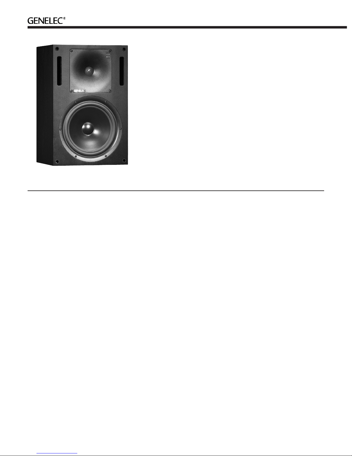
The bi-amplified GENELEC 1032A is a two
way active monitoring speaker de signed
for high output, low coloration and broad
bandwidth. It is based on the famous 1031A
near field monitor but offers extended low
frequency output with an increased maxi-
mum SPL.
Due to its compact size, integrated con-
struction, excellent dispersion and precise
stereo imaging this speaker system is ideal
for Near Field monitoring, mobile vans,
broadcast and TV control rooms and home
studios. Designed as an active speaker, this
unit contains drivers, power am pli fi ers, active
crossover filtering and protection circuitry.
The DCW™ Technology used provides
excellent frequency balance even in difficult
acoustic environments.
Drivers
The low frequencies are reproduced by a 10"
(250 mm) bass driver loaded in a 24 liters
vented cabinet. The -3dB point lies at 40 Hz
and the low frequency response extends
down to 36 Hz (-6dB).
The high frequency driver is a 1" (25 mm)
metal dome with pure piston behavior up to
23 kHz. The uniform dispersion control is
achieved with the rev o lu tion ary DCW Tech-
nol o gy pioneered by Genelec. The DCW also
provides perfect phase and delay uniformity
at the crossover frequency.
Both drivers are magnetically shielded.
Crossover
The active crossover network consists of
two parallel bandpass filters. Acoustically
the filters are complementary and the slopes
are 24 dB/octave. The crossover frequency
is set to 1,8 kHz. Using the active crossover
controls ('treble tilt', 'bass tilt' and 'bass roll-
off') this speaker to be exactly matched to
any room environment.
Amplifiers
The amplifier unit is mounted to the rear of
the speaker enclosure on quick release vibra-
tion isolators, to ensure rattle free operation
and long term reliability. The bass and treble
amplifier produce respectively 180 W and 120
W of short term power. The fast, low distor-
tion amplifiers are capable of driving a stereo
system to peak output levels in excess of 124
dB SPL at 1 m. The unit incorporates a special
protection circuitry for driver overload protec-
tion and amplifier thermal overload protection.
Variable input sensitivity allows for accurate
level matching to the console output section.
Installation
Each 1032A monitor is supplied with a
mains cable and an operating manual.
After unpacking, place the speaker so that
its acoustical axis (see figure 2) is aimed
towards the listening position. Do not place
the speaker in a horizontal position as this
may cause acoustical cancellation problems
around the crossover frequency.
Sufficient cooling for the amplifier must
be ensured if the speaker is installed in a
restricted space such as a cabinet or inte-
grated into a wall structure. The minimum
clearance for the amplifier is 10 centimeters
(4") to any object. The space adjacent to the
amplifier must either be ventilated or suf-
ficiently large to dissipate heat so that the
ambient temperature does not rise above 35
degrees Celsius (95°F).
Before connecting up, ensure that the
mains switch is off (see figure 1). Check
that the mains voltage selector is correctly
set (Models sold in Europe have a fixed 230
V setting). Audio input is via a 10 kOhm bal-
anced XLR connector, but unbalanced leads
may be used as long as pin 3 is grounded
to pin 1 of the XLR (see figure 3). Once the
connection has been made, the speakers are
ready to be switched on.
Genelec 1032A Monitoring Speaker
System
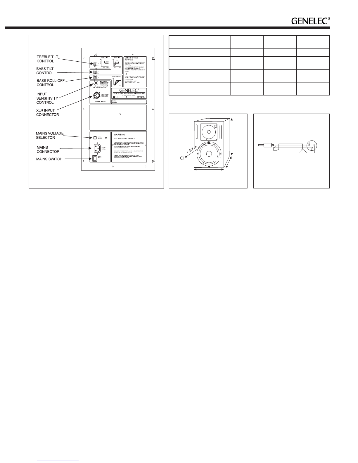
Setting the input sensitivity
The input sensitivity of each speaker can be
adjusted to match the mixing console output
level or other source by using the input sensi-
tivity con trol on the rear panel (see figure 1).
A small screwdriver is needed for the adjust-
ment. The manufacturer default setting for
this control is -6 dBu (fully clockwise) which
gives SPL of 100 dB @1m at -6 dBu input
level. Note that to get the full output level
of 113 dB SPL, an input level of +7 dBu is
needed at this setting.
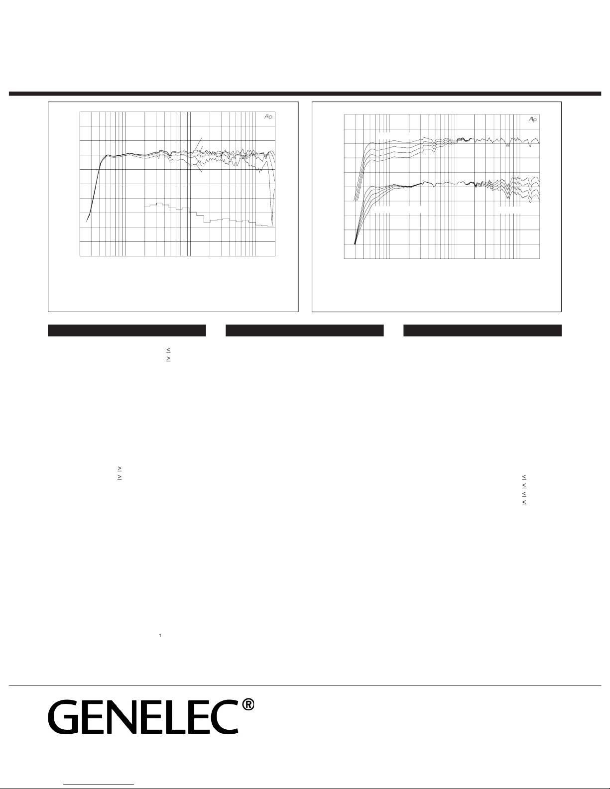
Setting tone controls
The response of the system may have to be
adjusted to match the acoustic environment.
The adjustment is done by setting the three
tone control switch groups ‘treble tilt’, ‘bass
tilt’ and ‘bass roll-off’ on the rear panel. The
factory settings for these controls are ‘All Off’
to give a flat anechoic response. See Table 1
for suggested tone control settings. Figure 5
shows the effect of the controls on the ane-
choic response. Always start adjustment by
setting all switches to ‘OFF’ position. Then set
only one switch to the ‘ON’ position to select
the response curve needed. If more than one
switch is set to ‘ON’ (within one switch group)
the attenuation value is not accurate.
Console top mounting
If the 1032A’s are used for for near field
monitoring, avoid mounting the speakers on
the meter bridge of the console. Instead posi-
tion them slightly behind the console by using
floor stands or wall mounts. This prevents the
the first reflections from the console surface
from coloring the direct sound.
Maintenance
No user serviceable parts are to be found
within the amplifier unit. Any maintenance
or repair of the 1032A unit should only be
undertaken by qualified service personnel.
Safety considerations
Although the 1032A has been designed
in accordance with international safety
standards, to ensure safe operation and to
maintain the instrument under safe operating
conditions, the following warnings and cau-
tions must be observed:
1. Servicing and adjustment must only
be performed by qualified service
personnel. The amplifier’s rear panel must
not be opened.
2. Do not use this product with an
unearthed mains cable as this may lead to
personal injury.
3. To prevent fire or electric shock, do not
expose the unit to water or moisture. Do
not place any objects filled with liquid,
such as vases on the speaker or near it.
4. Note that the amplifier is not
completely disconnected from the AC
mains service unless the mains power cord
is removed from the amplifier or the mains
outlet.
WARNING!
This equipment is capable of producing sound
pressure levels in excess of 85 dB, which
may cause permanent hearing damage.
Accessories
Order code
Flightcase
1032-401
Protective grille
1032-409
Wall mount
1032-404-V/H*
Floor stand
1032-405-V/H*
*State the desired speaker orientation
V=vertical or H=horizontal when ordering
these accessories.
Guarantee
This product is supplied with one year guaran-
tee against manufacturing faults or defects that
might alter the performance of the unit. Refer
to supplier for full sales and guarantee terms.
Figure 1. Amplifier panel layout of the 1032A
Figure 2. Location of the acoustic axis
Speaker Mounting
Position
Treble tilt
Bass tilt
Bass roll-off
Flat anechoic response
None
None
None
Free standing in a
damped room
None
-2 dB
None
Free standing in a
reverberant room
None
-4 dB
-2 dB
Near field or console
bridge
None
-4 dB
-4 dB
Table 1. Suggested tone control settings in some typical situations
Figure 3. RCA to XLR cable
Cable
Screen
RCA
(Source)
XLR
(Speaker)
290 mm
495 mm
320 mm
290 mm
1032A Operating Manual
Genelec Document D1032AR001 Copyright Genelec Oy 3.2003. All data subject to change without prior notice
www.genelec.com
AMPLIFIER SECTIONCROSSOVER SECTION
SYSTEM SPECIFICATIONS
Lower cut-off frequency, -3 dB:
<
40 Hz
Upper cut-off frequency, -3 dB:
>
22 kHz
Free field frequency response of system:
42 Hz - 21 kHz (±2.5 dB)
Maximum short term sine wave acoustic output on
axis in half space, av er aged from 100 Hz to 3 kHz:
@ 1m
> 113 dB SPL
@ 0.5m
> 119 dB SPL
Maximum long term RMS acoustic output in same
conditions with IEC weighted noise (limited by
driver unit pro tec tion cir cuit):
@ 1m
>
103 dB SPL
@ 0.5m
>
109 dB SPL
Maximum peak acoustic output per pair above
console bridge, @ 1 m from the engineer with
music ma te ri al:
> 124 dB
Self generated noise level in free field @ 1m
on axis:
< 10 dB (A-weighted)
Harmonic distortion at 90 dB SPL @ 1m on axis:
Freq:
50...100 Hz
< 1%
> 100 Hz
< 0.5%
Drivers:
Bass 10" (250 mm) cone
Treble 1" (25 mm) metal dome
Both drivers are magnetically shielded.
Weight:
21,7 kg (48 Ib.)
Dimensions:
Height
495 mm (19
1
/
2
")
Width
320 mm (12
5
/
8
")
Depth
290 mm (11
7
/
16
")
Bass amplifier short term output power with a
4 Ohm load:
180 W
Treble amplifier short term output power with an
8 Ohm load:
120 W
Long term output power is limited by driver unit
protection circuitry.
Slew rate
80V/µs
Amplifier system distortion at
nominal out put:
THD
<
0.05%
SMPTE-IM
<
0.05%
CCIF-IM
<
0.05%
DIM 100
<
0.05%
Signal to Noise ratio, referred to full out put:
Bass
> 100 dB
Treble
> 100 dB
Mains voltage:
230, 100/200 or 115/230V
according to region
Voltage operating range:
±10%
Power consumption:
Idle
20 VA
Full output
200 VA
Input connector XLR female:
pin 1 gnd
pin 2 +
pin 3 -
Input impedance:
10 kOhm bal anced
Input level for 100 dB SPL output @ 1m:
variable from +6 to -6 dBu
Input level for maximum short term sine wave output
113 dB SPL @1m:
variable from +19 to +7 dBu
Subsonic filter below 40 Hz :
18 dB/octave
Ultrasonic filter above 25 kHz:
12 dB/octave
Crossover frequency, Bass/Treble:
1.8 kHz
Crossover acoustical slopes:
24 - 32 dB/octave
Treble tilt control operating range in 2 dB steps:
from +2 to -4 dB & MUTE
Bass roll-off control operating range in 2 dB steps:
from 0 to -8 dB @ 40 Hz
Bass tilt control operating range in 2 dB steps:
from 0 to -8 dB @ 80 Hz
& MUTE
The 'CAL' position is with all tone con trols set to 'off'
and the input sensitivity con trol to maximum (fully
clockwise).
International enquiries:
Genelec, Olvitie 5
FIN-74100, Iisalmi, Finland
Phone +358 17 83881
Fax +358 17 812 267
Email [email protected]
In the U.S. please contact:
Genelec, Inc., 7 Tech Circle
Natick, MA 01760, USA
Phone +1 508 652 0900
Fax +1 508 652 0909
Email [email protected]
In China please contact:
Genelec China Representative Office
Soho New Town, 88 Jianguo Road
D-1504, Chaoyang District
Beijing 100022, China
Phone +86 10 8580 2180
Fax
+86 10 8580 2181
AUDIO PRECISION 1032anec vs 02 FEB 93 18:51:59
60
65
70
75
80
85
90
80
85
90
95
LEVEL(dBr)
20 100 1k 10k 20k
FREQ(Hz)
BASS TILT
TREBLE TILT
BASS ROLL-OFF
AUDIO PRECISION 1032anec vs 02 FEB 93 18:56:42
80
85
90
95
100
LEVEL(dBr)
20 100 1k 10k 20k
FREQ(Hz)
0°
15°
30°
45°
65
70
75
80
85
90
95
Figure 4. The upper curve group shows the horizontal directivity
characteristics of the 1032A in vertical configuration measured at 1 m.
The lower curve is a 1/3 octave band power response, measured in an
IEC approved reverberation chamber.
Figure 5. The upper curve group shows the effect of the bass tilt
control on the free field response. The lower curves show the effect
of the treble tilt and bass roll-off controls.
Other manuals for 1032A
7
Other Genelec Speakers System manuals

Genelec
Genelec 6010A User manual

Genelec
Genelec 1238AC User manual

Genelec
Genelec PowerPak User manual

Genelec
Genelec AIC25 User manual

Genelec
Genelec aiw26b User manual

Genelec
Genelec 1029A User manual

Genelec
Genelec GLM 4 User manual

Genelec
Genelec GLM 4 User manual

Genelec
Genelec S30D User manual

Genelec
Genelec DSP 8260A User manual

Genelec
Genelec 8320A User manual

Genelec
Genelec SE User manual

Genelec
Genelec 1032A User manual

Genelec
Genelec 8010 User manual

Genelec
Genelec PowerPak 8030A User manual

Genelec
Genelec S30-1038 User manual

Genelec
Genelec 8030 CP User manual

Genelec
Genelec 8030C User manual

Genelec
Genelec AIW25 User manual

Genelec
Genelec AIW26 User manual


