Genelec 8381A User manual

Genelec 8381A
Smart Active Monitor
Operating Manual
8381A

8381A Quick Setup Guide
Needed tools
Inventory
Warnings
E
2 x
B
Torx 20
Do not use blades for opening plastic bags.
Caution! Heavy package. Lift carefully with the help of another person.
70
kg
!
Please only remove the protective foam in front of the drivers after
completely assembling the monitor unit.
2 x
D
5 m
C
0,5 m
A
0,25 m
F
12 x
M4x10
2 x
G
I
Kiitos. Thank you.
L
H
M
8 x
K
WARNING: This loudspeaker may cause traumatic and permanent
hearing damage. Before applying power, read the warnings in the
operating manual and the paragraphs about analogue and digital
input sensitivity.
A CAT45 cable
B Interconnection
cable
C CAT45 cable
D CAT45 cable
E Protective plate
F Bolt
G XLR
H Speakon
I Protective sleeve
J Mains cable
K Rubber feet for
ampliers
L Card
M 8381A Quick Setup
Guide
J
2 x

Unpacking and assembling
Remove the two large pieces of foam
padding.
3. Remove both ampliers and take them out
of their plastic bags.
4.
Remove screws from the box’s base and lift
the box’s top section away.
1. Remove accessory box, then cut incliner
wedges free and remove them.
2.
70
kg
!
Torx 20
(Optional) If tilting is needed, install incliner
wedge onto lower enclosure. Attach with
4 pcs M4x10 torx bolts.
6.
Remove plastic bag from the lower enclosure
and lift lower enclosure to nal location.
5.
70
kg
!Torx 20,
max. 1Nm
Fx 4

Carefully remove protective foam. Foam
has been secured with double-sided tape.
10.
Attach protective plates (E) using 8 pcs torx
bolts (F) in total. Do not overtighten.
9.
Torx 20,
max. 1Nm
Fx 8
E
E
Connect ampliers to inputs in bottom
enclosure using cables D and H. Match
amp 1 to input 1 and amp 2 to input 2.
Match serial numbers between ampliers
and enclosure inputs. (Optional) Sleeve (I)
may be used over cables D and H.
11. Use cables C, D, and G to connect
ampliers to each other, and J to the mains
power. Scan QR code to read detailed
explanation in 8381A Operating Manual
and GLM System Operating Manual.
12.
D H
I
C D
G J
Remove plastic bag from upper enclosure
and lift upper enclosure onto lower enclosure.
7. Insert cables A and B to connect upper and
lower enclosures. Carefully push cable into
space between enclosures.
8.
70
kg
!
B
A
Genelec Document BBAGE232 Copyright Genelec Oy 10.2023. All data subject to change.

Genelec 8381A Operating Manual
Introduction
Congratulations and thank you for choosing
Genelec!
Since 1978, Genelec has been guided
by a single idea – to make exceptional
active monitors that deliver neutral and
accurate sound in every kind of acoustical
environment. In Genelec’s quest for this
ultimate goal, our unrivalled commitment
to research and development has led us
to continuously develop innovative driver
technology, electronic circuitry, enclosure
designs and more. Our design philosophy
is based on sustainability and environmental
values, where industrial design serves the
acoustical performance of our products.
Your Genelec product has been designed
and manufactured with great care in our
factory, in Finland, using environmentally
efficient solutions to give you reliable
operation over many years.
Please take the time to read this manual.
Happy monitoring!
General Description
System Design
The Genelec 8381A Adaptive Point Source
Main Monitor is intended for free-standing
placement and is designed for precise stereo
imaging and neutral sound reproduction
in high sound pressure level applications
in medium to large control rooms. The
maximum SPL of the 8381A enables use
at most control room listening distances at
high linearity, delivering excellent audible
dynamic range. The system can be placed
directly on the oor when an acoustic axis
height equal to the typical seating height in
a studio is needed for natural stereo image
creation (1.2 m) and includes an inclining kit
to optimally aim the acoustic axis towards
the listening position when the monitors is
placed on a pedestal so that the acoustic
axis is located higher. A height extension
block is available as an option.
High Resolution
The system low frequency response extends
down to 20 Hz (-6 dB) and up to 35 kHz (-6
dB) for complete recorded audio content
playback capability and capacity for high
resolution output. The system is time
aligned for equal input-to-output delay at
all frequencies down to 200 Hz, ensuring
perfect transient waveform delity.
Point Source Architecture
The acoustically coaxial operating principle
– with the adaptive woofer technology –
enable precise reproduction integrating also
the very low frequencies in the sound image
excellently to the full audible frequency range
while minimising room-related inuence on
sound, improving the quality of the complete
system sound imaging. In the Adaptive
Point Source Continued Directivity design,
most frequencies of audio appear to come
from the same location and the directivity is
maintained across the frequency range.
Because the acoustic design of 8381A is
a Point Source down to bass frequencies,
the listening distance can be freely selected,
including very short listening distances. The
maximum listening distance is not limited
and is normally set by the maximum SPL
requirement at the listening location, giving
8381A great exibility.
Time-Domain Alignment
In addition to keeping the directivity and
source of audio constant, the 8381A monitor
also very carefully aligns all frequencies in time,
so that the input-to-output latency of 8381A
is constant over a wide range of frequencies,
and this improves the reproduction of the
pressure waveforms and imaging.
All loudspeakers naturally delay audio.
This delay progressively increases towards
low frequencies and when the bandwidth
Warning!
This loudspeaker may cause
traumatic and permanent hearing
damage. Read warnings in the
operating manual before applying
power. Ear protection should be
worn at all times when working in
the vicinity of a powered system.

Figure 1. Principles of maintaining directivity; high frequencies in the tweeter (left), coaxial midrange driver range (middle) and low
midrange (right).
Figure 2. Principles of maintaining directivity; low midrange (left) matches to the
directivity of the 15-in woofer (right).
gets narrower. This means that in a typical
loudspeaker, the input-to-output latency is
the smallest close to the highest frequency,
progressively increases towards the bass
frequencies, and close to the low corner
frequency where the loudspeaker output
starts reducing the input-to-output delay is
usually the highest.
Genelec monitors use digital signal
processing to align the input-to-output delay.
This is done by applying a very small amount
of delay to higher frequencies to line them up
with lower frequencies. 8381A monitor oers
two values for this line-up, ‘low latency’
and ‘extended phase linearity’. These can
be selected in the GLM software. The ‘low
latency’ mode applies the minimum amount
of additional delay at higher frequencies
and can keep the latency constant down to
about 500 Hz. The ‘extended phase linearity’
setting applies just a little bit more delay
at higher frequencies and keeps the delay
constant down to about 200 Hz. As the delay
has a relationship to the rate of changes of
the system phase response, these settings
also have the eect that the phase change
for audio down to these frequencies
remains very small, and all audio output is
in phase across the important mid and high
frequencies, and this results in very accurate
reproduction of the waveforms at the monitor
output and therefore excellent reproduction
of the details in audio transients.
High-SPL Coaxial
The coaxial driver is installed in a directivity
control waveguide (DCW). The coaxial driver
uses a high linearity compression tweeter
with a 13 mm (.5 in) throat diameter and a
5-in conical midrange driver forming a part
of the complete Genelec Directivity Control
Waveguide™ (DCW™) design. The system
directivity is set by the driver size (diameter)
and the directivity control eect of the DCW
and enclosure front.
Quad Midrange System
The top enclosure offers an acoustic
point source design the high SPL tweeter-
midrange coaxial driver in a DCW is
supplemented with four 127 mm (5 in) dome
drivers. Combined, their acoustic output
appears to locate on the same acoustic
axis with the coaxial driver, and the quad
Figure 3. Room-adaptive woofer
system adjusts directivity accord-
ing to room acoustics so that the
frequency response is neutral at the
listening position.

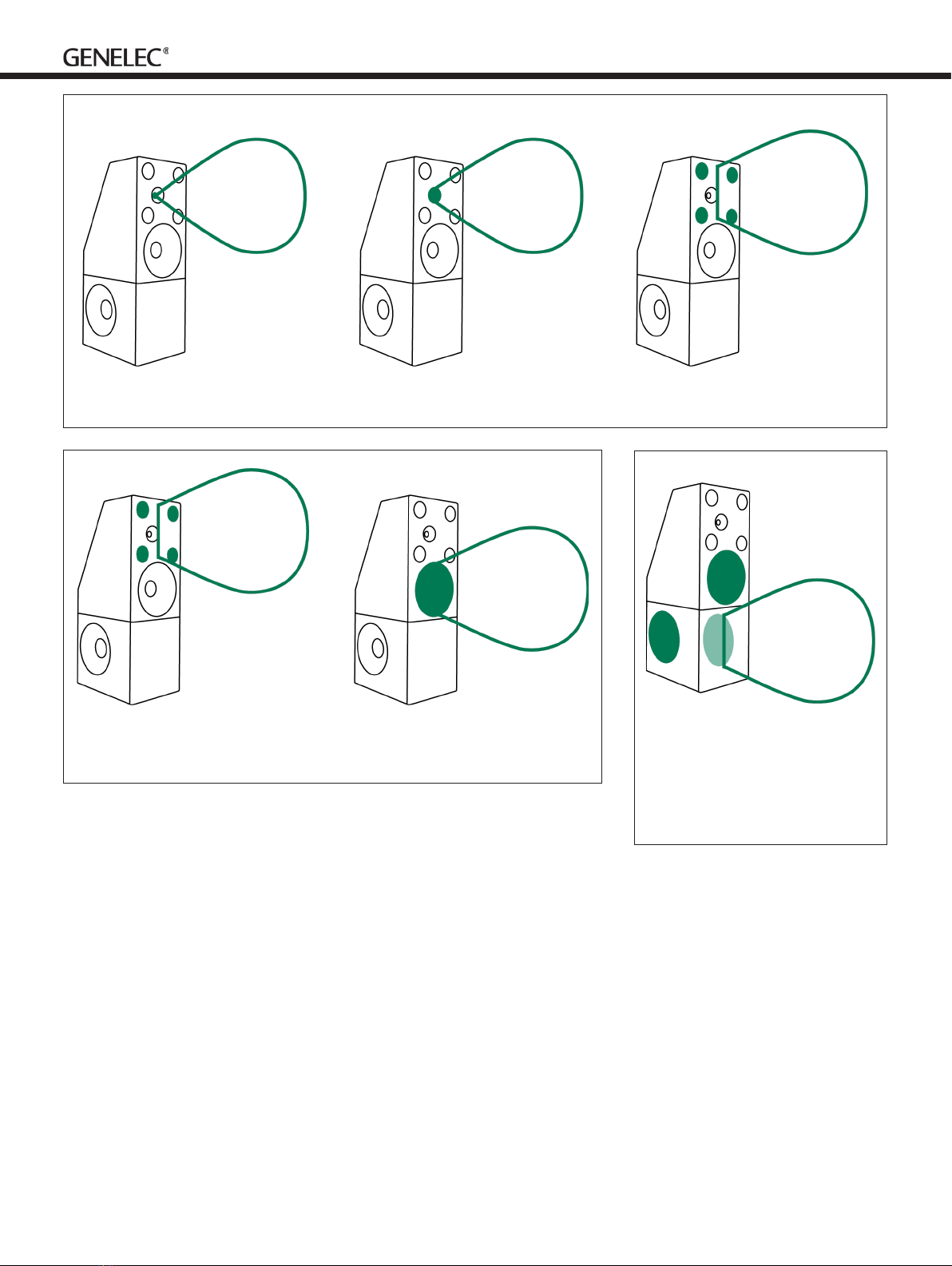
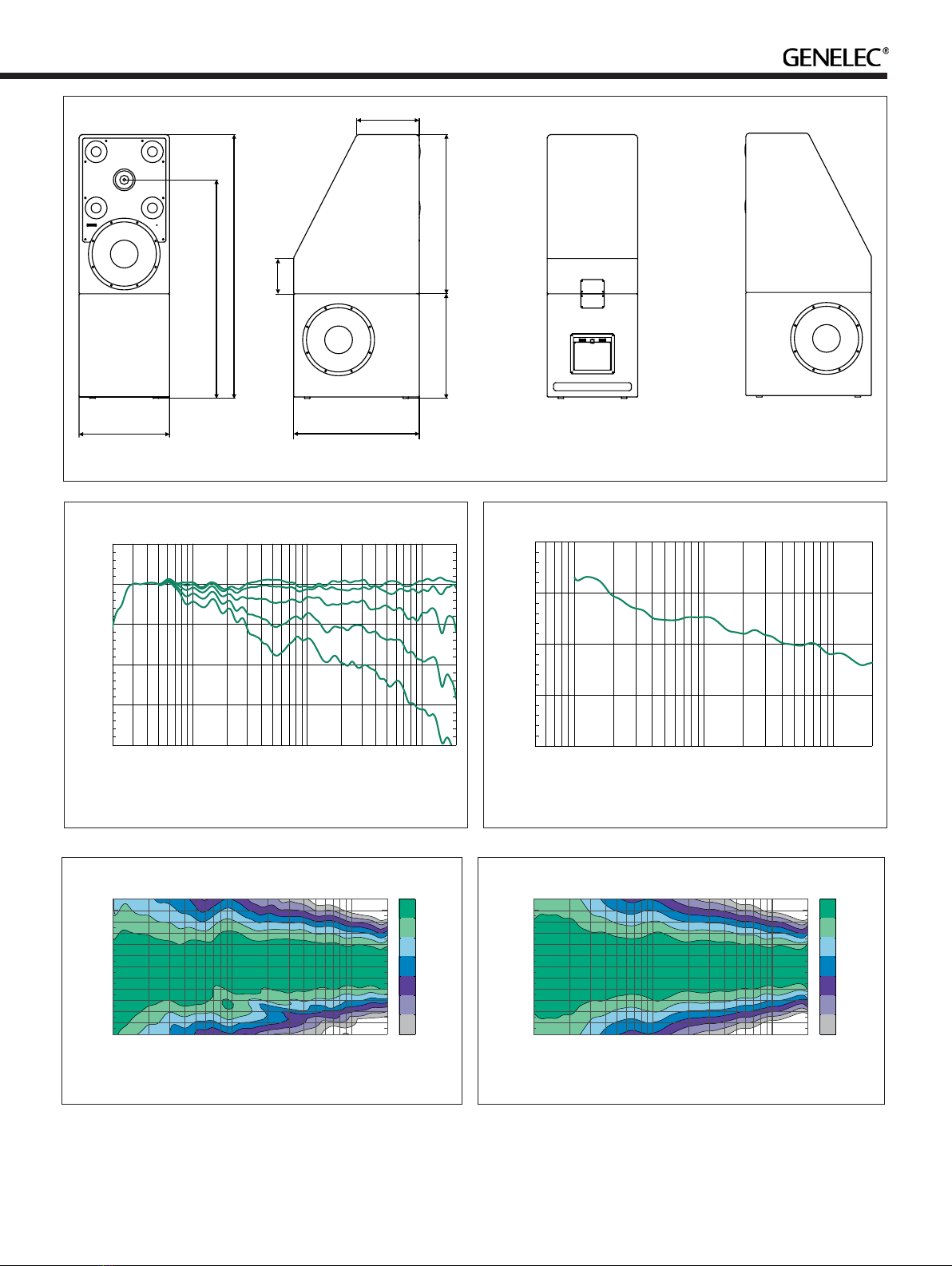
midrange system directivity matches with
the coaxial system and the 381 mm (15 in)
front woofer, maintaining directivity at upper
bass, midrange and to high frequencies. This
results in a well-controlled and predictable
sound character in all room acoustics and
produces detailed and precise acoustic
imaging for free-standing monitoring
loudspeaker arrangements.
Room Adaptive Woofer System
The woofer in the front of the top enclosure
and the two woofer transducers in the bottom
enclosure combine into a Complementary
Mode adaptive woofer system. The two
lowest crossover frequencies are adjustable
with the GLM software. The crossovers
from the quad midrange system to the front
woofer and from the front woofer to the
double low-woofer system can also be set
during system calibration with GLM.
Towards low frequencies, the bass
reproduction moves from to the front 381
mm (15 in) woofer to the bottom enclosure
housing two recoil-compensated 381 mm
(15 in) woofers in a bass reex enclosure –
with a port opening towards the back of the
enclosure.
The adjustable crossover frequencies
enable the complete bass reproduction to
be adapted depending on the loudspeaker
location and listening location. This
adaptation is done with the aid of the
Genelec Loudspeaker Manager, during the
system calibration, the bass output at the
listening location is calculated by GLM and
is optimised during the calibration process.
This ensures at low frequency output with
minimizing the problems related to room
resonances in the total system response.
This creates a high output bass reproduction
system with excellent precision.
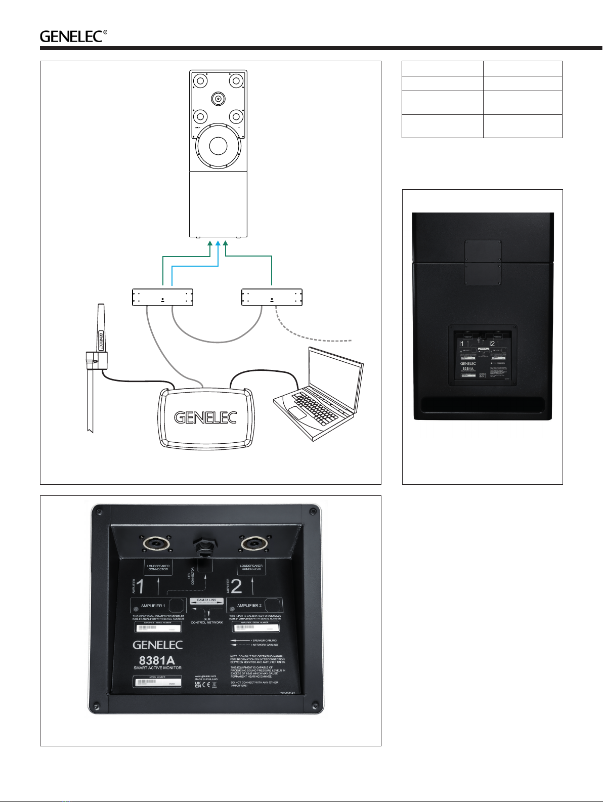
Amplifiers
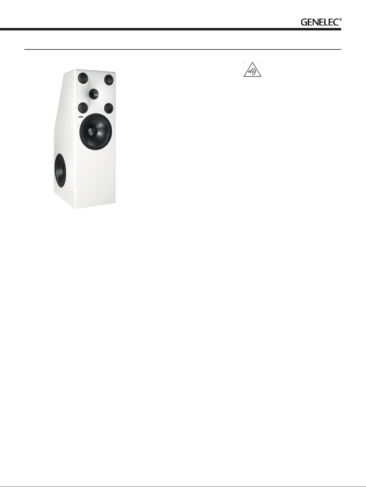
The 8381A system is a two-part design
comprising top and bottom enclosures
and two dedicated RAM-81 amplier units.
The amplier units are 19-in 3U high rack
mount enclosures, and each amplier unit is
factory calibrated to a unique enclosure and
contains a serial number that matches with
the enclosure input.
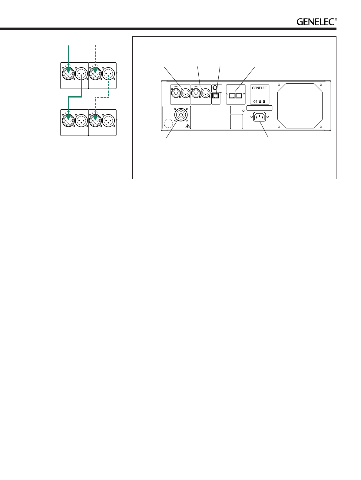
The power amplifiers in the RAM-81
produce 2600 W, 2400 W, and 926 W
short-term power, respectively, for the three
woofers, quad midranges, and coaxial driver
midrange and tweeter combined. The total
amplifier power is 5926 W. Both RAM-81
ampliers are needed to power all drivers
in the full 8381A system. The high power
capacity ensures wide dynamic range and
clean transient reproduction even for the
most demanding audio signals.
Signal Processing
Digital signal processing in the RAM-81
amplifier unit is done with high precision
algorithms. Each RAM-81 is factory-
calibrated to a specic 8381A enclosure and
is adapted by GLM management software
for room acoustics to obtain neutral sound
character. The signal processing includes
driver and amplifier overload protection
and ISS power saving for the highest
eciency and long-term system reliability.
The room response compensations include
highly flexible parametric filters, level
alignment, acoustic delay compensation,
and low frequency output adaptation.
These allow accurate matching to all DAW
output sections and room acoustics in the
most demanding free-standing monitoring
loudspeaker installations.
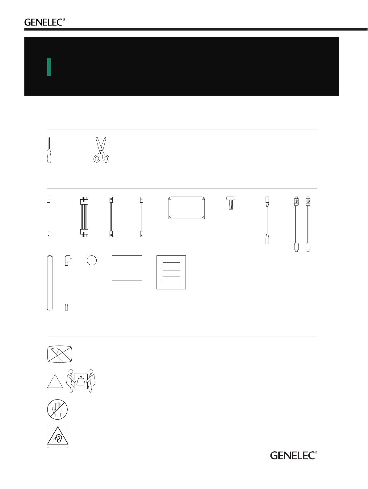
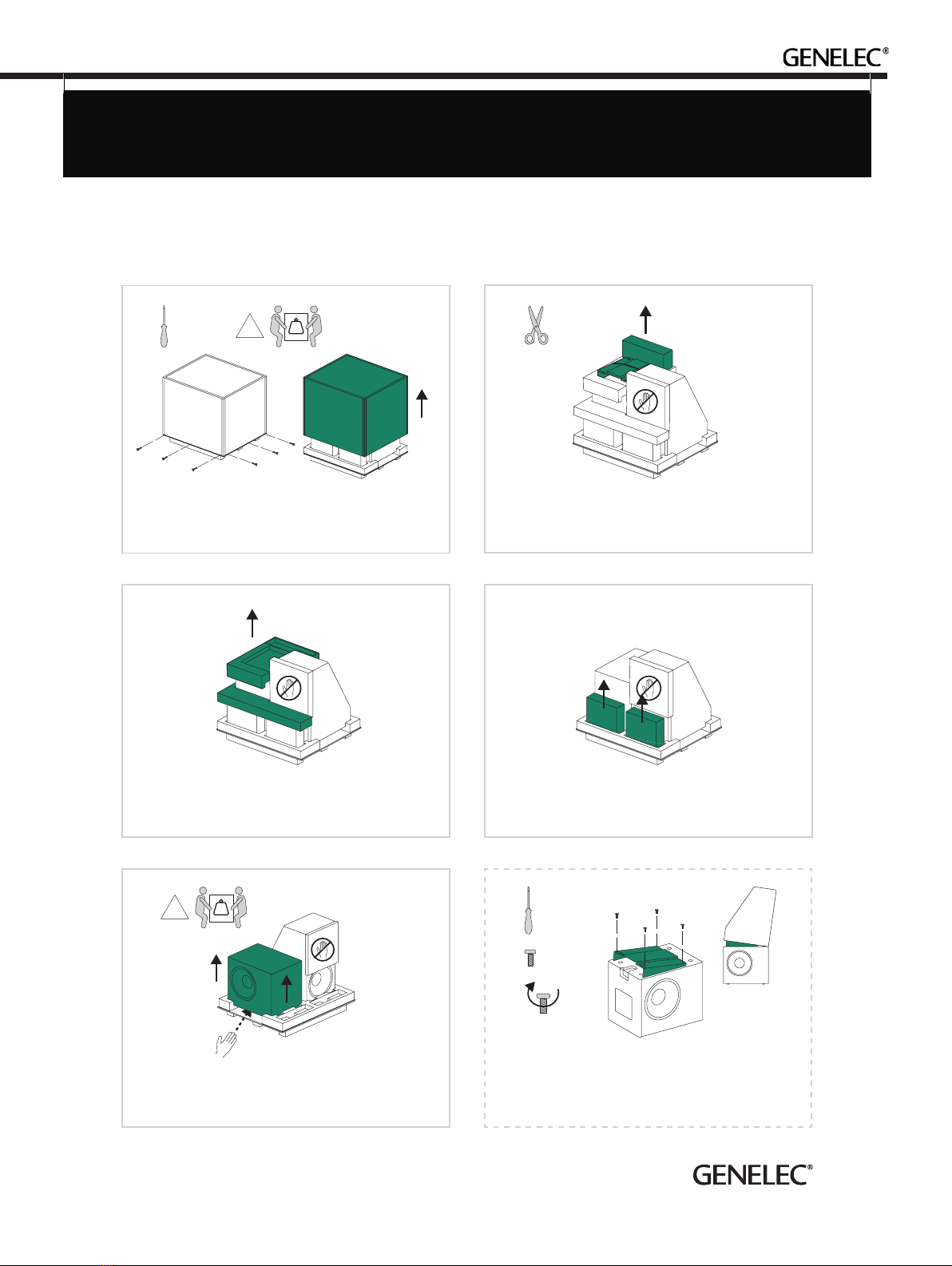
Accessory Kit
Each 8381A is delivered with the following
accessory kit:
• Two mains cables (for ampliers).
• For connecting the ampliers to the
enclosures: One cable sleeve to cover all
cables, two 8-pole 'Speakon' cables and
one RJ45 cable, each 5 m (20 ft).
• For interconnecting the two amplier
units: One RJ 45 cable, two XLR male-
to-female cables, each 0.5 m (1.5 ft).
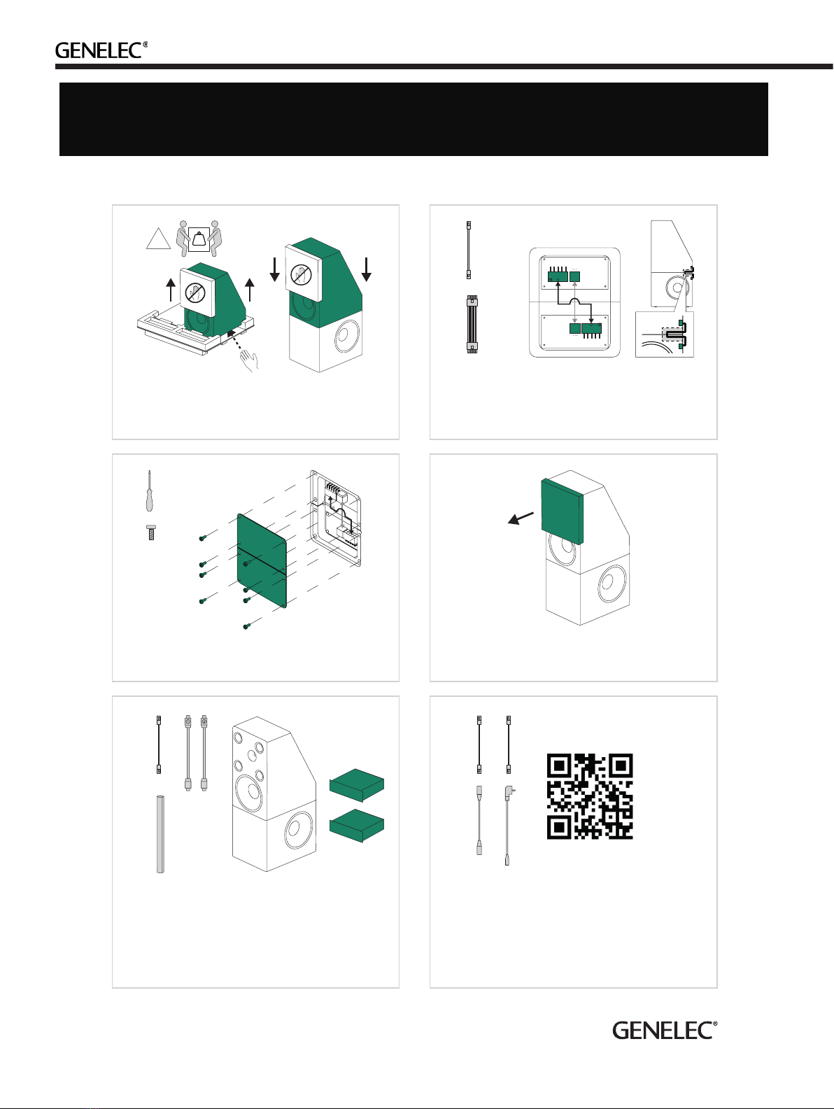
• For connecting bottom and top
enclosures: One at multipole cable 0.25
m (0.8 ft), one RJ45 cable 0.25 m (0.8 ft).
• Two sheet metal plates with screws for
covering the enclosure interconnection
areas in the top and bottom enclosures.
• Top enclosure incliner wedges, one 4
deg and one 8 deg (for downward angles
4 degrees and 8 degrees).
• Printed Quick Setup Guide
In addition, a Genelec Loudspeaker
Manager (GLM) kit will be provided with
each pair of 8381's. All except the incliner
wedges are required to complete the 8381A
monitor system setup. The incliner wedges
are optional and should be used when the
8381A is installed such that the coaxial
driver is higher than the listening level.
In addition to the accessories included
with the 8381A, a height extension block
8381A-480 is available separately. The
height extension block increases the height
of the acoustic axis of 8381A by 300 mm
(12 in). This height extension is suitable in
situations where the monitoring is also done
standing up or when the studio equipment
layout requires the acoustic axis of the
monitor to be high.
Installation Height and Axis
Optimisation
The system default acoustic axis height
optimally presents the sound image for a
seated listener, but 8381A axis height can
be optimised by placing the monitoring
system on a pedestal. High acoustic axis
placement can be useful when the furniture
in the room prevents lower axis height from
being used, to emulate traditional high main
monitor placement or to have more equal
presentation in a situation where the system
is frequently auditioned standing up.
The 8381A system comes with two incliner
wedge accessories to optimise the acoustic
axis vertical aiming. One wedge accessory
can be placed between the bottom enclosure
and the top enclosure. The top enclosure tilt-
down can be 4 or 8 degrees (see Figure 5).
This allows optimal vertical alignment towards
the listening location. Do not use both wedges
at the same time or use them "backwards" to
tilt the top enclosure upwards
.
Operating Environment
Mains Power, Voltage, Frequency and
Thermal Load
The 8381A monitoring system uses two
RAM-81 amplifier units, each built in
a standard 19-in 3U size rack-mount
enclosure. Connect the ampliers to mains
outlets with safety ground (protective earth)
terminal connections. The RAM-81 amplier
is compatible with a universal mains voltage
input from 100-240 VAC with a mains
frequencies 50-60 Hz, and always deliver full
power despite the mains voltage level. The
RAM-81 amplifiers contain turn-on surge
reduction and power factor compensation,
reducing the electrical system peak load.
Although the peak output power of the

ampliers is about 6 kW, the mains power
connection must be able to provide 2.2
kW of continuous power. The difference
between the mains input power and peak
output power is supplied by the amplier
power storage capacity.
When the 8381A is idle, the power
consumption is about 140 W. This is also
usually the thermal load of the 8381A as
the thermal load is caused by the amplier
unit idle power consumption while extended
playback at very high output level will
increase the thermal load.
The RAM-81 ampliers have a temperature
controlled forced air cooling, and the fan
rotation speed is normally very low and does
not cause audible noise. However, if thermal
load increases, the fan will run faster and
cause some noise. For critical application
and for maximum performance, Genelec
recommends that the RAM-81 amplier units
are remoted into a separate space, in an air-
conditioned equipment rack.
Operating and Storage Environment
The monitor enclosures and RAM-81
ampliers are designed for indoor use only.
The operating ambient temperature of the
monitoring system is 15-35 °C (50-95 °F)
and permissible non-condensing relative
humidity between 20-80 %.
If the product has been stored or
transported in cold and is then taken into
a warm room, the product must warm up
to ambient temperature inside unopened
packing for at least three hours before
opening the packing and connecting to the
mains power.
As the enclosures are made of MDF
medium fibre board, they should be
protected from water or other liquids
accumulating on the top of the enclosure
or other surfaces. Prolonged exposure to
liquids will aect the board.
Clearances Amplifier
A forced-air cooling system circulates air
into the amplier from behind, and air exits
through openings on the right side. Free
space around the amplier must be sucient
to ventilate accumulating heat.
Place the amplier so that at least 100
mm (4 in) free space is available behind the
amplier to allow for cable connections and
air circulation and the perforated side of the
amplier should be open in the rack to allow
air to ow – the rack sides must not block
the openings in the amplier.
If the amplier overheats, it shuts down
until a safe temperature is reached. When
the amplifier is placed in a constrained
environment, such as an equipment rack,
there should be sucient air conditioning
inside the constrained space to maintain the
ambient temperature below the maximum
value.
Clearances Enclosure
Space of at least 50 mm (2 in) should be left
behind and around the monitor enclosure
because the bass reex port in the lower
enclosure opens to the back and clearance
to the wall is needed to avoid reduction of
bass output or increase of distortion.
Ensure that the speaker cables can reach
the rear of the enclosure.
Mechanical Vibrations
If the flooring construction is light, the
monitor can be mounted on vibration
isolators to reduce mechanical resonances
and vibrations in the floor and other
structures. The mechanical resonant
frequency of the monitor on the vibration
mount should not be higher than 2–8 Hz for
eective vibration isolation.
Installation
See Quick Setup Guide on pages 2-4.
Delivery on Pallet
The Genelec 8381A Smart Active Monitor
is shipped in a plywood-covered pallet
containing two enclosures, two individually
calibrated RAM-81 amplier units, and an
accessory kit.
The monitor pallet is heavy; almost 200 kg
(440 lb). It should be moved carefully using
proper methods and a pallet truck.
The free opening in the door frame has
to be more than 1 m (39 3/8 in) to allow the
pallet to be taken into the room.
Before installing the system, check all
items for damage and omissions. If damage
is found, directly contact the dealer and
insurance agent. If there are any missing
components, contact your local dealer.
Opening and Accessing the
Components
The packing crate is closed with screws.
Place the create on the oor and remove the
screws at the bottom of the crate using the
correct screwdriver. Do not open at the top.
Once all screws at the bottom are
removed, lift the complete covering box (top
and sides) up and away as one unit. At least
two persons are needed for this because of
the size of the top.
Removing the complete covering box
gives easy access to all the parts.
Remove the inclining wedges and the
accessory box. Remove the ampliers.
Assembling at Installation Location
If the coaxial unit of the 8381A must be
higher than 1.2 m, place the necessary
height extension pedestal on the oor. The
necessary height extension must be supplied
separately. An optional 300 mm (12 in) height
extension block is available from Genelec.
The pedestal must be able to support the
full weight of the two enclosures, about 160
kg (350 lb). We recommend a mechanically
robust pedestal material and construction
to avoid any acoustic resonances in the
pedestal and to be able to support the full
weight of the monitor system.
Genelec recommends at least two
persons for lifting and moving the individual
loudspeaker enclosures. Please pay
attention to the weight of each enclosure
and note that hitting any objects while lifting
and moving the enclosure can cause visible
marks or even dents onto the enclosure
surface and painting nish.
First lift the bottom enclosure out and place
it to the nal installation location. At least two
persons are needed for this. To lift the unit,
hands must go under the unit. The cushioning
has openings to allows this. Note that the unit
is heavy, more than 70 kg (155 lb).
If necessary, place the inclining wedge
on the bottom unit at this time. When the
designed coaxial driver height is more than
1.2 m or if the listening position is much lower
than 1.2 m from the oor, install the correct
incliner wedge to direct the acoustic axis
towards the listening position (see Figure 5)
.
Attach the wedge to the bottom enclosure
with four M4x10 Torx bolts provided in the
accessories package.
Lift the top enclosure out and place it
on top of the bottom enclosure (or incliner
wedge, if used). At least two persons are
needed for this. To lift the unit, hands must
go under the unit. The cushioning has
openings to allows this. Note that the unit is

heavy, more than 70 kg (155 lb).
The top enclosure DCW area is covered
by a plastic protection sheet. Do not remove
this until the enclosure is fully assembled in
its intended location and do not apply any
pressure on it as this may damage the 5 in
midrange domes. Remove the protection
sheet attaching tapes carefully to avoid
marks in the paintwork. Store the protective
sheet for possible later use if the top
enclosure has to be moved.
Note: The top enclosure must be placed
on top of the bottom enclosure to get the
designed acoustic characteristics and
frequency response quality. Genelec does
not recommend the top enclosure to be
placed away from the bottom enclosure and
does not support such placements.
Warning: Do not apply pressure on the 5
in domes in the DCW area. Avoid touching
the domes. Structural changes in the domes
may aect the sound quality.
Placement and Aiming
The 8381A monitor is designed to be placed
free-standing on the oor. The monitor has
point source characteristics down to 200 Hz.
Because of this the listening distance can
be chosen quite freely – down to a listening
distance of around 1 m (3 ft). The automatic
calibration system with the adaptive woofer
system allows excellent performance in free-
standing positions, away from room walls.
These characteristics together allow the
monitor to be placed at the ideal loudspeaker
locations for monitoring in the room.
Acoustic Axis Definition
The monitor acoustic axis is at the centre of
the coaxial driver. This axis from the middle
of the coaxial driver should point at the
listener. This is also the measuring axis of
the system (see Figure 4).
Selecting the Installation Height
Consider the need of lifting up the 8381A if
you have high furniture such as the mixing
console, to give the mid and high frequency
drivers enough clearance over the tops of
the furniture. An optional 0.3 m (1 ft) pedestal
is available from Genelec for this.
Aiming the Acoustic Axis
The monitor should be aimed horizontally
and vertically toward the listener.
When the monitor is placed on the
floor, the acoustic axis height is 1.2 m.
When listening at the typical sitting height
(1.2 m), no vertical alignment is needed.
In applications where the monitoring is
frequently done standing up, axis direction
should be adjusted vertically to midway
between the standing and seated positions,
typically 1.5 m (5 ft from the oor), allowing
similar frequency response for standing and
seated listening positions.
Acoustic Axis Optimisation When
Monitor is Lifted
When the monitor is lifted on a pedestal,
the top enclosure can be tilted towards the
listener. For a typical seating height, this
normally means the top enclosure acoustic
axis is pointing slightly down. This can be
achieved by tilting the top enclosure slightly
forward using an incliner wedge, to achieve
either a 4 or 8 degree tilt-down angle. These
wedges are included with the 8381A. The
wedges are marked with the tilt angle.
Genelec does not recommend using any
other method for tilting the top enclosure as
the wedges are designed to create structural
rigidity and ensure that the enclosure stack
has maximum stability when tilted.
See Figure 5 for the acoustic axis height
at different distaces when using the tilt
wedges.
Connections
Enclosure to Enclosure Cabling
Locate the covering plates at the top of the
bottom enclosure and the bottom of the
top enclosure – these are included in the
Accessories Kit.
Locate and connect the 0.25 m (0.8 ft)
at cable and 0.25 m (0.8 ft) RJ45 cables
between the top and bottom enclosures.
These cables are provided in the Accessories
Kit.
After cables are in place, attach the
covering plates using the included screws.
1208 mm
(47 9/16 in)
Acoustical axis
Figure 4. Height of the acoustical
axis. Horizontally the axis is located
at the centreline of the enclosure
Acoustical axis
1140 mm
(44 7/8 in)
1071 mm
(42 1/8 in)
1001 mm
(39 3/8 in)
931 mm
(36 5/8 in)
1000 mm
(39 3/8 in)
2000 mm
(78 3/4 in)
3000 mm
(118 1/8 in)
4000 mm
(157 1/2 in)
Acoustical axis
1074 mm
(42 5/16 in)
934 mm
(36 3/4 in)
793 mm
(31 1/4 in)
652 mm
(25 11/16 in)
1000 mm
(39 3/8 in) 2000 mm
(78 3/4 in)
3000 mm
(118 1/8 in)
4000 mm
(157 1/2 in)
Figure 5. Height of the acoustical axis using the 4 deg (above) and 8 deg (below)
incliner wedges. Do not use the wedges to tilt the top enclosure upwards

Figure 6. GLM control network cabling, speaker cables and LED connecting cable
LISTENING
POSITION
MICROPHONE
GLM
NETWORK
RAM81
LINK
GLM
NETWORK
USB
RAM81
AMPLIFIER 1
RAM81
AMPLIFIER 2
SPEAKER CABLE TO
LOUDSPEAKER
CONNECTOR 2
LED CONNECTION
CABLE
SPEAKER CABLE TO
LOUDSPEAKER
CONNECTOR 1
Figure 7. Connector panel on the bottom enclosure
Do not exceed 1 Nm (0.7 ft lb) torque.
Now 8381A enclosure is ready for
attaching the cabling to the amplier system.
Amplifier to Enclosure Cable Assembly
The cable assembly is designed to go
between the two ampliers and the bottom
monitor enclosure. Each amplier is marked
next to the loudspeaker connector. The
amplier marked as '1' must be connected to
the enclosure input 1 and amplier marked as
'2' must be connected to enclosure input 2.
The cables also indicate the markings ‘1’
and ‘2’. Match the markings in the cables
to the marking on the amplifier and the
enclosure input terminal.
If you need a custom cable length
between the ampliers and the enclosure,
please contact Genelec for availability of
custom cable assemblies.
Table 1. Recommended minimum cable
gauges fot dierent speaker cable lengths
Cable gauge Max. cable length
2.0 mm2(14 AWG) Up to 10 m (100 ft)
3.3 mm2(12 AWG) 30 - 40 m
(100-130 ft)
5.3 mm2(10 AWG) 40 - 60 m
(130 - 200 ft)
Figure 8. Back panel pf the 8381A with
enclosure to enclosure cables and
covering plates installed

You may also build your own
interconnecting cable assembly. For this,
connect the eight-pin 'Speakon' connectors
pin-to-pin using at least the cable gauge
given in Table 1. The cable gauge depends
on the length of the cable. Pin-to-pin
connection means that pin number 1 in the
rst Speakon connector is connected to pin
number 1 in the second Speakon connector,
and so on.
As the RAM-81 ampliers can produce
potentially hazardous voltages, use a
trained electrical technician to build and
connect the custom Speakon cables to
ensure safety and compliance with local
regulations.
Standard CAT 5 or CAT 6 cables can
be used for the RJ-45 interconnection
between the ampliers and the enclosure,
and dierent lengths are available in stores
selling CAT cables. Do not use special CAT
cables with crossed interconnections or
cables that do not have all pins connected.
RAM-81 LINK Amplifier Communication
Cable
The two ampliers communicate using one
interconnecting control network cable. This
link interface is named 'RAM-81 LINK'. This
cable is provided.
The GLM network cable is connected to
Amplier Unit 1 and, if needed, continued
to further Genelec SAM monitors using the
GLM output on Amplier Unit 2. See Figure
6.
Audio Cabling
The incoming audio signal(s) are connected
to Amplifier Unit 1. The THRU out is
connected to the input of Amplier Unit 2.
XLR male-to-female cables are provided for
this. See Figure 9.
System Calibration
GLM software can fully set up your Genelec
Smart Active (SAM) Monitoring system.
GLM software works with SAM monitors to
minimise the unwanted acoustic inuences
of the monitoring room and helps your mixes
sound great, everywhere. Among other new
features, GLM system calibration includes
the optional GRADE Report, extending
GLM's scope beyond ultra-precise system
calibration, to complete in-depth room and
system acoustical analysis.
Connecting GLM Network
In order to use the setup software, the GLM
Network must be connected (see Figure 6):
• Link Amplier 1 and Amplier 2 using the
supplied CAT5 (RJ45) cable. Connect
the cable between the RAM-81 LINK
connectors on both ampliers.
• Link all monitors and subwoofers in
a daisy-chain manner by connecting
CAT5 (RJ45) cables to the 'CONTROL
NETWORK' connectors of all the
Genelec SAM monitors and RAM
ampliers. The order connection in the
daisy-chain is not important.
• Run the nal network cable to GLM
network input in the GLM Adapter
device.
• Connect the GLM Adapter device to the
USB connector on your computer.
Measurement Microphone Placement
Place the Genelec measurement microphone
on a stand at the listening location of the
engineer, with the microphone pointing
upwards and the microphone top at the
height of the engineer’s ear at the position
where the engineer would normally work.
The microphone is a part of the GLM User
Kit. Run the microphone cable into the
microphone input of the GLM Adapter
device.
In case of a multi-point calibration, several
microphone positions are used. Consult
the GLM Operating Manual for further
instructions.
Installing and Using GLM Software
Download GLM software at the Genelec
web site (www.genelec.com). Install the
GLM software. The software comes with an
operating manual explaining the process of
calibrating the monitoring system. Follow
the GLM software instructions to measure
and set up your monitors. You can choose
to calibrate for one listening position or
for a wider listening area, using multiple
measurement microphone positions.
GLM software can calibrate any SAM
monitoring system up to tens of monitors
ANALOG
IN
DIGITALIN
AES/EBU
DIGITALTHRU
AES/EBU
ANALOG
THRU
ANALOG
IN
DIGITALIN
AES/EBU
DIGITALTHRU
AES/EBU
ANALOG
THRU
ANALOGUE
SIGNAL
DIGITAL
SIGNAL
AMPLIFIER 1
AMPLIFIER
2
Figure 9. Connecting audio input using
analogue audio (solid line) or alterna-
tively using AES/EBU audio (dashed)
inputs and thru outs
Figure 10. RAM-81 amplier connector panel. Amplier 1 shown, amplier 2 has
similar layout. However, the ampliers are not interchangeable
ANALOG
IN
DIGITALIN
AES/EBU
DIGITALTHRU
AES/EBU
ANALOG
THRU
RAM81 AMPLIFIER
MODULE
www.genelec.com
MADE IN FINLAND
This device complies
with FCC Part 15 and
Canadian ICES003
radio frequency Class
B emission
requirements. Refer
to operating manual
for full information.
MAINSINPUT
50 /60Hz1100 W
100 240 V~
SERIAL NUMBER
LED
CONNECTOR
LOUDSPEAKER
CONNECTOR
WARNING ELECTRIC SHOCK HAZARD. DO NOT OPEN. DO NOT SUBJECT TO
WATER OR MOISTURE. NO USER SERVICEABLE PARTS INSIDE. REFER
SERVICING TO QUALIFIED PERSONNEL. USE EARTHED MAINS CONNECTION
ONLY.
AVERTISSEMENT RISQUE DE CHOC ÉLECTRIQUE. NE PAS OUVRIR. NE PAS
EXPOSER À L'EAU OU L'HUMIDITÉ. AUCUN COMPOSANT À L'INTÉRIEUR
REMPLAÇABLE PAR L'UTILISATEUR. ADRESSER TOUTE RÉPARATION À UN
PERSONNEL QUALIFIÉ. CET APPAREIL DOIT ÊTRE RACCORDÉÀLA TERRE.
LAITE ON LIITETTÄVÄ SUOJAKOSKETTIMILLA VARUSTETTUUNPISTORASIAAN.
APPARATETMÅ TILKOPLES JORDET STIKKONTAKT.
APPARATENSKALL ANSLUTAS TILL JORDATUTTAG.
APPARATETSSTIKPROP SKAL TILSLUTTES EN STIKKONTAKT MED JORD SOM
GIVER FORBINDELSE TIL STIKPROPPENS JORD.
THIS AMPLIFIER HAS BEEN CALIBRATEDFOR USE WITH THE LOUDSPEAKER
INPUT MARKED WITH THE SAME SERIAL NUMBER. DO NOT MIX THE
CALIBRATEDAMPLIFIER/LOUDSPEAKER PAIRS! TURN OFF POWER BEFORE
DISCONNECTING LOUDSPEAKER CONNECTIONS!
NOTE!
213
THRU
IN
1
1
23
3
2
GND
+
RAM81
LINK
GLM
CONNECT TO
INPUT
CONTROL NETWORK
1
ANALOG IN
AND
ANALOG
THRU
CONNECT
ORS
DIGITAL IN AND
DIGITAL THRU
CONNECTORS
LED
CONNECTOR
RAM-81 LINK AND
GLM CONNECTORS
LOUDSPEAKER
CONNECTOR
MAINS
CONNECTOR

and subwoofers in one room, including very
high channel count immersive systems. For
more information, latest downloads and
documentation, see https://www.genelec.
com/glm.
Storing Settings in Amplifiers
If you plan not to use a computer for
controlling the monitors after the calibration,
use GLM software to write the settings into
the monitors ('Store the Settings').
One of these settings is the volume
setting applied inside the monitor which
should be optimised for the audio source
level adjustment. The following two points
are guidelines for selecting the optimal
volume setting for the stand-alone use of the
monitor.
Analogue Audio Level
The sensitivity of the monitor system can
be adjusted using GLM software. It is
advantageous to keep the incoming signal
level high and to lower the level in the monitor
using the GLM level control to maintain the
highest digital resolution. Frequently the best
overall signal-to-noise ratio can be obtained
when the GLM volume setting is set to -10 to
-15 dB when the analogue input is controlled
in the mixing console.
AES/EBU Audio Level
For a digital –30 dBFS input, the 8381A
produces 100 dB of sound level (SPL) at
1 meter in free space when the volume is
set to the maximum (0 dB). The sensitivity
of the monitor system can be adjusted by
the volume setting in the GLM software.
It is advantageous to keep the incoming
signal level high and to lower the level in
the monitor using the GLM level control to
maintain the highest digital resolution.
RAM-81 Amplifier
Amplifiers for the Top and Bottom
Enclosures
The 8381A monitor includes two RAM-81
ampliers. Each amplier comes from the
factory with a unique calibration that is
specic to a certain enclosure of the 8381A.
Please observe the match of the RAM-81
serial number with the serial number marked
next to the amplier connector in the lower
enclosure to ensure correct connections.
Connectors on the RAM-81
The 'MAINS INPUT' Connector: Connects
to a mains supply of 100-240 VAC and 50-60
Hz.
'DIGITAL IN AES/EBU' Connector: The
monitor defaults to reproducing an analogue
input signal. The digital audio AES/EBU input
is selected automatically when a valid digital
audio signal is presented. Use GLM software
to dene the AES/EBU subframe to monitor.
The digital input is set at the factory to
the highest sensitivity, resulting in a sound
output of 130 dB SPL for a 0 dBFS digital
input signal. This sensitivity can be adjusted
using GLM software.
'DIGITAL THRU AES/EBU' Connector:
This output carries an unaltered copy of
the digital audio signal and can be used
for daisy-chaining the signal to up to three
additional SAM monitors or subwoofers.
'ANALOG IN' Connector: The maximum
input level of the analogue input is +24 dBu.
The analogue input must not be overloaded,
otherwise distortion will result. When the
maximum input is exceeded, the enclosure
front panel light turns red, indicating the
overload.
The sensitivity of the monitor system
is set using GLM software. The analogue
input is set at the factory to the highest
sensitivity, resulting in a sound output of 100
dB SPL for a -6 dBu analogue input signal.
This sensitivity can be adjusted using GLM
software.
'CONTROL NETWORK' Connectors:
The RJ45 sockets connect the monitor
to the proprietary Genelec Loudspeaker
Manager™ (GLM™) network. Do not
connect to Ethernet LAN.
'Loudspeaker Connectors' Group, 'LED'
Connector: This RJ45 socket is connected
to the bottom enclosure to drive the front
panel warning LED. Connect the LED cable
to RAM-81 marked as ‘1’.
'SPEAKER' Connector: Takes an eight-pole
'Speakon' cable. The 8381A monitor uses
two RAM-81 ampliers, both connecting to
the bottom enclosure of the monitor. On the
GLM network, both ampliers appear as one
8381A monitor. CAUTION! The 'SPEAKER'
connectors on the RAM-81 ampliers can
output hazardously high voltages. To ensure
electrical safety, unless the included cable
assembly is used, the enclosure wiring must
be installed by a qualied and trained person.
LED Indications on the Enclosure
The 8381A enclosure has an LED indicator
light in the waveguide area.
Steady green light indicates that all
systems are working normally.
A red light is shown when the 8381A
system protection activates. It is possible
that the sound output changes and
does not have the designed quality and
characteristics. This can be corrected by
reducing the output level or the level of input
to the 8381A. Genelec does not recommend
the 8381A to be operated such that the
red light is blinking or is steadily on as this
may mean that the acoustic output quality
level may be reduced and judgements on
the audio character and quality may not be
accurate.
The red overload light can be activated by
several events:
• Exceeding the maximum input of the
analogue input (analogue input clipping).
• Reaching very close to the digital input
maximum (likelihood of digital clipping).
• Overload of drivers or amplier.
• Clipping in the power amplier.
• Error detected in AES/EBU audio data.
• Mute function is on
A yellow light is shown when the 8381A is
handled by GLM software or is not part of the
currently playing GLM Group. This is normal
and indicates the state of 8381A in the GLM
management network. This does not reduce
or change the output sound quality.
The light turns red in an overload or error
condition. If a red warning light appears on
the monitor at high output levels, turn the
source level down. If the red warning light
turns on at low output level, ensure that there
are no bit errors in the AES/EBU digital audio
and check the volume setting as low volume
setting can allow the input to clip early.
Power Button Indications
When the amplier is turning on the power
button light ashes rapidly.
After the amplifier power up correctly,
the lights glows steadily after the turn-on
has been completed. This is the normal
indication.

When powering up the amplifier, if the
Power Button continues to flash, this
may indicate that the amplier to monitor
enclosure cabling is not correctly connected.
Check the cabling, power down the amplier
and power up the amplier again to see if the
ashing is resolved.
Resetting the Amplifier
Settings can be permanently stored into
the RAM-81 amplifiers. These settings
will automatically be applied when the
amplier turns on unless the GLM network is
connected and the GLM software is running.
To reset the RAM-81 amplier settings to
the factory defaults, turn on the ampliers.
After the amplier is on, continuously press
the power button on each amplier for at
least 10 seconds. The amplier will indicate
this by starting to beep. Release the button
and the restoration of factory defaults
begins.
After the factory reset, no room-related
settings exist in the RAM-81 ampliers and
the input sensitivity is restored to the factory
default settings.
ISS™ Settings and Energy Saving
GLM software can power down and power
up all the monitors.
GLM software can also be configured
to automatically power down and up the
monitoring system when the GLM software
exists or is started again in the computer.
Genelec recommends GLM software
management.
The Intelligent Signal Sensing™ (ISS™) is
an automatic energy saving features inside
each monitor and can automatically put the
monitor into a power-saving stand-by mode.
The factory setting for ISS is 'OFF', where
the monitor never enters the power save
mode. ISS can be activated and congured
using GLM software (see Figure 5). The ISS
setting is shared by all ISS-enabled monitors
in the currently selected GLM Setup.
When ISS is active, if no audio signal is
sensed during the selected time, the monitor
powers down. The monitor powers up again
once a signal is detected. AES digital audio
is sensed even if the content of audio is total
silence. To enable ISS with a digital audio
input, the AES connection to the monitor
must stop transmitting. When the AES data
is zero and the channel is silent, this does
not activate the ISS.
Maintenance
Periodically check that the protective
grilles on the cooling fans of the RAM-81
ampliers. Clean them gently with a vacuum
cleaner, if necessary. Increased fan noise
can indicate reduced air circulation and the
need for cleaning. In an extreme condition,
the amplier may automatically shut down
to cool.
Safety Warnings
The 8381A monitor is capable of playing
sound levels signicantly in excess of 100
dB SPL. The monitor may cause traumatic
and permanent hearing damage from even
a single, short duration incident. Precautions
must be taken to prevent unwanted or
accidental excessive sound levels, and
hearing protection should be always worn
when working in the vicinity of a powered
system.
Genelec recommends that the sound
exposure of the personnel operating the
8381A system does not exceed the limits
set out in the noise at work directive by the
European Commission, Directive 2003/10/
EC. In case local requirements are more
conservative, the more conservative limits
should be observed.
Although 8381A has been designed
in accordance with international safety
standards, to ensure safe operation and to
maintain the monitor under safe operating
conditions, the following warnings and
precautions must be observed:
• Servicing and adjustment must only
be performed by a certied Genelec
service. The monitor enclosure or the
RAM-81 amplier unit must not be
opened as this may result in loss of
accurate acoustic calibration.
• Do not use this product with an
unearthed mains cable or a mains
connection without the protective earth
contact as this may lead to personal
injury.
• To prevent re or electric shock, do not
expose any part of the product to water
or moisture.
• Do not place any objects lled with
liquid, such as vases on or near any part
of the product.
• The 'SPEAKER' connectors on
the RAM-81 ampliers can output
hazardously high voltages. To ensure
safety, the wiring connected to these
connectors must be installed by a
qualied and trained person, unless the
included wiring assembly is used.
• Note that the amplier is not completely
disconnected from the AC mains service
unless the mains power cord is removed
from the amplier or the mains outlet.
Easy access to either end of the power
cord must be ensured at all times.
• Observe the minimum clearances.
Sucient clearances, free ow of air
around the RAM-81 amplier as dened
in chapter 'Operating Environment' and
maintaining the ambient temperature
within limits are necessary to maintain
sucient cooling.
Symbols
WEEE Directive 2012/19/EU
Power/standby switch
IEC 60417-6044 symbol
Compliance to FCC Rules
This device complies with part 15 of the FCC
Rules. Operation is subject to the following
two conditions:
• This device may not cause harmful
interference, and
• This device must accept any interference
received, including interference that may
cause undesired operation.
Note: This equipment has been tested and
found to comply with the limits for a Class B
digital device, pursuant to part 15 of the FCC
Rules. These limits are designed to provide
reasonable protection against harmful
interference in a residential installation.
This equipment generates, uses and can
radiate radio frequency energy and, if not
installed and used in accordance with the
instructions, may cause harmful interference
to radio communications. However, there
is no guarantee that interference will not
occur in a particular installation. If this
equipment does cause harmful interference
to radio or television reception, which can

be determined by turning the equipment
o and on, the user is encouraged to try to
correct the interference by one or more of
the following measures:
• Reorient or relocate the receiving
antenna.
• Increase the separation between the
equipment and receiver.
• Connect the equipment into an outlet on
a circuit dierent from that to which the
receiver is connected.
• Consult the dealer or an experienced
radio/TV technician for help.
Modications not expressly approved by the
manufacturer could void the user’s authority
to operate the equipment under FCC rules.
Warranty
This product is warranted for a period of
two year, and ten years once the customer
registers the product at Genelec web portal.
The warranty covers faults in materials or
workmanship. The warranty period can be
extended registering the product at www.
genelec.com. Refer to your supplier for full
sales and warranty terms in your region.

1208 mm (47 9/16 in) Acoustical axis
1458 mm (57 3/8 in)
880 mm (34 5/8 in)
578 mm (22 3/4 in)
500 mm (19 11/16 in) 694 mm (27 5/16 in)
195 mm
(7 11/16 in)
330 mm (13 in)
Figure 11. Dimensions of the 8381A enclosure
Frequency (Hz)
Vertical direction (degrees)
8381A 2023−04−24 vertical plane, normalized with on−axis
100 1k 10k
−90
−75
−60
−45
−30
−15
0
15
30
45
60
75
90
−21
−18
−15
−12
−9
−6
−3
0
Frequency (Hz)
Horizontal direction (degrees)
8381A 2023−04−24 horizontal plane, normalized with on−axis
100 1k 10k
−90
−75
−60
−45
−30
−15
0
15
30
45
60
75
90
−21
−18
−15
−12
−9
−6
−3
0
100 1k 10k
65
70
75
80
85
90
Frequency (Hz)
Sound Pressure Level (dB SPL)
8381A (2023−08−17)
100 1k 10k
80
85
90
95
100
Frequency (Hz)
Power response (dB SWL)
8381A 2023−04−24 power response
Figure 14. Vertical directivity characteristics of the 8381A. Figure 15. Horizontal directivity characteristics of the 8381A.
Figure 12. Horizontal directivity characteristics of the 8381A. Figure 13. The monitor's power response.

100 1k 10k
−5
0
5
10
15
20
25
30
35
40
Latency at zero 3.1 ms
Frequency (Hz)
Group delay (ms)
8381A Extended Phase Linearity OFF − 2023−08−17
Figure 16. The delay variation of the 8381A as a function of
frequency with Extended Phase Linearity function OFF
100 1k 10k
−5
0
5
10
15
20
25
30
35
40
Latency at zero 5.1 ms
Frequency (Hz)
Group delay (ms)
8381A Extended Phase Linearity ON − 2023−08−17
Figure 17. The delay variation of the 8381A as a function of
frequency with Extended Phase Linearity function ON
Figure 18. The phase response of the 8381A as a function of
frequency with Extended Phase Linearity function OFF
Figure 19. The phase response of the 8381A as a function of
frequency with Extended Phase Linearity function ON
100 1k 10k
−200
−150
−100
−50
0
50
100
150
200
Frequency (Hz)
Phase (deg)
8381A Extended Phase Linearity OFF − 2023−08−17
100 1k 10k
−200
−150
−100
−50
0
50
100
150
200
Frequency (Hz)
Phase (deg)
8381A Extended Phase Linearity ON − 2023−08−17

SYSTEM SPECIFICATIONS
8381A
Lower cut-o frequency, –6 dB ≤ 20 Hz
Upper cut-o frequency, –6 dB ≥ 35 kHz
Accuracy of frequency response, ± 1.5 dB
30 Hz – 20 kHz
Maximum short term sine wave acoustic
output on axis in half space, averaged
from 100 Hz to 3 kHz at 1 m
126 dB SPL
Maximum long term RMS acoustic output
in the same conditions with IEC weighted
noise (limited by driver protection circuit)
at 1 m
121 dB SPL
Maximum peak acoustic output per pair
in a listening room with music material
at 2 m
132 dB SPL
Self generated noise level in free space
At 1 m on axis with analog input and
-10 dB level (A-weighted)
At 10 cm on axis with analog input
and -10 dB level (A-weighted)
< 1 dB SPL
< 17 dB SPL
Harmonic distortion at 100 dB SPL at
1 m on axis
Freq: 50…2300 Hz
> 2.3 kHz
< 0.5 %
< 1.4 %
Drivers
Low Woofer
Higher Woofer
Lower Midrange System
Coaxial Midrange
Coaxial Tweeter
2 x 380 mm (15 in) cone
1 x 380 mm (15 in) cone
4 x 125 mm (5 in) dome
1 x 125 mm (5 in) cone
Compression tweeter with 25
mm voice coil and 13 mm
(1/2 in) exit
Monitor enclosure weight
1 (top) + 2 (bottom)
69 + 71 kg (152 + 156 lb)
total 140 kg (308 lb)
Amplier weight (1 + 2) 11 + 11 kg (24 + 24 lb)
total 22 kg (48 lb)
Monitor enclosure 1 (top) dimensions
Height
Width
Depth
880 mm (345/8 in)
694 mm (275/16 in)
500 mm (1911/16 in)
Monitor enclosure 2 (bottom) dimensions
Height
Width
Depth
578 mm (223/4 in)
694 mm (275/16 in)
500 mm (1911/16 in)
Amplier dimensions (both 1 and 2)
Height
Width (front plate)
Width (casing)
Depth
3U 132 mm (53/16 in)
483 mm (19 in)
425 mm (163/4in)
345 mm (135/8in)
8381A
RAM-81 Amplier 1 short term power
output
Lower midrange amplier 1
(2 x 5 in + 2 x 5 in)
Coaxial midrange amplier
Coaxial tweeter amplier
RAM-81 Amplier 2 short term power
output
Bass amplier 1 (2 x 15 in lower
enclosure)
Bass amplier 2 (1 x 15 in top
enclosure)
1200 + 1200 W
620 W
306 W
2 x 700 W
700 W
Long term output power is limited by driver protection circuitry
Amplier system THD at nominal output < 0.02 %
Signal to Noise ratio, referred to full output
Bass
Midrange
Tweeter
> 115 dB
> 120 dB
> 120 dB
Mains voltage 100-240 VAC 50/60 Hz
Power consumption
Standby ISS active
Idle
Full output, long term
Full output, peak
< 0.7 + 0.7 W
70 + 70 W
1100 + 1100 W
2400 + 2400 W
SIGNAL PROCESSING SECTION
8381A
Analog signal input connector XLR female,
balanced 10 kOhm
Analog signal output / Thru connector
XLR male balanced 10 kOhm
Maximum analog input signal
Analog input sensitivity (100 dB SPL at 1 m)
pin 1 gnd, pin 2 non-inverting,
pin 3 inverting
pin 1 gnd, pin 2 non-inverting,
pin 3 inverting
+24.0 dBu
-6 dBu
Digital signal input connector XLR female
110 Ohm
Digital signal output / Thru connector XLR
male 110 Ohm
Digital audio input
Word length
Sample rate
Digital input sensitivity (100 dB SPL at 1 m )
AES/EBU
AES/EBU
16 - 24 bits
32 - 192 kHz
-30 dBFS
Control network
Type
Connection
Proprietary GLM™ network
2 RJ45, CAT5 cables
Crossover frequency
Lowe Woofer/Higher Woofer
Higher Woofer/Lower Midrange
System
Lower Midrange System/Coaxial
Midrange
Coaxial Midrange/Tweeter
60 - 130 Hz (variable)*
150 - 250 Hz (variable)*
500 Hz
1900 Hz
GLMTM software frequency response
adjustment
Parametric notch lters
Shelving lters
16
2 LF and 2 HF
System calibration Genelec GLM AutoCal™
Genelec WooferCal™
AMPLIFIER SECTION
*Variable crossover frequensies are optimised by GLM AutoCal and WooferCal
based on room acoustics


8381A Operating Manual
www.genelec.com
Genelec Document D0190R001 Copyright Genelec Oy 8.2023. All data subject to change without prior notice
International enquiries:
Genelec, Olvitie 5
FIN-74100, Iisalmi, Finland
Phone +358 17 83881
Fax +358 17 812 267
Email [email protected]
In the U.S. please contact:
Genelec, Inc., 7 Tech Circle
Natick, MA 01760, USA
Phone +1 508 652 0900
Fax +1 508 652 0909
Email [email protected]
In China please contact:
Beijing Genelec Audio Co.Ltd
Room 101, Building B33,
Universal Business Park,
No.10 Jiuxianqiao Road,
Chaoyang District,
100015 Beijing, China
Phone +86 (10) 5823 2014
+86 400 700 1978
Email [email protected]
In Sweden please contact
Genelec Sverige
Tureholmsvägen 12
125 35 Älvsjö
Sweden
Phone +46 8 449 5220
Email [email protected]
In Japan, please contact:
Genelec Japan Inc.
2-22-21 Akasaka, Minato-ku
07-0052, Tokyo
Phone +81-3-6441-0591
Email [email protected]
Table of contents
Other Genelec Speakers manuals

Genelec
Genelec 8240APM User manual

Genelec
Genelec 1030A User manual

Genelec
Genelec 4435A User manual

Genelec
Genelec 8020B User manual

Genelec
Genelec DSP Monitoring User manual

Genelec
Genelec 1036A User manual

Genelec
Genelec 6040A User manual

Genelec
Genelec 1039A User manual

Genelec
Genelec GLM 4 User manual

Genelec
Genelec 8020DPM User manual

Genelec
Genelec 4040A User manual

Genelec
Genelec 1029 User manual

Genelec
Genelec 1031A User manual

Genelec
Genelec 1037A User manual

Genelec
Genelec 4020B User manual

Genelec
Genelec 1038 guide User manual

Genelec
Genelec 1035B User manual

Genelec
Genelec 1238AC User manual

Genelec
Genelec 1030A User manual

Genelec
Genelec 4436A User manual