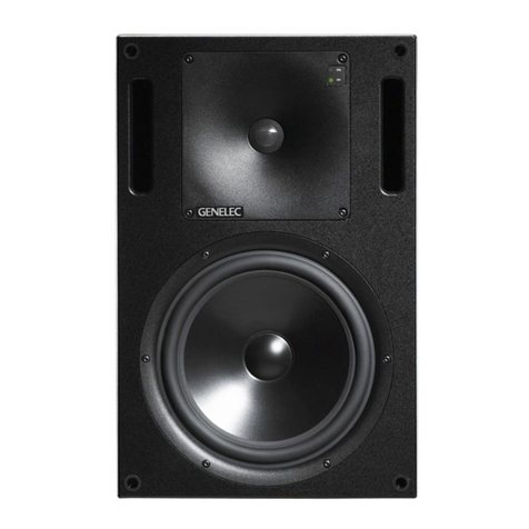
Genelec response controls User manual

Performance Comparison of Graphic
Equalisation and Active Loudspeaker Room
Response Controls
Andrew Goldberg and Aki Mäkivirta
Genelec Oy, Olvitie 5, 74100 Iisalmi, Finland
ABSTRACT
We compare the room response controls available in active loudspeakers to a third-octave graphical equaliser. The
room response controls are set using an automated optimisation method presented in earlier AES publications. A
third-octave ISO frequency constant-Q graphic equaliser is set to minimise the least squares deviation from linear
within the passband in a smoothed acoustical response. The resulting equalisation performance of the two methods
is compared using objective metrics, to show how these standard room response equalising methods perform. For all
loudspeaker models pooled together, the room response controls improve the RMS deviation from a linear response
from 6.1 dB to 4.7 dB (improvement 22%), whereas graphic equalisation improves the RMS deviation to 1.8 dB
(improvement 70%). Both equalisation techniques achieve a similar improvement in the broadband balance, which
has been shown to affect a subjective lack of colouration in sound systems. The optimisation time for a graphic
equaliser is up to 48 times longer compared to that for active loudspeaker room response controls.
1. INTRODUCTION
The purpose of room equalisation is to improve the
perceived quality of sound reproduction in a listening
environment. Electronic equalisation to improve the
subjective sound quality has been widespread for at
least 40 years (an early example is [1]). Equalisation is
prevalent in professional sound reproduction such as
recording studios, mixing rooms and sound rein-
forcement. In-situ response equalisation is often im-
plemented using third-octave equalisers, which are
normally set with the help of real time analysers. This
measurement and equalisation combination is cheap,
readily available and a relatively simple concept to
grasp with a little training [2-4]. Room response cor-
recting equalisers are now also increasingly built into
active loudspeakers, but these equalisers have an en-
tirely different approach as to how the equaliser ad-
dresses any acoustic problems of the reproduction.
Since the loudspeaker-room transfer function is of
substantially higher order than the equalisation filters,
the effect of either type of equalisation is to gently
shape the acoustic response [5]. The room transfer
function is position dependent, which poses major
problems for all equalisation techniques. At high fre-
quencies the required high-resolution correction can
become very position sensitive [6,7]. Even with these
limitations, in-situ equalisers have the potential to sig-
nificantly improve perceived sound quality. The prac-
tical challenge is to find the best compromise for the
parameters in the in-situ equaliser. An acceptable
equalisation is typically a compromise to minimise the
subjective coloration in the audio due to room effects.
Despite advances in psychoacoustics, it is difficult to
quantify what the listener actually perceives the sound
quality to be [8-10], or to optimise equalisation based
on that evaluation. Because of this, in-situ equalisation
typically attempts to obtain the best fit to some objec-

GOLDBERG AND MÄKIVIRTA OPTIMISED EQUALISATION COMPARISON
AES 116TH CONVENTION, BERLIN, GERMANY, 2004 MAY 8-11 2
tively measurable target known to relate to the percep-
tion of sound as being free from coloration, such as a
flat third-octave smoothed magnitude response.
The purpose of this paper is to investigate how the
standard room response controls available in active
loudspeakers [11] compare to the industry standard
method for sound system equalisation, i.e. a 31-band
third-octave graphic equaliser. It is obvious that a
graphical equaliser has many more adjustment degrees
of freedom compared to the standard room response
equalisers employed in active loudspeakers – there are
31 gains with fixed Q’s and centre frequencies in a
graphical equaliser compared to some three to five
separate settings with two to seven discrete values in
the room response equaliser. This would appear to
suggest that a graphical equaliser should achieve a su-
perior outcome if set properly. However, the centre
frequencies, and fixed Q, of a graphical equaliser are
not designed to cope with typical room response prob-
lems and it is rather naïve to simply suggest that the
higher degrees of freedom alone could be taken as an
indication of how much better or worse one method is
compared to another.
This paper presents a performance comparison of a
room response control set available in active loud-
speakers and a standard 31-band graphic equaliser.
Optimisation algorithms are used to set both equalis-
ers to achieve the best possible fit to the desired flat
in-room magnitude response. To make possible this
comparison, an optimisation algorithm was developed
to set the gains of a 31-band graphical equaliser. This
method is described. The performance of the equalisa-
tions and optimisation algorithms is investigated by
studying the statistical properties of 67 in-situ magni-
tude responses before and after equalisation.
2. IN-SITU EQUALISATION
The room response controls were previously described
in [12-14]. A constant-Q type 31-band DSP graphic
equaliser [15] was constructed using bi-quadratic
transfer functions of the form,
2
2
1
1
2
2
1
10
1
)( −−
−−
++
++
=zaza zbzbb
zH (1)
where the scaling of the transfer function is given by
the coefficients,
()
20
0
0
10
2
2sin
1
G
S
A
QA /ff
a
=
+=
π
(2)
with the centre frequency f0, sampling frequency fS,
gain of the resonance A, calculated from the dB-gain
value G, and the resonance goodness Q. The filter co-
efficients are then defined as,
(
)
()
()
()
()
0
0
2
0
0
1
0
0
2
0
0
1
0
0
0
2
2sin
1
2cos2
2
2sin
1
2cos2
2
2sin
1
aQA /ff
a
a/ff
a
aQ/ff
A
b
a/ff
b
aQ/ff
A
b
S
S
S
S
S
⎟
⎟
⎠
⎞
⎜
⎜
⎝
⎛−
=
−
=
⎟
⎟
⎠
⎞
⎜
⎜
⎝
⎛−
=
−
=
⎟
⎟
⎠
⎞
⎜
⎜
⎝
⎛+
=
π
π
π
π
π
(3)
where f0is set to the centre frequency of each of the
31 filter bands according to ISO and IEC [16,17].
These standards do not explicitly define the Q, instead
a magnitude response tolerance is given to allow for
design differences between manufacturers. For this
study Q= 4.33,
33.4
1010 10 05.005.0
0=
−
== −+ nn
n
B
f
Q(4)
where nis a value that gives the third-octave band
centre frequency, e.g. n= 3 for 1 kHz, and Bis the
bandwidth of the third-octave resonance.
As is common practice in most commercially avail-
able hardware, the gain Gis bound between 0 and –12
dB. Note that contrary to most hardware solutions, no
positive gain is allowed and there is no overall make-
up gain to compensate for broadband attenuation. En-
gineers commonly use this technique to avoid over-
loading the loudspeaker.
3. OPTIMISATION OF THE EQUALISATION
3.1. Room Response Control Optimiser
The five-stage algorithm previously described in
[12,14] to find optimal settings for room response
control exploits the heuristics of experienced system
calibration engineers, thereby achieving computa-
tional efficiency by avoiding unrealistic filter setting
combinations. A fast optimisation time is also
achieved by breaking down the process into stages.

GOLDBERG AND MÄKIVIRTA OPTIMISED EQUALISATION COMPARISON
AES 116TH CONVENTION, BERLIN, GERMANY, 2004 MAY 8-11 3
3.2. Graphic Equaliser Optimiser
With Qand centre frequency f0fixed for each third-
octave band, the remaining variable available for ad-
justment is the gain G. This is bound between 0 and –
12 dB. A least squares method, Matlab’s
“lsqnonlin” function [18], minimises the objective
function,
df
fx
fxfa
Ef
ff
m
m
2
0
2
1)(
)()(
min ∫
=
=(5)
where x(f) is the third-octave smoothed [19] magni-
tude of the loudspeaker in-situ frequency response,
am(f) is the graphic equaliser magnitude response, x0(f)
is the target response and frequencies f1and f2define
the optimisation band, i.e. –3 dB lower cut-off fre-
quency for the loudspeaker in question and the high
frequency limit for the optimisation at 15 kHz.
The optimised filter values are rounded after optimisa-
tion to the nearest 0.1dB, as this is the typical gain
resolution found in commercially available DSP
graphic equalisers [20]. These values are used to filter
the in-situ loudspeaker response prior to statistical
analysis.
Visual inspection of the optimised responses shows
that the algorithm is robust to finding the global mini-
mum.
3.3. Computational Load
Optimisation speed was tested on a Pentium M 1.6
GHz based computer. The room response equaliser
optimisation algorithm runs in about 1.5–3 s depend-
ing on the loudspeaker model, whereas the graphical
equaliser optimisation algorithm takes 30–60 s, i.e.
10…20 times longer. The longer run time is explained
by the higher degrees of freedom in a graphical equal-
iser. The large optimisation time variation is due to
differing in-situ responses causing variations in the
run time because the optimisation continues until the
required fitting tolerance is achieved.
4. METHODS
4.1. Statistical Data Analysis
To assess the performance of the combination of
optimisation algorithm and equalisation in the
loudspeakers, the analysis compares the unequalised
in-situ magnitude response to the equalised response.
The third-octave smoothed magnitude response was
calculated. The optimal room response control settings
were calculated for each loudspeaker response. Statis-
tical data was recorded for each magnitude response
measurement before and after equalisation to study
how the objective quality was improved. Further sta-
tistical analysis is conducted on all measurements in
three frequency bands (Table 1) “LF”, “MF” and
“HF”, collectively called “subbands” and correspond-
ing roughly to the bandwidths for each driver in a
three-way system.
Table 1. Frequency band definitions the statistical data
analysis: fLF is the frequency of the lower –3 dB limit
of the frequency range.
Frequency Range Limit
Bandwidth Name Low High
Broadband fLF 15 kHz
LF fLF 400 Hz
MF 400 Hz 3.5 kHz
HF 3.5 kHz 15 kHz
For each loudspeaker, the broadband median pressure
is calculated. Pressure deviations from this median are
recorded within each subband and for the broadband.
These deviations are then used to describe the proper-
ties and extent of deviations from a flat response. Me-
dians calculated for subbands, defined above, are re-
corded. The differences from the broadband median to
subband medians are calculated and then used as an
indicator for broadband balance of the frequency re-
sponse. Both statistical descriptors are recorded before
and after equalisation for each frequency band and
each equalisation method.
The quartile difference and RMS deviation are calcu-
lated for the four loudspeaker categories determined
by the type of built-in room response controls in the
loudspeakers. Both the quartile difference and RMS
deviation values represent two slightly different ways
to look at the deviation from the median value of the
distribution. The quartile values are more robust to
outlier values while the RMS values include these ef-
fects.
4.2. Data Analysis Case Study
Figure 5 in Appendix C shows the third-octave
smoothed and unsmoothed in-situ response of a large
soffit mounted system [5]. The measurement tech-
nique is detailed in [12,14].
4.2.1. Room Response Control Equalisation
Appendix A shows a case example where the room
response control settings are calculated according to
the optimisation algorithm [12-14]. The equalisation
target is a flat magnitude response, i.e. a straight line
at 0 dB level. The loudspeaker’s passband (triangles)
and the frequency band of equalisation (crosses) are

GOLDBERG AND MÄKIVIRTA OPTIMISED EQUALISATION COMPARISON
AES 116TH CONVENTION, BERLIN, GERMANY, 2004 MAY 8-11 4
indicated on the graphical output (Figure 2). The con-
trol settings and before and after equalisation re-
sponses are shown. The treble tilt, midrange level and
bass tilt controls have been set. The equalisation cor-
rects the low frequency alignment and improves the
linearity across the whole passband.
Figure 3 in Appendix A shows a statistical analysis of
the same loudspeaker presented in graphical form.
The upper three plots were calculated before equalisa-
tion and the lower three plots after equalisation. The
three types of plot display outliers and percentiles in
the magnitude value distribution (box plot), the histo-
gram of values, with a 1 dB resolution, and the fit of
the magnitude values to a normal distribution. These
plots show that the distribution in the magnitude data
has been reduced. This is illustrated by the reduced
range in the box plot and the value histogram and a
steeper curve in the normal probability plot. The fit to
a normal distribution is shown but not discussed fur-
ther. The time taken for the optimisation was 2.43 s.
4.2.2. Graphic Equalisation
Appendix C shows the same case example as above,
but using a graphic equaliser with settings calculated
according the algorithm detailed in Section 3.2. The
settings are shown in Table 2 and plotted in Figure 6.
The effect on the in-situ response can be seen in
Figure 7. Most of the equalisation takes place below
100Hz but some minor adjustment in the in-situ re-
sponse is also made in the midrange to compensate for
resonances due to room modes or constructive inter-
ference due to reflections. An improved linearity
across the whole passband is seen and, in particular,
the low frequency alignment has become better. The
statistical analysis shown in Figure 8 demonstrates
that the magnitude distribution has been reduced. This
is illustrated by the reduced range in the box plot and
the value histogram, and the steeper curve in the nor-
mal probability plot. The time taken for the optimisa-
tion was 29.66 s.
4.2.3. Equalisation Comparison
Comparing the two equalisation techniques, the box
plot, histogram and steeper line in the normal prob-
ability plot all indicate that the distribution of the data
is smaller when graphic equalisation is used. The
room response controls do achieve a good broadband
balance (Figure 2) but the finer detail is not corrected.
In addition to an improved broadband balance,
graphic equalisation is able to correct for local fea-
tures in the response (Figure 7) but only with limited
success. Resonances due to room modes or construc-
tive interference due to reflections in the response
cannot be corrected accurately when the frequencies
do not coincide with the centre frequencies of third-
octave filter bands. A good example of this can be
seen at 600 Hz.
In the room response control equalisation, bass boost
caused by soffit mounting the loudspeaker is corrected
using a single bass tilt filter control set to –8 dB.
Graphic equalisation requires seven filters for this al-
though better low frequency linearity is seen. It is
clear that accurately setting a combination of seven
filters is not a trivial task, especially if time is at a pre-
mium.
The distribution of the room response control equali-
sation’s magnitude response (Figure 3) differs from
the graphic equalisation’s magnitude response (Figure
8). In the latter, there is a skew towards negative val-
ues as only negative gain can be applied to the re-
sponse. In other words, the upward deviations (reso-
nances or constructive interference) are equalised and
the downward deviations (antiresonances or destruc-
tive interference) are not.
The graphic equaliser optimisation took 12.2 times
longer than that for the room response equalisation
optimisation.
5. RESULTS
A total of 67 loudspeakers were measured before and
after equalisation. Of these, 12 were small two-way
systems, 22 were two-way systems, 30 were three-
way systems and three were large systems.
5.1. Room Response Control Equalisation
The detailed results of a statistical analysis for the in-
dividual loudspeakers were discussed in detail in [13].
The subband median levels (Figure 1) illustrate the
broadband frequency balance between the subbands.
Loudspeaker loading from nearby boundaries is re-
flected in the LF subband median level before equali-
sation, especially in the often flush-mounted three-
way and large models. Cancellations from nearby
boundaries are reflected in the low median value of
the LF subband of the small two-way and two-way
systems.
High median levels in the LF subband are reduced af-
ter equalisation, which indicates that equalisation
compensates well for the loudspeaker loading, how-
ever cancellations cannot be equalised. Improvements
in the flatness across subbands of the average subband
median level demonstrates that equalisation can im-
prove the broadband flatness. The largest improve-
ment is seen in the three-way and large systems. The
broadband flatness improvement is mainly the result
of better alignment of the LF subband with the MF
and HF subbands, and a reduction of variation in the

GOLDBERG AND MÄKIVIRTA OPTIMISED EQUALISATION COMPARISON
AES 116TH CONVENTION, BERLIN, GERMANY, 2004 MAY 8-11 5
LF subband as indicated by the smaller errors bars.
For all loudspeakers pooled together (Figure 1), the
equalisation reduces the variance in the median level
for the LF subband. In Figure 4, Appendix B, the re-
sults are pooled for all products and for each product
type. The change in quartile difference and RMS de-
viation for the broadband and the subbands is illus-
trated. Across all models, the broadband flatness is
improved by 1.4 dB and the mean reduction in the LF
subband RMS deviation is 2.0 dB.
The average time taken for room response control
optimisation is 1.83 s ± 0.68 s. The best case is 1.12 s
and the worst case is 2.97 s.
Median Levels in Subbands - Small Two-way Systems
-6
-4
-2
0
2
4
6
8
LF MF HF LF MF HF LF MF HF
Original Room Reponse Controls Graphic Equaliser
Median Levels in Subbands - Three-way Systems
-6
-4
-2
0
2
4
6
8
LF MF HF LF MF HF LF MF HF
Original Room Reponse Controls Graphic Equaliser
Median Levels in Subbands - Two-way Systems
-6
-4
-2
0
2
4
6
8
LF MF HF LF MF HF LF MF HF
Original Room Reponse Controls Graphic Equaliser
Median Levels in Subbands - All Systems
-6
-4
-2
0
2
4
6
8
LF MF HF LF MF HF LF MF HF
Original Room Reponse Controls Graphic Equaliser
Median Levels in Subbands - Large Systems
-6
-4
-2
0
2
4
6
8
LF MF HF LF MF HF LF MF HF
Original Room Reponse Controls Graphic Equaliser
Figure 1. Mean and standard deviation of subband median levels before and after room response control and graphic
equalisation.
5.2. Graphic Equalisation
Appendix D (Figures 9-13) depicts the use of the
equaliser controls for each loudspeaker group. The
upper graph (a) shows how the graphic equaliser is
used including the use of 0 dB settings. The lower
graph (b) shows how it is used excluding the use of 0
dB settings and therefore demonstrates how much EQ
is required when it is used. Values for the 16 kHz and
20 kHz bands can be ignored as they are outside the
optimisation frequency range in all cases.
The small two-way models (Figure 9) show a general
trend of bass reduction, –3 to –5 dB, but with some
additional large midrange adjustments and small high
frequency balancing. The standard deviations are
large, indicating that there is little consistency in the
required equalisation across loudspeakers.
The two-way models (Figure 10) show a general trend
of bass reduction, –2 to –4 dB, slightly less midrange
reduction, –1 to –2 dB, adjustment and small high fre-
quency shelving too. Equalisation is required in lower
frequency bands as these systems have a deeper bass
extension. The standard deviations are small indicat-
ing that there is more consistency in the required
equalisation across loudspeakers. In general, less
equalisation is required than for the small two-way
systems.

GOLDBERG AND MÄKIVIRTA OPTIMISED EQUALISATION COMPARISON
AES 116TH CONVENTION, BERLIN, GERMANY, 2004 MAY 8-11 6
Similar trends are seen for the three-way systems
(Figure 11) except that the bass reduction averages –3
to –5 dB and some additional roll-off shape is seen at
the very lowest frequencies of the loudspeakers.
As there were only three large system responses
(Figure 12), all taken from same room, the standard
deviations indicate the equalisation consistency.
Across all of the loudspeakers (Figure 13), the general
trend is a need for approximately 3 dB to 4 dB of bass
attenuation, 2 dB from 200 Hz to 500 Hz and only 1
dB above 500 Hz. A 0 to –12 dB gain range is suffi-
cient. Across the whole study, only one of the third-
octave bands inside the optimisation frequency range
was set to the maximum attenuation, –12 dB.
The subband median levels (Figure 1) demonstrate
that a high median level in the LF subband is reduced
by the equalisation. This indicates that equalisation
compensates for acoustical loading of the loudspeaker.
The better match across subbands of the average sub-
band median level demonstrates that equalisation has
improved the broadband flatness, and the largest im-
provement is seen in the three-way and large systems.
The broadband flatness improvement is mainly the
result of better alignment of the LF subband with the
MF and HF subbands. The equalisation has reduced
the variation between subbands and also improved the
broadband flatness of the acoustical response. For all
loudspeakers pooled together, the equalisation reduces
the variance in the median level for the LF subband.
In Figure 14, Appendix E, the results are pooled for
all products and for each product type. The change in
quartile difference and RMS deviation for the broad-
band and the subbands is illustrated. For all models,
the broadband flatness is improved by 4.3 dB and the
mean reduction in the LF subband RMS deviation im-
provement is 5.9 dB. The graphic equaliser is able to
compensate, to some extent, the severe anomalies at-
tributable to extremely bad room acoustic conditions
seen within some of the pre-equalisation responses.
The average time taken for graphic equalisation
optimisation is 31.40 s ± 16.64 s. The best case is
14.61 s and the worst case is 116.29 s.
5.3. Equalisation Comparison
Appendix F, Figure 15, represents the difference be-
tween the change in sound level deviation due to the
room response controls and the graphic equalisation
techniques. For each subband, quartile difference and
RMS deviation from the median are plotted. A value
below 0 dB indicates that graphic equalisation
achieves a response closer to the target. For all loud-
speaker models pooled together, the room response
controls improved the RMS deviation from 6.1 dB to
4.7 dB (improvement 22%), whereas graphic equalisa-
tion improved the RMS deviation to 1.8 dB (im-
provement 70%). The main improvement is seen at
low frequencies. The better performance by the
graphic equaliser is achieved by using between five
(large loudspeakers) and ten times (small two-ways)
more equalisation stages and far longer optimisation
times.
The additional time it takes to perform the graphic
equalisation optimisation compared to room response
equalisation optimisation is 18.54 ± 8.49 times longer.
The best case is 8.35 times longer and the worst case
is 47.97 times longer.
6. DISCUSSION
The room response controls in active loudspeakers
implement discrete filter parameter values rather than
a continuous parameter value range. A 31-band
graphic equaliser typically allows for control of the
gain in each of the third-octave centred bands over a
range of ±12 dB and an overall make-up gain over the
same range. In this study the gains were constrained to
a range of 0 to –12 dB and a least squares optimisa-
tion algorithm designed for selecting the optimal set-
tings.
The statistical analysis of 67 in-situ loudspeaker re-
sponses shows that both equalisation methods achieve
a smaller RMS deviation from the target response.
The improvement is limited by the equalisers’ inabil-
ity to correct for narrow-band deviations in a magni-
tude response. There is little improvement in the quar-
tile differences and RMS deviations in the MF and HF
subbands. This is because room related response
variations are too narrow band to be corrected by a
third-octave graphic equaliser or the room response
control equaliser. The largest improvement is seen in
the three-way and large systems. This suggests that
better room acoustics, leading to a reduced loud-
speaker-room interaction, allows the equalisation
methods to operate more effectively.
The room response controls in the active loudspeakers
achieve a good broadband balance but the fine detail
is not corrected. Correcting fine detail may not be
very significant because human hearing is more sensi-
tive at detecting wideband imbalances than narrow
band deviations in the magnitude response [21, 22].
In an acoustically good room, the room response con-
trols built into an active loudspeaker allow for good
control of the broadband balance. A good example of
this can be seen in averaged median values of the
large systems (Figure 1) where the three responses
show good balancing and relatively little variance.
Even the three-way systems show a balancing within a
1.5dB window with relatively low variance. This is

GOLDBERG AND MÄKIVIRTA OPTIMISED EQUALISATION COMPARISON
AES 116TH CONVENTION, BERLIN, GERMANY, 2004 MAY 8-11 7
also the probable cause for improving performance
towards larger systems (Figures 4 and 14) shown by a
similar trend across both equalisation methods. This
underlines the importance of primarily solving acous-
tical problems by treating the room before trying to
use equalisers.
Graphic equalisation can yield a somewhat flatter re-
sponse, but multiple filter bands may be required to
correct for large features in the response. Some up-
ward deviations in the response, due to resonances or
constructive interference, cannot be corrected accu-
rately when they do not coincide with the graphical
equaliser’s centre frequencies. This complexity of
graphical equalisers makes manual gain setting com-
plex and therefore more prone to operator error. When
using computerised optimisation, the time to calculate
a graphical equaliser’s settings was 8-48 times longer
than the time to select the best room response control
settings.
Graphic equalisation achieves LF subband results
closer to the target. Both equalisation techniques
achieved a similar improvement in the broadband bal-
ance, which has previously been shown to determine a
subjective lack of colouration in sound systems.
7. CONCLUSIONS
The objective of this paper is to compare the perform-
ance of the industry standard 31-band graphic equal-
iser to the room response controls built into active
loudspeakers. Both equalisation techniques achieved a
similar improvement in the broadband balance, which
has previously been shown to determine a subjective
lack of colouration in sound systems. For all loud-
speaker models pooled together, the room response
controls improved the RMS deviation from 6.1 dB to
4.7 dB (improvement 22%), whereas graphic equalisa-
tion improved the RMS deviation to 1.8 dB (im-
provement 70%). The graphical equaliser achieves
this improvement by using between eight (large loud-
speakers) and ten times (small two-ways) more equali-
sation stages, 8-48 times the optimisation time and
considerable increases in the financial cost.
8. ACKNOWLEDGEMENTS
The authors would like to thank Louis Fielder for the
question in a recent AES Conference in Denmark
sparking this paper’s content, Mr. Steve Fisher (SCV
London) for the original inspirational idea for the
optimiser and some of the measurements used in the
statistical analysis, Mr. Olli Salmensaari (Finnish
Broadcasting Corporation) for additional measure-
ments, Mr. Lars Morset (Morset Sound Development)
and Genelec Oy.
9. REFERENCES
[1] Boner C. P. and Boner C. R., “Minimising
Feedback in Sound Systems and Room Ring Modes
with Passive Networks,” J. Acoust. Soc. America, vol.
37, pp. 131-135 (1965 Jan).
[2] Greiner R. A. and Schoessow M., “Design As-
pects of Graphic Equalisers,” J. Audio Eng. Soc., vol.
31, pp. 394-407 (1983 Jun).
[3] Bohn D. A., “Constant-Q Graphic Equalisers,”
J. Audio Eng. Soc., vol. 34, pp. 611-626 (1986 Sep).
[4] Bohn D. A., “Operator Adjustable Equalisers:
An Overview,” Proc. 6th Int. Conf., paper 6-025 (1988
Apr).
[5] Martikainen I., Varla A. and Partanen T., “De-
sign of a High Power Active Control Room Monitor”,
86th Conv. Audio Eng. Soc., preprint 2755, (1989
Mar).
[6] Elliott S. J. and Nelson P. A., “Multiple Point
Equalisation in a Room Using Adaptive Digital Fil-
ters,” J. Acoustical Eng. Soc., vol. 37 (1989 Nov).
[7] Genereux R., “Signal Processing Considera-
tions for Acoustic Environment Correction,” Proc. UK
Conf. 1992, paper DSP-14 (1992 Sep).
[8] Holman T., “New Factors in Sound for Cinema
and Television,” J. Audio Eng. Soc., vol. 39, pp. 529-
539 (1991 Jul/Aug).
[9] Schulein R. B., “In-Situ Measurement and
Equalisation of Sound Reproduction Systems,” J. Au-
dio Eng. Soc., vol. 23, pp. 178-186 (1975 Apr).
[10] Staffeldt H. and Rasmussen E., “The Subjec-
tively Perceived Frequency Response in a Small and
Medium Sized Rooms,” SMPTE J., vol. 91, pp. 638-
643 (1982 Jul).
[11] Genelec Oy, http://www.genelec.com (2004
Feb).
[12] Goldberg A. P., Mäkivirta A., “Automated In-
Situ Frequency Response Optimisation of Active
Loudspeakers,” presented in 114th Conv. Audio Eng.
Soc., preprint 5730 (2003 March).
[13] Goldberg A. P., Mäkivirta A., “Statistical
Analysis of an Automated In Situ Frequency Response
Optimisation Algorithm for Active Loudspeakers”,
proceedings of the 23rd Conf. Audio Eng. Soc., (2003
May).
[14] Goldberg A. P., “In-Situ Frequency Response
Optimisation of Active Loudspeakers”, M.Sc. Thesis,
Helsinki University of Technology, Department of
Acoustics and Audio Signal Processing, (2004 Jan).
[15] Bristow-Johnson, R., “Cookbook formulae for
audio EQ biquad filter coefficients”,
www.harmonycentral.com / Computer / Programming/

GOLDBERG AND MÄKIVIRTA OPTIMISED EQUALISATION COMPARISON
AES 116TH CONVENTION, BERLIN, GERMANY, 2004 MAY 8-11 8
Audio-EQ-Cookbook.txt, "Peaking EQ (parametric
EQ block)” (2004 Feb).
[16] ISO 266:1997 “Acoustics – Preferred Frequen-
cies, 2nd Ed”, International Standards Organisation,
Geneva (1997).
[17] IEC 1260: 1995-07: “Electroacoustics - Oc-
tave-band and fractional-octave-band filters, 1st Ed”,
International Electrotechnical Commission, Geneva
(1995).
[18] The MathWorks, “MATLAB Optimisation
Toolbox (v.2.3)”, The MathWorks Inc., Natick,
(2003).
[19] Moore B. C. J., Glasberg B. R., Plack C. J. and
Biswas A. K., “The shape of the Ear’s Temporal Win-
dow,” J. Acoustical Soc. America, vol. 83, pp. 1102-
1116 (1988 Mar).
[20] Klark Technik, http://www.klarkteknik.com,
(2004 Feb).
[21] Toole F. E., Olive S. E., “The Modification of
Timbre by Resonances: Perception and Measure-
ment”, J. Audio Eng. Soc., vol. 36, pp. 122-141 (1988
Mar.).
[22] Olive S. E., Schuck P. L., Ryan J. G, Sally S.
L., Bonneville M. E., “The Detection Thresholds of
Resonances at Low Frequencies”, J. Audio Eng. Soc.,
vol. 45, pp. 116-127 (1997 Mar.).

GOLDBERG AND MÄKIVIRTA OPTIMISED EQUALISATION COMPARISON
AES 116TH CONVENTION, BERLIN, GERMANY, 2004 MAY 8-11 9
APPENDIX A – ROOM RESPONSE CONTROL CASE STUDY, STATISTICAL GRAPHS
Figure 2. Case study optimisation results using room response control equalisation.
Figure 3. Case study statistical output – box plot, histogram and normal probability plot before (upper) and after
(lower) optimised room response control equalisation.

GOLDBERG AND MÄKIVIRTA OPTIMISED EQUALISATION COMPARISON
AES 116TH CONVENTION, BERLIN, GERMANY, 2004 MAY 8-11 10
APPENDIX B – MODEL GROUPED ROOM RESPONSE CONTROL EQUALISATION SUMMARY
25% to 75% Percentile Difference Change
due to Room Response Control Equalisation
-15
-10
-5
0
5
Broad
LF
MF
HF
RMS Deviation Change
due to Room Response Control Equalisation
-15
-10
-5
0
5
Broad
LF
MF
HF
Figure 4. Change in sound level deviation due to Room Response Control equalisation for each subband and the
broadband, quartile difference and RMS of deviation from the broadband median. The error bar indicates the stan-
dard deviation.
ALL Small Two-way Three-way Large
ALL Small Two-way Three-way Large

GOLDBERG AND MÄKIVIRTA OPTIMISED EQUALISATION COMPARISON
AES 116TH CONVENTION, BERLIN, GERMANY, 2004 MAY 8-11 11
APPENDIX C – GRAPHIC EQUALISER CASE STUDY, STATISTICAL GRAPHS
Magnitude Frequency Response - Finland, Gen Auditorium, 1036A, Left
Frequency [Hz]
10 100 1,000 10,000
Pres. [Pa] / [volts], dB
25
20
15
10
5
0
-5
-10
Figure 5. Unequalised in-situ acoustic measurement with smoothed and unsmoothed data.
Table 2. Graphic equaliser settings.
Centre
Frequency,
Hz Gain, dB
Centre
Frequency,
Hz Gain, dB
Centre
Frequency,
Hz Gain, dB
Centre
Frequency,
Hz Gain, dB
20 -1.6 200 -0.7 2,000 0.0 20,000 0.0
25 -6.6 250 0.0 2,500 -0.1
32 -7.7 315 0.0 3,150 0.0
40 -1.4 400 0.0 4,000 0.0
50 -2.1 500 -0.2 5,000 0.0
63 -8.2 630 -1.3 6,300 0.0
80 -3.3 800 0.0 8,000 0.0
100 0.0 1,000 0.0 10,000 0.0
125 0.0 1,250 0.0 12,500 0.0
160 -0.9 1,600 0.0 16,000 0.0
Use of Graphic Equaliser - 1036AL
-12
-11
-10
-9
-8
-7
-6
-5
-4
-3
-2
-1
0
1
2
3
20
25
32
40
50
63
80
100
125
160
200
250
315
400
500
630
800
1k
1.25k
1.6k
2k
2.5k
3.2k
4k
5k
6.3k
8k
10k
12.5k
16k
20k
1/3 Octave Frequency Band, HzLevel, dB
Figure 6. Graphic equaliser settings.

GOLDBERG AND MÄKIVIRTA OPTIMISED EQUALISATION COMPARISON
AES 116TH CONVENTION, BERLIN, GERMANY, 2004 MAY 8-11 12
Figure 7. Case study optimisation results using graphical equalisation.
Figure 8. Case study statistical output – box plot, histogram and normal probability plot before (upper) and after
(lower) optimised graphical equalisation.

GOLDBERG AND MÄKIVIRTA OPTIMISED EQUALISATION COMPARISON
AES 116TH CONVENTION, BERLIN, GERMANY, 2004 MAY 8-11 13
APPENDIX D – GRAPHIC EQUALISER STATISTICAL GRAPHS
Use of Graphic Equaliser - Small models
(incl. 0dB settings)
-12
-11
-10
-9
-8
-7
-6
-5
-4
-3
-2
-1
0
1
2
3
20
25
32
40
50
63
80
100
125
160
200
250
315
400
500
630
800
1k
1.25k
1.6k
2k
2.5k
3.2k
4k
5k
6.3k
8k
10k
12.5k
16k
20k
1/3 Octave Frequency Band, Hz
Level, dB
Figure 9a. Use of the graphic equaliser for small 2-way systems – including 0dB settings.
Use of Graphic Equaliser - Small models
(excl. 0dB settings)
-15
-14
-13
-12
-11
-10
-9
-8
-7
-6
-5
-4
-3
-2
-1
0
1
2
3
20
25
32
40
50
63
80
100
125
160
200
250
315
400
500
630
800
1k
1.25k
1.6k
2k
2.5k
3.2k
4k
5k
6.3k
8k
10k
12.5k
16k
20k
1/3 Octave Frequency Band, Hz
Level, dB
Figure 9b. Use of the graphic equaliser for small 2-way systems – excluding 0dB settings.

GOLDBERG AND MÄKIVIRTA OPTIMISED EQUALISATION COMPARISON
AES 116TH CONVENTION, BERLIN, GERMANY, 2004 MAY 8-11 14
Use of Graphic Equaliser - 2-way models
(incl. 0dB settings)
-12
-11
-10
-9
-8
-7
-6
-5
-4
-3
-2
-1
0
1
2
3
20
25
32
40
50
63
80
100
125
160
200
250
315
400
500
630
800
1k
1.25k
1.6k
2k
2.5k
3.2k
4k
5k
6.3k
8k
10k
12.5k
16k
20k
1/3 Octave Frequency Band, Hz
Level, dB
Figure 10a. Use of the graphic equaliser for 2-way systems – including 0dB settings.
Use of Graphic Equaliser - 2-way models
(excl. 0dB settings)
-15
-14
-13
-12
-11
-10
-9
-8
-7
-6
-5
-4
-3
-2
-1
0
1
2
3
20
25
32
40
50
63
80
100
125
160
200
250
315
400
500
630
800
1k
1.25k
1.6k
2k
2.5k
3.2k
4k
5k
6.3k
8k
10k
12.5k
16k
20k
1/3 Octave Frequency Band, Hz
Level, dB
Figure 10b. Use of the graphic equaliser for 2-way systems – excluding 0dB settings.

GOLDBERG AND MÄKIVIRTA OPTIMISED EQUALISATION COMPARISON
AES 116TH CONVENTION, BERLIN, GERMANY, 2004 MAY 8-11 15
Use of Graphic Equaliser - 3-way models
(incl. 0dB settings)
-12
-11
-10
-9
-8
-7
-6
-5
-4
-3
-2
-1
0
1
2
3
20
25
32
40
50
63
80
100
125
160
200
250
315
400
500
630
800
1k
1.25k
1.6k
2k
2.5k
3.2k
4k
5k
6.3k
8k
10k
12.5k
16k
20k
1/3 Octave Frequency Band, Hz
Level, dB
Figure 11a. Use of the graphic equaliser for 3-way systems – including 0dB settings.
Use of Graphic Equaliser - 3-way models
(excl. 0dB settings)
-15
-14
-13
-12
-11
-10
-9
-8
-7
-6
-5
-4
-3
-2
-1
0
1
2
3
20
25
32
40
50
63
80
100
125
160
200
250
315
400
500
630
800
1k
1.25k
1.6k
2k
2.5k
3.2k
4k
5k
6.3k
8k
10k
12.5k
16k
20k
1/3 Octave Frequency Band, Hz
Level, dB
Figure 11b. Use of the graphic equaliser for 3-way systems – excluding 0dB settings.

GOLDBERG AND MÄKIVIRTA OPTIMISED EQUALISATION COMPARISON
AES 116TH CONVENTION, BERLIN, GERMANY, 2004 MAY 8-11 16
Use of Graphic Equaliser - Large models
(incl. 0dB settings)
-12
-11
-10
-9
-8
-7
-6
-5
-4
-3
-2
-1
0
1
2
3
20
25
32
40
50
63
80
100
125
160
200
250
315
400
500
630
800
1k
1.25k
1.6k
2k
2.5k
3.2k
4k
5k
6.3k
8k
10k
12.5k
16k
20k
1/3 Octave Frequency Band, Hz
Level, dB
Figure 12a. Use of the graphic equaliser for large systems – including 0dB settings.
Use of Graphic Equaliser - Large Models
(excl. 0dB settings)
-15
-14
-13
-12
-11
-10
-9
-8
-7
-6
-5
-4
-3
-2
-1
0
1
2
3
20
25
32
40
50
63
80
100
125
160
200
250
315
400
500
630
800
1k
1.25k
1.6k
2k
2.5k
3.2k
4k
5k
6.3k
8k
10k
12.5k
16k
20k
1/3 Octave Frequency Band, Hz
Level, dB
Figure 12b. Use of the graphic equaliser for large systems – excluding 0dB settings.

GOLDBERG AND MÄKIVIRTA OPTIMISED EQUALISATION COMPARISON
AES 116TH CONVENTION, BERLIN, GERMANY, 2004 MAY 8-11 17
Use of Graphic Equaliser - All Models
(incl. 0dB settings)
-12
-11
-10
-9
-8
-7
-6
-5
-4
-3
-2
-1
0
1
2
3
20
25
32
40
50
63
80
100
125
160
200
250
315
400
500
630
800
1k
1.25k
1.6k
2k
2.5k
3.2k
4k
5k
6.3k
8k
10k
12.5k
16k
20k
1/3 Octave Frequency Band, Hz
Level, dB
Figure 13a. Use of the graphic equaliser for all systems – including 0dB settings.
Use of Graphic Equaliser - All Models
(excl. 0dB settings)
-15
-14
-13
-12
-11
-10
-9
-8
-7
-6
-5
-4
-3
-2
-1
0
1
2
3
20
25
32
40
50
63
80
100
125
160
200
250
315
400
500
630
800
1k
1.25k
1.6k
2k
2.5k
3.2k
4k
5k
6.3k
8k
10k
12.5k
16k
20k
1/3 Octave Frequency Band, Hz
Level, dB
Figure 13b. Use of the graphic equaliser for all systems – excluding 0dB settings.

GOLDBERG AND MÄKIVIRTA OPTIMISED EQUALISATION COMPARISON
AES 116TH CONVENTION, BERLIN, GERMANY, 2004 MAY 8-11 18
APPENDIX E – MODEL GROUPED GRAPHIC EQUALISATION SUMMARY
25% to 75% Percentile Difference Change
due to Graphic Equalisation
-15
-10
-5
0
5
Broad
LF
MF
HF
RMS Deviation Change
due to Graphic Equalisation
-15
-10
-5
0
5
Broad
LF
MF
HF
Figure 14. Change in sound level deviation due to graphic equalisation for each subband and the broadband, quartile
difference and RMS of deviation from the broadband median. The error bar indicates the standard deviation.
ALL Small Two-way Three-way Large
ALL Small Two-way Three-way Large

GOLDBERG AND MÄKIVIRTA OPTIMISED EQUALISATION COMPARISON
AES 116TH CONVENTION, BERLIN, GERMANY, 2004 MAY 8-11 19
APPENDIX F – COMPARISON OF EQUALISATION TECHNIQUES SUMMARY GRAPHS
25% to 75% Percentile Difference Change
between Equalisations
-15
-10
-5
0
5
Broad
LF
MF
HF
RMS Deviation Change
between Equalisations
-15
-10
-5
0
5
Broad
LF
MF
HF
Figure 15. The difference between the change in sound level deviation for the room response control and the
graphic equalisation techniques for each subband and the broadband, quartile difference and RMS of deviation from
the broadband median are plotted. A value below 0dB indicates that graphic equalisation achieves a response closer
to the target.
ALL Small Two-way Three-way Large
ALL Small Two-way Three-way Large
Table of contents
Other Genelec Speakers manuals
Genelec
Genelec 8020D User manual

Genelec
Genelec 1038A User guide
Genelec
Genelec 8020A User manual
Genelec
Genelec 1034B User manual
Genelec
Genelec G One User manual
Genelec
Genelec 8010 User manual
Genelec
Genelec 1031A User manual
Genelec
Genelec 1032B User manual

Genelec
Genelec SAM 1238DF User manual

Genelec
Genelec 8010A User manual
Genelec
Genelec 6010A User manual
Genelec
Genelec S30DH User guide
Genelec
Genelec 1029A User manual
Genelec
Genelec 8050B User manual
Genelec
Genelec 8010A User manual
Genelec
Genelec GLM 2.0 User manual
Genelec
Genelec G Three User manual
Genelec
Genelec 8381A User manual
Genelec
Genelec 6010APM User manual

Genelec
Genelec 1038AC User manual
