Setting the tone controls
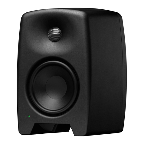
The frequency response of the Genelec M030 and
M040 can be adjusted to match the acoustic envi-
ronment by setting the tone control switches on the
rear panel. The controls are “Bass Level” and “EQ”.
Table 1 shows typical settings in various situations.
Figures 4 and 5 show the effect of the controls on
the response.
Bass Level
The Bass Level control is usually necessary when
the loudspeaker is placed near a wall. The attenu-
ation levels are -2 dB and -4 dB. The central posi-
tion of the toggle switch (Free space) suits a situa-
tion when the loudspeaker is placed far away from
walls.
EQ
The “EQ” switch has two functions (in its central posi-
tion there is no effect):
1. Tabletop EQ
This function is recommended when the loudspeak-
ers are placed on a table. Such a placement typically
causes coloration at low midrange, which the “Table-
top EQ” function is designed to compensate for.
2. Bass EQ
This function attenuates bass frequencies below
200 Hz when the loudspeaker is located near a cor-
ner. This can compensate for excessively heavy and
boomy bass reproduction.
Mounting considerations
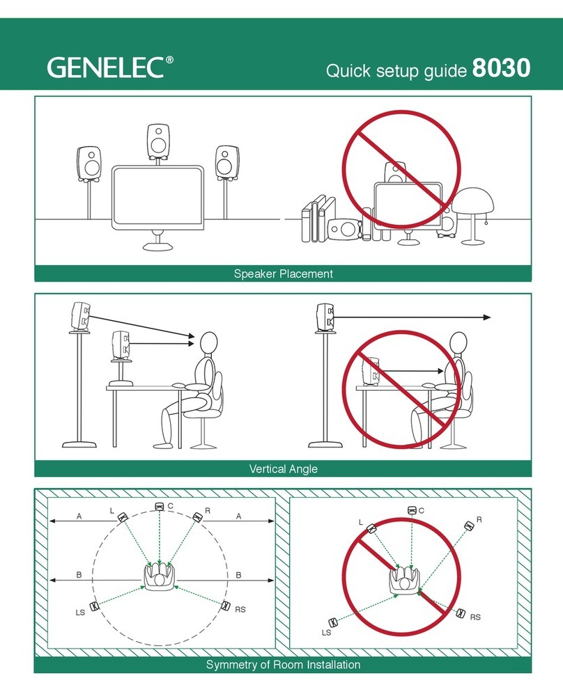
Align the loudspeakers correctly
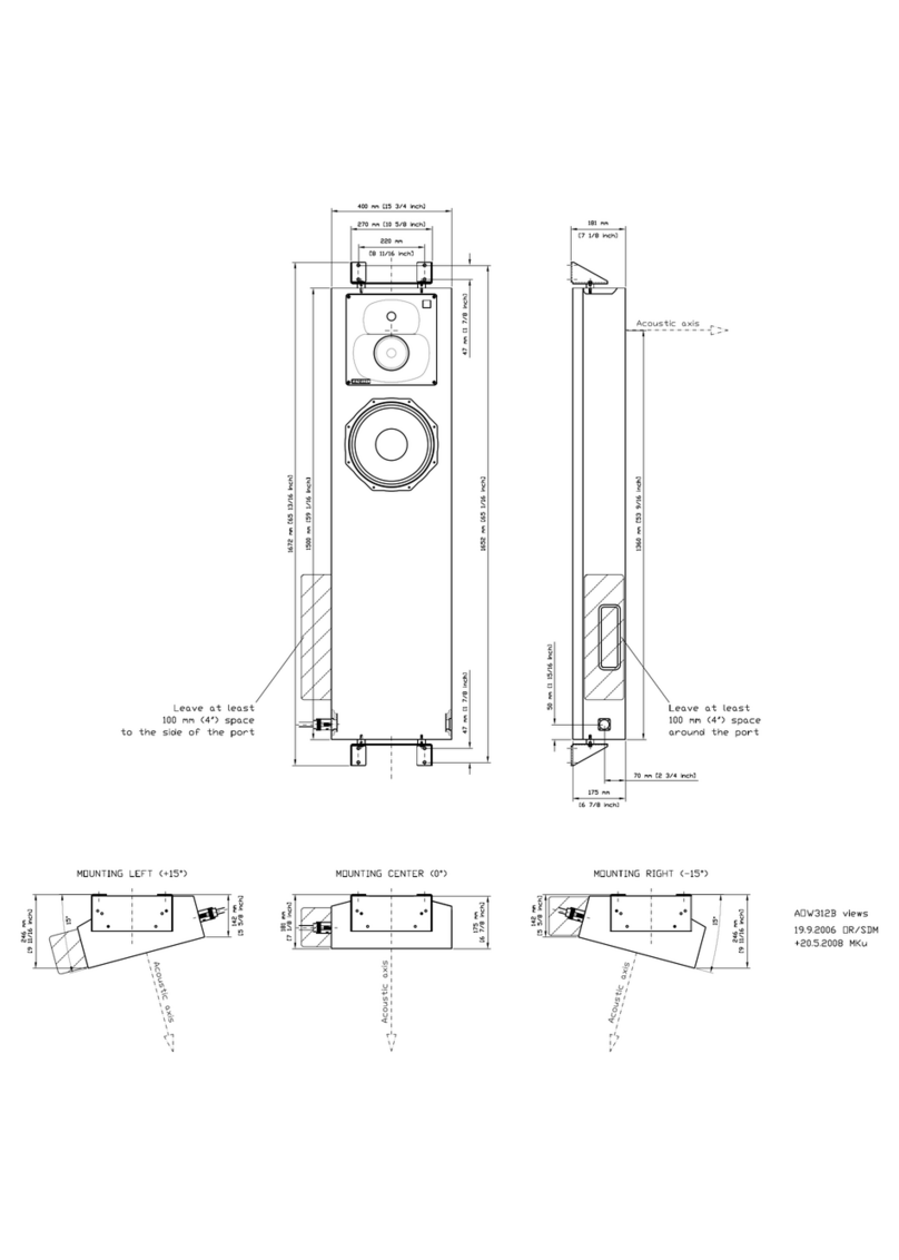
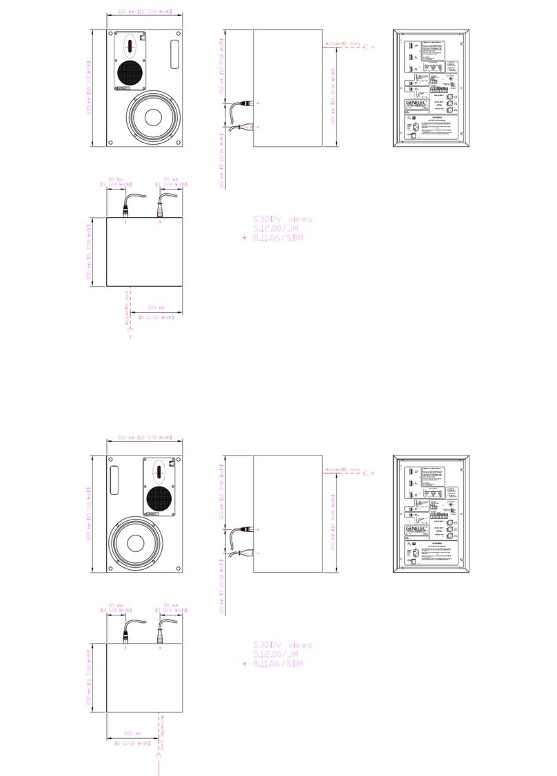
Always place the loudspeakers so that their acoustic
axes (see figure 1) are aimed towards the listening
position. Proper vertical placement is preferred, as it
provides the best linear frequency response around
the crossover frequency.
Maintain symmetry
Check that the loudspeakers are placed symmetrically
and at an equal distance from the listening position. If
possible, place the system so that the listening position
is on the centerline of the room and the loudspeakers
are placed at an equal distance from the centerline.
Minimize reflections
Acoustic reflections from objects close to the loud-
speakers like desks, cabinets, computer monitors etc.
can cause unwanted colouration of sound.This can be
minimized by placing the loudspeaker away from re-
flective surfaces. For instance, putting the loudspeak-
ers on stands behind and above the table and tilting
them down to point towards the listening position usu-
ally gives a better result than placing the loudspeakers
directly on the table.
Minimum clearances
Sufficient clearance for cooling and functioning of the
reflex ports must be ensured. The minimum clearance
Figure 3. Attach the foam patches to the underside of
the loudspeaker as shown.
of 3 centimeters (13/16”) behind, above and on both
sides of the loudspeaker is needed. The ambient tem-
perature should not rise above 35 degrees Celsius
(95°F).
The reflex ports open to the underside of the enclo-
sure. This opening must not be blocked.
Maintenance
No user serviceable parts are inside the loudspeaker.
Any maintenance or repair should only be undertaken
by qualified service personnel.
Safety considerations
M030 and M040 have been designed in accordance
with international safety standards. The following
warnings and cautions must be observed to ensure
safe operation:
• Servicing and adjustment must only be
performed by qualified service personnel.
The loudspeaker must not be opened.
• Do not expose the loudspeakers to water or
moisture. Do not place any objects filled with
liquid, such as vases, on the loudspeakers or near
them.
• These loudspeakers are capable of producing
sound pressure levels in excess of 85 dB, which
may cause permanent hearing damage.
• Free flow of air behind the loudspeakers is
necessary to maintain sufficient cooling. Do not
obstruct airflow around the loudspeakers.
• Note that the amplifier is not completely
disconnected from the AC mains service unless
the mains power cord is disconnected from the
loudspeaker or the mains outlet.
Guarantee
This product is guaranteed for a period of two years
against faults in materials or workmanship. Refer to
supplier for full sales and guarantee terms.
Compliance to FCC rules
This device complies with part 15 of the FCC Rules.
Operation is subject to the following two conditions:
This device may not cause harmful interference, and this
device must accept any interference received, including
interference that may cause undesired operation.
Note: This equipment has been tested and found to
comply with the limits for a Class B digital device, pur-
suant to part 15 of the FCC Rules. These limits are
designed to provide reasonable protection against
harmful interference in a residential installation. This
equipment generates, uses and can radiate radio fre-
quency energy and, if not installed and used in ac-
cordance with the instructions, may cause harmful
interference to radio communications. However, there
is no guarantee that interference will not occur in a
particular installation. If this equipment does cause
harmful interference to radio or television reception,
which can be determined by turning the equipment off
and on, the user is encouraged to try to correct the
interference by one or more of the following measures:
• Reorient or relocate the receiving antenna.
• Increase the separation between the equipment
and receiver.
• Connect the equipment into an outlet on a
circuit different from that to which the receiver is
connected.
• Consult the dealer or an experienced radio/TV
technician for help
Modifications not expressly approved by the manu-
facturer could void the user’s authority to operate the
equipment under FCC rules.


