Genelec HTS2 User manual

Genelec HTS2
Home Theater Subwoofer
Operating
Manual

General DescriptionGeneral Description
General DescriptionGeneral Description
General Description
The Genelec HTS2 active subwoofer is
a powerful low frequency loudspeaker
designed specially for high quality
digital 5.1 channel Home Theater
systems.
DriversDrivers
DriversDrivers
Drivers
The HTS2 utilizes two front loaded 210
mm (8") cone drivers, housed in a 55
litre vented cabinet. A cavity over the
drivers boosts the efficiency and
acoustically attenuates possible
distortion components.
CrossoversCrossovers
CrossoversCrossovers
Crossovers
A subwoofer input connector allows for
complete compatibility with digital 5.1
channel surround sound systems.
The crossover filter also provides
calibrated ‘Bass Roll-off’ and ‘Phase’
controls, minimizing the effects of the
room on the performance of the
subwoofer.
AmplifiersAmplifiers
AmplifiersAmplifiers
Amplifiers
The 180 W amplifier unit is mounted in
the rear of the cabinet on quick release
vibration isolators to ensure rattle free
operation and long term reliability. The
amplifier incorporates special
protection circuitry for driver overload
protection and convenient "autostart"
and "softclip" functions.
SoftclipSoftclip
SoftclipSoftclip
Softclip
When there are extremely high signal
levels, the amplifiers will clip and
produce audible distortion. This
distortion can be minimized using the
‘softclip’ function. This reduces the
level of the peaks in the signal before
clipping can occur and hence no
unpleasant audible distortion is heard.
The ‘softclip’ function can be enabled
or disabled as required.
AutostartAutostart
AutostartAutostart
Autostart
The ‘autostart’ function turns off the
amplifier if there is no signal present for
about 5 minutes. When the signal
returns the amplifier switches on
immediately and the speaker functions
normally. This function should be
enabled when the speaker is left turned
on even when not in use; power is saved
when the amplifier is switched off. The
‘autostart’ function can be enabled or
disabled as required.
Figure 1. Connecting the HTS2 subwoofer.
InstallationInstallation
InstallationInstallation
Installation
Once unpacked, place the subwoofer
in a suitable position (for more details
see the 'Positioning' section).
Before connecting the audio signals,
ensure that both the subwoofer and the
main speakers are switched off. Check
that the subwoofer voltage selector
switch is set to the correct voltage and
that the correct fuse for that voltage is
fitted.
Connect the subwoofer to the decoder's
line level Subwoofer Out (LFE channel)
connector (See Fig. 1 above). Audio
input is made via a 10 kOhm balanced
(XLR) or unbalanced (RCA) connector.
If the signal source has suitable
balanced outputs, we recommend
using the XLR connector and balanced
interconnect cables due to their better
resistance to interference.
Input Sensitivity SettingInput Sensitivity Setting
Input Sensitivity SettingInput Sensitivity Setting
Input Sensitivity Setting
The input sensitivity control is located
on the rear panel of the subwoofer. An
input voltage of -6dBu with a -6dBu
input sensitivity setting will produce
100dB SPL @ 1m. To obtain a 110dB
SPL output an input voltage of +10dBu
is required when the input sensitivity is
set to 0dBu.
Setting the Bass Roll-OffSetting the Bass Roll-Off
Setting the Bass Roll-OffSetting the Bass Roll-Off
Setting the Bass Roll-Off
SwitchesSwitches
SwitchesSwitches
Switches
The acoustic response of the subwoofer
may have to be matched to the
characteristics of the room in which it
will be used. To adjust the subwoofer to
match these characteristics use the
''Bass Roll-off' control switches located
on the rear panel of the subwoofer. Fig.
2 overleaf provides some suggestions
for the 'Bass Roll-off' switch settings.
When both roll-off switches are 'off', a
flat anechoic response results.
Positioning in the RoomPositioning in the Room
Positioning in the RoomPositioning in the Room
Positioning in the Room
The placement of the subwoofer in the
room will affect the overall frequency
response of the system as the effects of
the room are more apparent with low
frequencies.
The subwoofer should be placed no
further than 1 m (3' 3") from the nearest
wall. The vents of the subwoofer
(amplifier side) should face the wall.
Leave at least 10 cm (4") of free space
between the amplifier panel and any
solid object to ensure sufficient cooling.
The placement will affect the phase
difference between the main speakers
and the subwoofer, and also the bass
roll-off rate. These effects can be
compensated by the use of the controls
in the amplifier unit but consideration
should be made when placing the
subwoofer.
Choose a central and symmetrical
position for the subwoofer as this will
give an even phase match between all
main channels. Positioning the
subwoofer close to a corner should be
avoided as it will boost the bass level at
lower frequencies and may cause
asymmetrical spatial imaging.
See Fig. 2 'Subwoofer Positioning'
overleaf for examples of recommended
positions within a room.

11
11
1 Recommended position.
22
22
2 Positioning the subwoofer in a corner causes a bass
frequency boost.
33
33
3 This arrangement may cause a loss in low
frequencies if the distance from the listening position
to the front wall is between 1 and 3 m (3'3" - 10').
44
44
4 The 'Soffit', flush mount or cabinet mount is also
recommended. Here the vents must radiate into
the room.
Safety ConsiderationsSafety Considerations
Safety ConsiderationsSafety Considerations
Safety Considerations
- Servicing and adjustment should
only be performed by qualified
service personnel.
- Opening the amplifier's rear panel
is strictly prohibited.
- It is forbidden to use this product
with an unearthed mains cable,
which may lead to personal injury.
- Do not expose the unit to water or
moisture.
Warning!
This equipment is capable of delivering
sound pressure levels in excess of
85dB, which may cause permanent
hearing damage.
MaintenanceMaintenance
MaintenanceMaintenance
Maintenance
No user serviceable parts are to be
found within the amplifier unit. Any
maintenance of the unit should only be
undertaken by qualified service
personnel. Ensure that if fuse
replacement is required, only fuses of
the appropriate voltage and current
ratings are used. REMEMBER to
disconnect the power supply by
removing the mains cable before fuse
replacement.
GuaranteeGuarantee
GuaranteeGuarantee
Guarantee
This product is supplied with a two year
guarantee against manufacturing faults
or defects that might alter the
performance of the unit. Refer to supplier
for full sales and guarantee terms.
Figure 2. Subwoofer positioning and suggested "Bass roll-off"
settings. Unless mentioned otherwise, the vents of the subwoofer
should face towards the nearest wall.
Setting the PhaseSetting the Phase
Setting the PhaseSetting the Phase
Setting the Phase
ControlControl
ControlControl
Control
The effect of incorrect phase alignment
between main speakers and subwoofer
is a drop in the frequency response of
the whole system at the crossover
frequency. The graphs below (figure 3)
Figure 3. The effect of phase difference
between the subwoofer and the main
loudspeakers
show the effect of phase difference on
the frequency response.
The phase difference between the main
speakers and subwoofer at the listening
position is dependent upon the
positioning of the subwoofer. To avoid
phase differences between the left and
right channels and the subwoofer, the
subwoofer should be placed at the
center of the front speaker array.
Coarse Phase Correction MethodCoarse Phase Correction Method
Coarse Phase Correction MethodCoarse Phase Correction Method
Coarse Phase Correction Method
• Configure the processor so that the
main speakers (L, C, R) are set to "small"
or HPF @ 120 Hz.
• Connect an audio frequency signal
generator to one of the input channels
used in the system.
• Set the frequency generator to 120Hz.
If a signal generator is not available
then it is possible to use an audio test
recording with a test frequency in the
range 105 Hz to 135Hz.
P hase D ifference: 0°
P hase D ifference: 90°
P hase D ifference: 180°
P hase D ifference: 270°
120 H z
120 H z
120 H z
120 H z
After the phase setting has been
completed, return the speaker
configuration on the processor to its'
original settings.
ON
1234
• Next toggle the -90° phase
switch 'on' and 'off', and again
set it to the position which gives
the lowest sound level.
ON
1234
•Toggle the -180° phase
switch 'on' and 'off' and set it
to the position which gives the
lowest sound level at the
listening position.
ON
1234
• Finally, set the -180° phase
switch to the opposite setting.

Free field frequency response
of system (± 2.5 dB): 32 - 120 Hz
Maximum short term sine wave
acoustic output in half space,
averaged from 35 Hz to 120 Hz
@ 1 m: >115 dB SPL
Self generated noise level in free
field @ 1m on axis (A-weighted) < 10 dB
Harmonic distortion at 100 dB SPL
@ 1m on axis in half space
(30...100 Hz): < 4%
Drivers: 2 x 210 mm (2 x 8")
magnetically shielded cone drivers
Weight: 30 kg
(66 lb)
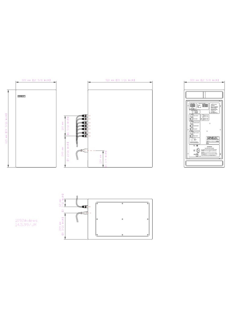
Dimensions: Height 615 mm
(24 3/16")
Width 320 mm
(12 5/8")
Depth 510 mm
(201/16")
HTHT
HTHT
HTS2S2
S2S2
S2 SYSTEMSYSTEM
SYSTEMSYSTEM
SYSTEM
SPECIFICATIONSSPECIFICATIONS
SPECIFICATIONSSPECIFICATIONS
SPECIFICATIONS
Crossover acoustical slope
Lowpass: 28 dB/octave
Highpass: 12 dB/octave
Midband rejection, freq. > 400 Hz: > 50 dB
Bass roll-off control operating
range in 2 dB steps: from 0 to -6 dB @ 33 Hz
Phase matching control in 90° steps: from 0° to -270° @ 120 Hz
CROSSOVERCROSSOVER
CROSSOVERCROSSOVER
CROSSOVER
SECTIONSECTION
SECTIONSECTION
SECTION
Short term amplifier output
power : 180 W (4 Ohm)
(Long term output power is limited
by driver unit protection circuitry.)
Amplifier system distortion
at nominal output:
THD < 0.08%
SMPTE-IM < 0.08%
CCIF-IM < 0.08%
DIM 100 < 0.08%
Signal to Noise ratio,
referred to full output: > 100 dB
Mains voltage: 100/200 or 115/
230V
Voltage operating range: ± 10%
Power consumption (average):
Idle 50 VA
Full output 300 VA
AMPLIFIERAMPLIFIER
AMPLIFIERAMPLIFIER
AMPLIFIER
SECTIONSECTION
SECTIONSECTION
SECTION
INPUTINPUT
INPUTINPUT
INPUT
SECTIONSECTION
SECTIONSECTION
SECTION
Input connectors: XLR balanced
RCA unbalanced
Input impedance: 10 kOhm
Input level for 100 dB SPL
output @ 1 m: variable from +6 to -6 dBu
Genelec Document DRHTS2001
COPYRIGHT GENELEC OY 1999
All data subject to change without prior notice
Note! All frequency response curves were measured in aNote! All frequency response curves were measured in a
Note! All frequency response curves were measured in aNote! All frequency response curves were measured in a
Note! All frequency response curves were measured in a
calibrated, 12 m cube, anechoic chamber at 1 m usingcalibrated, 12 m cube, anechoic chamber at 1 m using
calibrated, 12 m cube, anechoic chamber at 1 m usingcalibrated, 12 m cube, anechoic chamber at 1 m using
calibrated, 12 m cube, anechoic chamber at 1 m using
grade 1 measuring equipment. Input signal levels weregrade 1 measuring equipment. Input signal levels were
grade 1 measuring equipment. Input signal levels weregrade 1 measuring equipment. Input signal levels were
grade 1 measuring equipment. Input signal levels were
set at -20 dBu. The anechoic chamber error in the freeset at -20 dBu. The anechoic chamber error in the free
set at -20 dBu. The anechoic chamber error in the freeset at -20 dBu. The anechoic chamber error in the free
set at -20 dBu. The anechoic chamber error in the free
field response is less than 0.5 dB down to 60 Hz.field response is less than 0.5 dB down to 60 Hz.
field response is less than 0.5 dB down to 60 Hz.field response is less than 0.5 dB down to 60 Hz.
field response is less than 0.5 dB down to 60 Hz.
Genelec Oy, Olvitie 5Genelec Oy, Olvitie 5
Genelec Oy, Olvitie 5Genelec Oy, Olvitie 5
Genelec Oy, Olvitie 5
FIN - 74100 IISALMI, FINLANDFIN - 74100 IISALMI, FINLAND
FIN - 74100 IISALMI, FINLANDFIN - 74100 IISALMI, FINLAND
FIN - 74100 IISALMI, FINLAND
Phone:Phone:
Phone:Phone:
Phone: + 358 17 813311+ 358 17 813311
+ 358 17 813311+ 358 17 813311
+ 358 17 813311
Fax:Fax:
Fax:Fax:
Fax: + 358 17 812267+ 358 17 812267
+ 358 17 812267+ 358 17 812267
+ 358 17 812267
Email:Email:
Email:Email:
Web:Web:
Web:Web:
Web: www.genelec.comwww.genelec.com
www.genelec.comwww.genelec.com
www.genelec.com
Genelec Inc., 7 Tech CircleGenelec Inc., 7 Tech Circle
Genelec Inc., 7 Tech CircleGenelec Inc., 7 Tech Circle
Genelec Inc., 7 Tech Circle
NATICK, MA 01760, U.S.A.NATICK, MA 01760, U.S.A.
NATICK, MA 01760, U.S.A.NATICK, MA 01760, U.S.A.
NATICK, MA 01760, U.S.A.
Phone:Phone:
Phone:Phone:
Phone: +1 508 652 0900+1 508 652 0900
+1 508 652 0900+1 508 652 0900
+1 508 652 0900
Fax:Fax:
Fax:Fax:
Fax: +1 508 652 0909+1 508 652 0909
+1 508 652 0909+1 508 652 0909
+1 508 652 0909
Email:Email:
Email:Email:
Other Genelec Subwoofer manuals
Genelec
Genelec 7050B User manual
Genelec
Genelec 7360A User manual
Genelec
Genelec 7050B User manual

Genelec
Genelec 7050B User manual
Genelec
Genelec 7071A User guide
Genelec
Genelec 7060B User manual
Genelec
Genelec F Two User manual
Genelec
Genelec 7040A User manual
Genelec
Genelec 1094A User guide
Genelec
Genelec 7050A User manual

Genelec
Genelec 7050B User manual

Genelec
Genelec 5040A User manual
Genelec
Genelec 7073A User manual
Genelec
Genelec 7060B User manual

Genelec
Genelec 7360A User manual
Genelec
Genelec 7071A User manual
Genelec
Genelec 7370A User manual
Genelec
Genelec SAM 7300 Series User manual
Genelec
Genelec HTS4B User manual
Genelec
Genelec 7380A User manual
