Generac Power Systems MAC MIH400HC User manual

SAVE THIS MANUAL FOR FUTURE REFERENCE
MIH400HC
Indirect Fired Heat Cart
Owner’s Manual
MODEL NUMBER: _________________________
SERIAL NUMBER: _________________________
DATE PURCHASED:________________________
003999

ii Owner’s Manual for Indirect Fired Air Heater
(000004)
WARNING
California Proposition 65. Engine exhaust and some
of its constituents are known to the state of California
to cause cancer, birth defects, and other reproductive
harm.
(000005)
WARNING
California Proposition 65. This product contains or
emits chemicals known to the state of California to
cause cancer, birth defects, and other reproductive
harm.

Owner’s Manual for Indirect Fired Heater iii
Table of Contents
Section 1: Introduction and Safety
Introduction ..................................................................1
Read This Manual Thoroughly ....................................1
Safety Rules .................................................................1
How to Obtain Service .................................................1
General Hazards ...........................................................2
Explosion and Fire Hazards ........................................2
Trailer Hazards .............................................................3
Battery Hazards ............................................................3
Service Safety ..............................................................4
Section 2: General Information
Specifications ...............................................................5
External Component Locations ..................................6
Engine Component Locations ....................................7
Burner Component Locations ....................................8
Control Panel ................................................................9
Emissions Information ..............................................10
Engine Oil Recommendations ..................................10
Coolant Recommendation .........................................10
Fuel System ................................................................10
Cart Towing Guidelines .............................................10
Parking Brake Use .....................................................11
Frost Plug Heater .......................................................11
Burner .........................................................................11
Section 3: Operation
Theory of Operation ...................................................13
Before Starting Engine ..............................................13
Pre-start Checklist .....................................................13
Engine Oil Level Check .............................................13
Engine Coolant Check ...............................................13
Ducting Guidelines ....................................................14
Engine and Heater Startup ........................................14
General Overview ......................................................14
Operational Procedure ..............................................14
Engine and Heater Shutdown ...................................15
Emergency Stop .........................................................15
Thermostat .................................................................15
Changing Temperature Units ....................................15
View/Adjust Temperature Set Point ...........................16
Thermostat Control ....................................................16
Section 4: Maintenance
Maintenance ...............................................................17
Maintenance Tasks ....................................................17
Daily Walk Around Inspection ...................................17
Draining and Refilling the Oil .....................................17
Adding Coolant ..........................................................18
Maintenance Schedule ..............................................18
Maintenance Schedule ..............................................19
Battery Inspection ......................................................20
Battery Installation and Replacement ........................20
Other Maintenance Checks .......................................21
Short Term Storage ...................................................21
Return to Service .......................................................21
Section 5: Troubleshooting
General Troubleshooting Guide ...............................23
Section 6: Installation Diagrams and Service
Log
Control Box Wiring Diagram (1 of 3) ........................29
Service Log .................................................................32

iv Owner’s Manual for Indirect Fired Heater
This page intentionally left blank.

Owner’s Manual for Indirect Fired Heater 1
Introduction and Safety
Section 1: Introduction and Safety
Introduction
Thank you for purchasing a Generac Mobile Products
LLC product. This unit has been designed to provide
high-performance, efficient operation, and years of qual-
ity use when maintained properly.
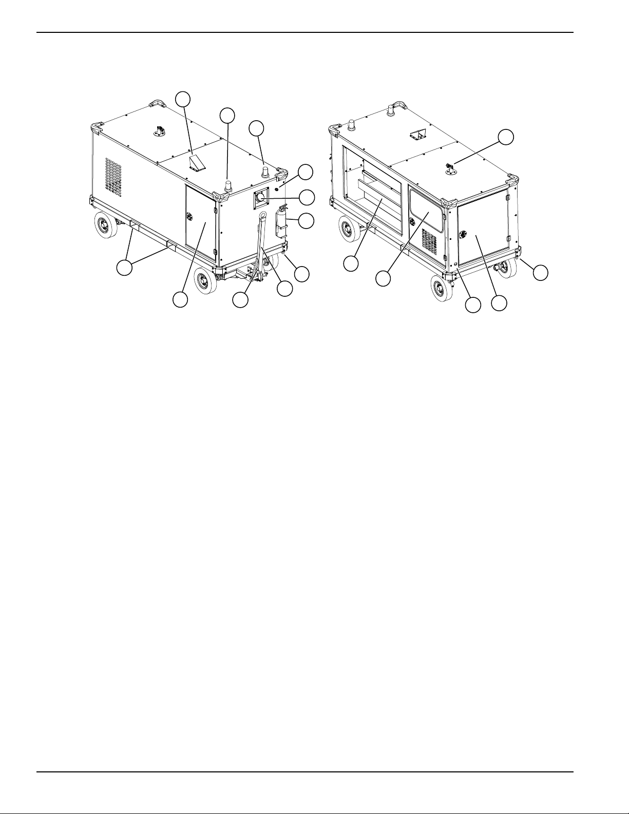
The MIH400HC indirect fired heat cart is designed and
built for sustained, reliable heat production in industrial
operating conditions and environments. The MIH400HC
is built to withstand frequent handling under these condi-
tions.
The unit has forklift access and chain attach points on
both sides. The fully enclosed design protects the operat-
ing components, allowing all-weather storage and opera-
tions.
The information in this manual is accurate based on
products produced at the time of publication. The manu-
facturer reserves the right to make technical updates,
corrections, and product revisions at any time without
notice.
Read This Manual Thoroughly
If any section of the manual is not understood, contact
your nearest Generac Mobile Products (GMP) Autho-
rized Service Dealer (ASD), or contact Generac Mobile
Products Customer Service at 800-926-9768, or visit
www.generacmobileproducts.com with any questions or
concerns.
The owner is responsible for proper maintenance and
safe use of the equipment.
SAVE THESE INSTRUCTIONS for future reference. This
manual contains important instructions for the unit that
should be followed during installation, operation, and
maintenance of the heater and batteries. ALWAYS sup-
ply this manual to any individual that will use this
machine.
Safety Rules
The manufacturer cannot anticipate every possible cir-
cumstance that might involve a hazard. The alerts in this
manual, and on tags and decals affixed to the unit, are
not all inclusive. If using a procedure, work method, or
operating technique that the manufacturer does not spe-
cifically recommend, verify that it is safe for others and
does not render the equipment unsafe.
Throughout this publication, and on tags and decals
affixed to the unit, DANGER, WARNING, CAUTION, and
NOTE blocks are used to alert personnel to special
instructions about a particular operation that may be
hazardous if performed incorrectly or carelessly. Observe
them carefully. Alert definitions are as follows:
NOTE: Notes contain additional information important to
a procedure and will be found within the regular text of
this manual.
These safety alerts cannot eliminate the hazards that
they indicate. Common sense and strict compliance with
the special instructions while performing the action or
service are essential to preventing accidents.
How to Obtain Service
When the unit requires servicing or repairs, contact a
GMP ASD for assistance. Service technicians are fac-
tory-trained and are capable of handling all service
needs. Go to https://www.generacmobileproducts.com/
parts-service/find-service for assistance locating a
dealer.
When contacting a GMP ASD about parts and service,
always supply the complete model and serial number of
the unit as given on its data decal located on the unit.
Record the model and serial numbers in the spaces pro-
vided on the inside front cover of this manual.
(000100a)
WARNING
Consult Manual. Read and understand manual
completely before using product. Failure to
completely understand manual and product
could result in death or serious injury.
(000001)
DANGER
Indicates a hazardous situation which, if not avoided,
will result in death or serious injury.
(000002)
WARNING
Indicates a hazardous situation which, if not avoided,
could result in death or serious injury.
(000003)
CAUTION
Indicates a hazardous situation which, if not avoided,
could result in minor or moderate injury.

2 Owner’s Manual for Indirect Fired Heater
Introduction and Safety
General Hazards
Explosion and Fire Hazards
Asphyxiation. Running engines produce
carbon monoxide, a colorless, odorless,
poisonous gas. Carbon monoxide, if not
avoided, will result in death or serious injury.
(000103)
DANGER
DANGER
Asphyxiation. Do not operate unit without
a properly functioning exhaust system.
Doing so will result in death or serious injury.
(000340)
WARNING
Do not operate this unit while transporting. Doing so
could result in death or serious injury.
(000231)
(000107)
WARNING
Hearing Loss. Hearing protection is
recommended when using this machine.
Failure to wear hearing protection could
result in permanant hearing loss.
(000111)
WARNING
Moving Parts. Keep clothing, hair, and
appendages away from moving parts. Failure
to do so could result in death or serious injury.
(000108)
WARNING
Hot Surfaces. When operating machine, do not
touch hot surfaces. Keep machine away from
combustibles during use. Hot surfaces could
result in severe burns or fire.
CAUTION
(000291)
Equipment damage. Do not attempt to start or operate
a unit in need of repair or scheduled maintenance.
Doing so could result in serious injury, death, or
equipment failure or damage.
WARNING
CAUTION
(000229)
Equipment or property damage. Do not block air
intake or restrict proper air flow. Doing so could
result in unsafe operation or damage to unit.
CAUTION
(000240a)
Unit damage. Do not stop engine before heating
unit is cooled. Doing so could result in unit damage.
CAUTION
(000246)
Equipment Damage. The emergency stop switch is
not to be used to power down the unit under normal
operating circumstances. Doing so will result in
equipment damage.
CAUTION
(000295)
Equipment damage. Shut down the heater before
turning off the generator. Failure to do so could
result in equipment damage.
(000105)
DANGER
Explosion and Fire. Fuel and vapors are
extremely flammable and explosive. Add fuel
in a well ventilated area. Keep fire and spark
away. Failure to do so will result in death
or serious injury.
(000143)
DANGER
Explosion and Fire. Fuel and vapors are extremely
flammable and explosive. Store fuel in a well
ventilated area. Keep fire and spark away. Failure
to do so will result in death or serious injury.
(000204)
DANGER
Explosion and Fire. Do not overfill fuel tank.
Overfilling may cause fuel to leak and ignite
or explode, resulting in death or serious injury.

Owner’s Manual for Indirect Fired Heater 3
Introduction and Safety
Trailer Hazards
Battery Hazards
Always recycle batteries in accordance with local laws and
regulations. Contact your local solid waste collection site or
recycling facility to obtain information on local recycling
processes. For more information on battery recycling, visit
the Battery Council International website at:
http://
batterycouncil.org
(000147)
WARNING
Risk of Fire. Unit must be positioned in a
manner that prevents combustible material
accumulation underneath. Failure to do so
could result in death or serious injury.
WARNING
Fire risk. Fuel and vapors are extremely
flammable. Do not operate indoors. Doing so
could result in death, serious injury, or
property or equipment damage. (000281)
WARNING
Explosion and fire risk. Do not smoke near unit.
Keep fire and spark away. Failure to do so could
result in death, serious injury, or property or
equipment damage. (000282)
WARNING
Crushing hazard. Verify parking brake is properly
secured and unit is on level ground. An unsecured
unit could suddenly roll or move, and could result in
death, serious injury, or equipment damage. (000352)
WARNING
Property or Equipment Damage. Tighten wheel lug
nuts every 30 days to factory specifications. Failure to
do so could result in death, serious injury, or property
or equipment damage. (000364)
WARNING
Control loss. Trailer must be securely coupled to the
hitch. An incorrectly coupled trailer could result in loss
of control, death, or serious injury.
(000360)
WARNING
Do not operate this unit while transporting. Doing so
could result in death or serious injury.
(000231)
(000137a)
WARNING
Explosion. Batteries emit explosive gases while charging.
Keep fire and spark away. Wear protective gear when
working with batteries. Failure to do so could result in
death or serious injury.
(000162)
WARNING
Explosion. Do not dispose of batteries in a fire. Batteries
are explosive. Electrolyte solution can cause burns and
blindness. If electrolyte contacts skin or eyes, flush with water
and seek immediate medical attention.
(000163a)
WARNING
Risk of burn. Do not open or mutilate batteries.
Batteries contain electrolyte solution which can
cause burns and blindness. If electrolyte contacts
skin or eyes, flush with water and seek immediate
medical attention.
(000130)
WARNING
Accidental Start-up. Disconnect the negative battery
cable, then the positive battery cable when working
on unit. Failure to do so could result in death
or serious injury.
WARNING
Environmental Hazard. Always recycle batteries at an
official recycling center in accordance with all local
laws and regulations. Failure to do so could result in
environmental damage, death or serious injury.
(000228)

4 Owner’s Manual for Indirect Fired Heater
Introduction and Safety
Service Safety
•DO NOT perform even routine service (oil/filter
changes, cleaning, etc.) unless all electrical com-
ponents are shut down.
•Replace all missing and hard to read decals.
Decals provide important operating instructions
and warn of dangers and hazards.
•Wear all task-appropriate PPE when completing
maintenance or service tasks.

Owner’s Manual for Indirect Fired Heater 5
General Information
Section 2: General Information
Specifications
Heater 400,000 BTU/hour (117.2 kW/hour) maximum
Type Indirect fired
Power ISUZU 3CE1 Tier 4 Final diesel, 23.4 HP (17.4 kW)
Operating Speed 1800 rpm
Engine Controls/Display LOFA, pushbutton
Air Volume 3600 CFM (6116 m3/hour)
Battery 575 CCA (115 CCA Reserve)
Static Pressure 9 in H2O (22.8 mm H2O)
Air Outlet 12 in (305 mm)
Electrical 12V
Engine Fuel Diesel
Engine Fuel Capacity 52 gal (197 L)
Engine Oil Capacity 7 qt (6.7 L)
Engine Coolant Capacity 2.1 qt (2.0 L)
Engine Fuel Rate (at 100% prime) 1.25 gph (4.76 Lph)
Burner Fuel Rate (at 100% prime) 3.39 gph (12.8 Lph)
Total Maximum Run Time 18 hrs
Temperature Rise 180 °F (82 °C)
Fan Class 22, RBA-909
Hitch Type Pintle ring
Tire Size 4 in x 8 in (10.2 cm x 20.3 cm)
Lug Nut Torque 100 ft-lbs (135.6 Nm)
Duct Length 25 ft (7.6 m)
Estimated Heater Efficiency 85%
Dimensions 168.5 in x 50 in x 72 in (427.9 cm x 127 cm x 182.9 cm)
Weight 4500 lbs (2041 kg) operating weight
Burner Riello R40 F10
Generator Marathon 282PSL1704

6 Owner’s Manual for Indirect Fired Heater
General Information
External Component Locations
Table 1 – External Components
A Bonnet I Parking brake
B Operating temp beacon J Burner/blower access door
C Low fuel warning beacon K Fork lift pockets
D Emergency stop L Exhaust
E Fuel fill M Engine access door
F Fire extinguisher N Engine block frost plug
G Tie down ring(s) O Control panel access
H Tow bar P Ducting shelf
004439
E
H
K
I
G
F
D
C
B
A
NM
G
L
J
O
P

Owner’s Manual for Indirect Fired Heater 7
General Information
Engine Component Locations
Table 2 – Engine Components
A Engine oil fill (not shown) G Engine oil dipstick
B Air cleaner assembly H Fuel/water separator assembly
C Coolant sub-tank (not shown) I Engine fuel pump
D Engine radiator cap J Electrical junction box
E Engine fuel filter K Generator
F Engine oil filter
K
J
C
I
E
GF
D
B
A
H

8 Owner’s Manual for Indirect Fired Heater
General Information
Burner Component Locations
Table 3 – Burner Components
A Blower fan and motor D Burner reset
B Fuel return valve E Fuel supply valve
C Burner fuel filter F Diesel fired burner
004084
FD
A
ECB

Owner’s Manual for Indirect Fired Heater 9
General Information
Control Panel
Table 4 – Control Panel Components
A Fuel gauge H Low temperature indicator lamp (red)
B Outlet temperature indicator I Burner stop button (red)
C Thermostat access J Temperature selection switch
D Battery disconnect K Main circuit breaker switch
E Engine ignition key L Panel lock
F Engine controller M Control box ID tag
G Burner start button (green)
ABCDE
GI
HJKLMF

10 Owner’s Manual for Indirect Fired Heater
General Information
Emissions Information
For emissions information, see the diesel engine OEM
manual.
Engine Oil Recommendations
Change oil and oil filter at least once every 12 months,
even if the hours of operation are fewer than the other-
wise recommended service interval. See the diesel
engine OEM manual for recommended oil types.
For more information, see the engine manual.
Coolant Recommendation
Use demineralized or distilled water for best results. Hard
water causes scale deposits, which reduces cooling effi-
ciency and raises internal temperatures, possibly leading
to engine damage.
Use a Long Life Coolant Antifreeze or Extended Life
Coolant that meets or exceeds these specifications:
•Isuzu Part Number 8-12346-290-0
•ASTM D4985
See the engine manual for recommended coolants.
Test coolant yearly, or every 1000 hours, whichever
comes first.
For more information, see the engine manual.
Fuel System
The heater is designed to operate with diesel fuel.
IMPORTANT NOTE: Comply with all laws regulating
the storage and handling of fuels.
Follow these guidelines:
•Use only ultra-low-sulfur diesel (ULSD) fuel.
•When temperatures are at or below freezing, use
No. 1D diesel fuel.
•When temperatures are above freezing, use No.
2D diesel fuel.
•In some areas of the country, climatized fuel—a
mixture of 1D and 2D—may also be used.
For more information, see the engine manual.
Cart Towing Guidelines
IMPORTANT NOTE: Do not exceed 15 mph (24 km/h).
The front axle is steered by a tow bar with a pintle ring
hitch. It is equipped with a mechanical parking brake
activated by raising the tow bar to the locked position.
NOTE: See the tow vehicle manual for coupling instruc-
tions.
Driving a vehicle with a cart in tow is vastly different than
driving the same vehicle without a cart in tow. Consider
the following:
•It takes longer to get up to speed.
•More room is need to turn.
•More distance is needed to stop.
•The driver is responsible for keeping the vehicle
and cart in control, and for all damage caused if
control is lost.
(000149)
DANGER
Risk of poisoning. Do not use mouth to siphon
coolant. Doing so will result in death or serious
injury.
CAUTION
(000323)
Engine damage. Use approved coolant only.
Failure to do so could result in equipment damage.
(000168)
DANGER
Explosion and Fire. Fuel and vapors are
extremely flammable and explosive. Keep fire
and spark away. Failure to do so will result
in death or serious injury.
(000204)
DANGER
Explosion and Fire. Do not overfill fuel tank.
Overfilling may cause fuel to leak and ignite
or explode, resulting in death or serious injury.
WARNING
Control loss. Trailer must be securely coupled to the
hitch. An incorrectly coupled trailer could result in loss
of control, death, or serious injury.
(000360)
WARNING
Property or Equipment Damage. Tighten wheel lug
nuts every 30 days to factory specifications. Failure to
do so could result in death, serious injury, or property
or equipment damage. (000364)

Owner’s Manual for Indirect Fired Heater 11
General Information
Before towing, verify the following:
•The coupling, tires, and wheels are in working
order.
•Wheel lug nuts are tightened to 100 ft-lbs (135.6
Nm).
While towing, make regular stops to verify the following:
•Coupler is secured to the hitch and locked.
•No damage or unusual wear to tire treads or side-
walls.
•Cart and doors are latched and secured.
Parking Brake Use
See Figure 2-1. Engage the parking brake by raising the
tow bar to the locked position. The locking lever (A) holds
the tow bar in place. Do not operate the unit without the
parking brake engaged.
Lift up the locking lever and slowly lower the tow bar to
disengage the parking brake. Do not attempt to move the
unit with the parking brake engaged; equipment damage
may occur.
Figure 2-1. Parking Brake Engaged
Frost Plug Heater
The unit is equipped with a frost plug heater (see
Table 1: External Components, letter N) to improve effi-
ciency in extreme temperatures. The frost plug heater
warms the battery blanket and oil pan before starting, to
improve starting and operation.
Burner
The burner runs on diesel fuel drawn from the fuel tank.
Unused fuel is returned to the fuel tank.
The burner reset button is located in the upper-center of
the burner cover. Press the burner reset button:
•If the burner control box indicates a fault.
•As part of annual maintenance.
For more information, see the burner manual.
WARNING
Crushing hazard. Verify parking brake is properly
secured and unit is on level ground. An unsecured
unit could suddenly roll or move, and could result in
death, serious injury, or equipment damage. (000352)
CAUTION
(000313)
Pinching and crushing hazard. To avoid
possible injury, keep fingers away from pivot
point when folding or unfolding trailer tongue.
003955b
A

12 Owner’s Manual for Indirect Fired Heater
General Information
This page intentionally left blank.

Owner’s Manual for Indirect Fired Heater 13
Operation
Section 3: Operation
Theory of Operation
The indirect heater generates heat if power is supplied to
the burner when the thermostat is on and reading tem-
perature. This starts the combustion in the blast box,
which heats up and moves hot air into the transition once
the burner fires up. Intake air molecules that are pushed
in from the fan come in contact with the stainless steel
tubes as the tubes heat up. This causes a transition in
temperature of the air molecules. The air is then pushed
past the thermostat couplers and into the air duct.
Before Starting Engine
Pre-start Checklist
•Remove all flammable materials and fire hazards
within 5 ft (1.5 m) of the unit.
•Keep the unit a minimum of 10 ft (3 m) from struc-
tures or barricades.
•Verify the unit is not leaking fluids: check inside
and outside the unit for leaking fuel, engine oil, and
engine coolant.
•Verify the following are clear of debris and obstruc-
tions:
– Engine air intake
– Engine exhaust stack
– Outlets and fan intakes
– Cabinet interior
– Burner cabinet interior
•Verify air duct hose is securely fastened to outlet
duct assembly.
•Inspect fuel, engine oil, and engine coolant levels.
•Verify unit is properly secure and level with the
parking brake engaged.
•Inspect the alternator drive belt for tension and
abnormalities.
•Verify the burner cover is securely installed.
•Inspect the generator. See the generator manual.
•Verify battery cable connections are not loose or
corroded.
•Inspect ducting for damage or unusual wear.
Engine Oil Level Check
NOTE: If engine was running, wait at least 10 minutes
before proceeding.
1. Remove oil dipstick and wipe it dry with a clean, lint
free cloth.
2. Slowly insert the clean oil dipstick into the oil dip-
stick tube. Verify the oil dipstick is fully seated.
3. After 10 seconds, remove the oil dipstick and look
at the oil level on both sides. The lower of the two
readings will be the correct oil level measurement.
4. Add oil (if necessary) to adjust the level. After add-
ing or changing the oil, run the engine for one min-
ute before checking the oil level. Wait 10 minutes
to allow the engine to cool and oil to fully drain into
the oil pan.
Typical causes of inaccurate oil level readings:
•Reading the high level of the oil dipstick.
•Reading the oil dipstick before the oil fully drains
into the oil pan.
•Inserting and removing the oil dipstick too quickly.
•Not fully seating oil dipstick in the oil dipstick tube.
Engine Coolant Check
Inspect the coolant sub-tank to check the coolant level.
Check the coolant level when the engine is cold, as cool-
ant flows to the sub-tank when the radiator is still hot,
which provides an inaccurate reading. Replace the cool-
ant according to the Maintenance Schedule, or if it is
contaminated or dirty. See Adding Coolant.
(000108)
WARNING
Hot Surfaces. When operating machine, do not
touch hot surfaces. Keep machine away from
combustibles during use. Hot surfaces could
result in severe burns or fire.
(000135)
CAUTION
Engine damage. Verify proper type and quantity of
engine oil prior to starting engine. Failure to do so
could result in engine damage.
(000154)
WARNING
Risk of burns. Do not open coolant system
until engine has completely cooled. Doing so
could result in serious injury.

14 Owner’s Manual for Indirect Fired Heater
Operation
Ducting Guidelines
•Place ducting in desired configuration before oper-
ating the unit.
•Tightly secure ducting ends to the unit and air craft.
•Avoid sharp bends or 90° turns in the ducting.
•Use only the necessary length of ducting required;
do not exceed maximum length.
•Verify that ducting is not in a high traffic area, and
will not impede workers or other machinery. Care
should be taken to prohibit the need to step or
climb over ducting.
•DO NOT place ducting over combustible materials.
•DO NOT place ducting over surfaces that may
damage it or reduce performance, such as water,
sharp rocks or glass, electrical wiring, piping, etc.
•DO NOT place or drape anything over ducting,
such as covers, insulation, blankets or cloth, elec-
trical wires, etc.
Engine and Heater Startup
General Overview
Heater and fan behavior are driven by several user-
defined benchmarks. The fan starts when the control box
breaker is on and the green pushbutton is pressed. The
high, medium, or low thermostat turns on based on the
setting of the control box dial.
Operational Procedure
NOTE: Verify the emergency stop is disengaged before
starting.
1. Raise tow bar to engage parking brake.
2. Rotate battery disconnect to ON.
3. Turn engine starter key to position 1.
The engine glow plug system engages. The glow
plug light will blink.
4. Once the glow plug light becomes steady, wait
approximately five seconds while fuel pump builds
pressure, then turn and hold engine starter key to
position 2until engine cranks and starts.
NOTE: Do not hold the engine starter key in the start
position for more than 15 seconds. Doing so will overheat
the starter motor. Wait 30 seconds for the starter motor to
cool before making a second attempt to start if the engine
fails to start.
5. Attach air ducting to aircraft, avoiding sharp bends
and twists in ducts.
IMPORTANT NOTE: A twisted or bent air duct will
cause loss of air pressure and temperature.
6. Turn main circuit breaker switch to ON.
7. Press green START button to engage burner and
fan motor.
8. Set thermostat selection switch to desired tem-
perature.
NOTE: The blue light on top of the unit will flash to indi-
cate low fuel level. The amber light indicates the unit has
reached operating temperature.
NOTE: Do not use starting aids, such as gasoline. Doing
so will damage the engine.
WARNING
Burn hazard. Do not remove ducting until all air
pressure has been emptied from hose duct.
Failure to do so could result in severe injury.
(000288)
(000108)
WARNING
Hot Surfaces. When operating machine, do not
touch hot surfaces. Keep machine away from
combustibles during use. Hot surfaces could
result in severe burns or fire.
WARNING
Crushing hazard. Verify parking brake is properly
secured and unit is on level ground. An unsecured
unit could suddenly roll or move, and could result in
death, serious injury, or equipment damage. (000352)
CAUTION
(000291)
Equipment damage. Do not attempt to start or operate
a unit in need of repair or scheduled maintenance.
Doing so could result in serious injury, death, or
equipment failure or damage.
WARNING
CAUTION
(000229)
Equipment or property damage. Do not block air
intake or restrict proper air flow. Doing so could
result in unsafe operation or damage to unit.

Owner’s Manual for Indirect Fired Heater 15
Operation
Engine and Heater Shutdown
1. Press red STOP button on control panel to stop the
burner.
NOTE: Burner will shut down and blower will keep run-
ning to cool the heat exchanger. STOP button will flash
until heat exchanger has cooled down.
2. After STOP button has stopped flashing, rotate
main circuit breaker switch to OFF.
3. Disconnect air ducting from aircraft and return it to
storage area.
IMPORTANT NOTE: Do not detach ducting until all
air pressure has been emptied from hose duct.
4. Rotate engine starter key to OFF.
5. Rotate main battery disconnect to OFF.
Emergency Stop
See Figure 3-1. The unit is equipped with an emergency
stop (A), located next to the fuel fill. The emergency stop
immediately shuts off the burner, fan motor, and engine.
To activate, push the button in. To deactivate, twist the
button until it pops out.
Figure 3-1. Emergency Stop
Thermostat
The thermostats are located behind an access panel
above the fuel gauge. Use the three thermostats to set
the high, medium, and low settings. Record the set tem-
peratures for future reference.
Figure 3-2. Thermostat Features
Changing Temperature Units
The thermostat is factory set to display temperature in
Fahrenheit (°F). Press the up and down buttons simulta-
neously to convert to Celsius (°C).
WARNING
In case of an emergency, press the emergency stop
button to stop the engine immediately. Failure to do
so could result in death or serious injury.
(000298)
CAUTION
(000295)
Equipment damage. Shut down the heater before
turning off the generator. Failure to do so could
result in equipment damage.
CAUTION
(000246)
Equipment Damage. The emergency stop switch is
not to be used to power down the unit under normal
operating circumstances. Doing so will result in
equipment damage.
A Temperature offset indicator
B Temperature units indicator
C Operating mode indicator
D Liquid Crystal Display (LCD)
E MENU button
F Output relay status indicator LED
G Down arrow button
H Up arrow button
004117
A
MENU
F
BIN
003820
E
B
A
C
D
F
G
H

16 Owner’s Manual for Indirect Fired Heater
Operation
View/Adjust Temperature Set Point
1. Press MENU and the set point will flash. Press
MENU again to display existing set point.
2. Press either UP or DOWN arrow keys to change
the temperature set point.
3. Press MENU to save the new value. The display
returns to sensed temperature.
4. Repeat steps 1–3 for each thermostat.
Thermostat Control
1. Press the MENU button and the display changes to
flashing SP.
2. Press the up or down buttons to reach desired
function.
3. Press the MENU button to display current value of
function.
4. Press the up or down buttons until desired value is
reached.
5. Press the MENU button to save. The display will
return to the sensor temperature.
NOTE: If the MENU button is not pressed after changing
the setpoint value, the new value will not be saved.
See Table 3-1 for all thermostat functions.
Table 3-1. Function Ranges and Settings
Function Range Factory
Setting
SP = Setpoint -30–212 °F
(-34–100 °C)
Low: 110
Medium: 130
High: 150
DIF = Differential 1 to 30 °F or °C 10
ASd = Anti-short
Cycle Delay 0 to 12 minutes 0
OFS = Tempera-
ture Offset 0 to 50 °F or °C 0
SF = Sensor
Failure Operation
0 = output
de-energized
1 = output
energized
0
Table of contents
Popular Outdoor Cart manuals by other brands

Great Little Trading
Great Little Trading Time for Tea Trolley quick start guide

TiCad
TiCad PRO quick start guide

YTL
YTL YTL22139-5 Instruction & assembly manual

New Star Computer Products
New Star Computer Products MED-M100 instruction manual

Gorilla Carts
Gorilla Carts GOR200-T owner's manual

Sound Cart
Sound Cart MiniCart Sound Cart manual