General Awnings Windsor User manual

Recommended Tools:
Before You Begin:
Saftey Glasses, Tape Measure, Carpenters Level, Framing Square, Hex Head Nut Drivers, Chalk Line,
Elec. Drill w/ Bits (Masonry Drill, Bits & Anchors may be required if securing to stone, concrete, or
any other masonry unit.), Small Screwdriver (to line up Roof Panels)
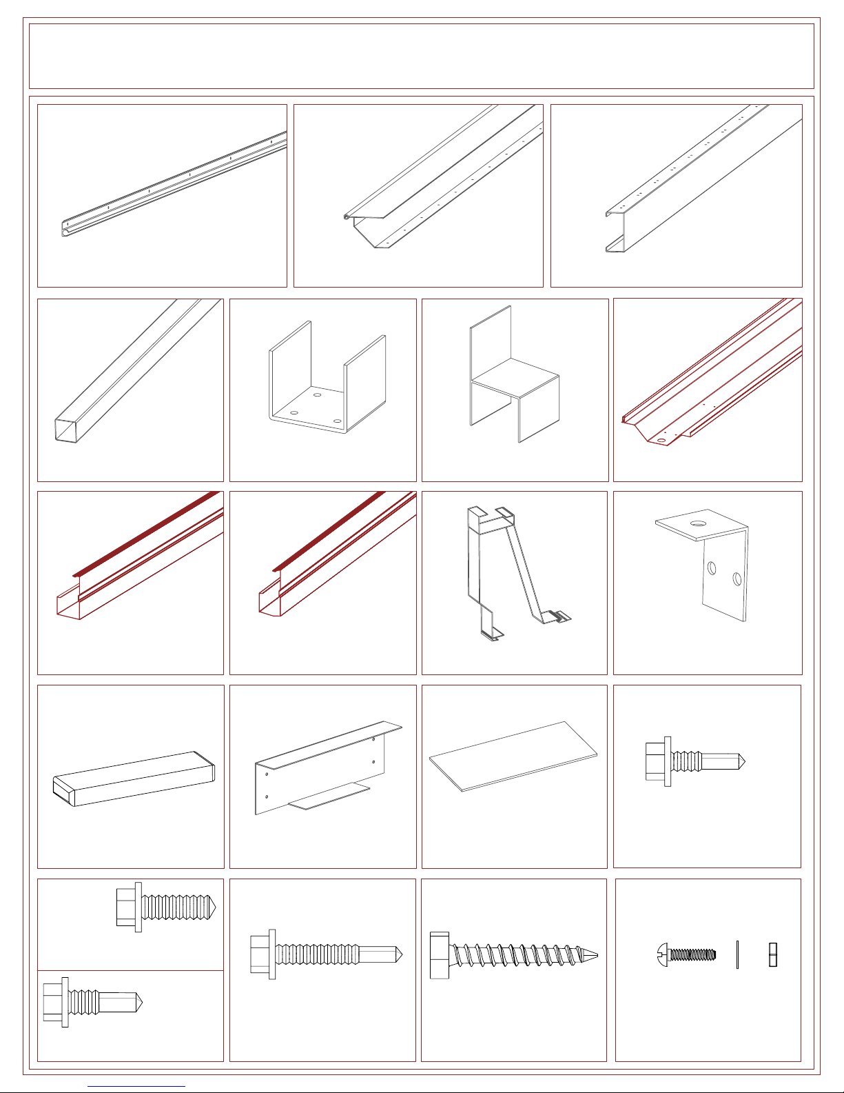
1.) Please read all instructions carefully. Check the Bill of Materials for any missing parts and gather
necessary tools. To prevent scratching of painted materials, place on a tarp, paper, or protective
material.
2.) You may be required to obtain a building permit for this structure from your local building authority.
This product should only be installed in 10, 20, or 30 psf (pounds per square foot) snow load and
90 mph or less wind speed zone (Custom models can be designed for heavier loads). This product
is listed under ICBO Evaluation Report #2621P. You may have to submit two copies of your plot
plan and also a copy of the evaluation report to your local building authority for a building permit.
Contact your local building department for details and your area's snow & wind loads.
3.) Note that this Kit is not designed to carry additional loads such as hanging heavy plants, swings,
people, or other objects.

1. Awning Rail 2. Wall Mounting Channel
14. Wall Channel Splice
Cover (optional)
(2-1/2" x 5-3/8" Plate)
7. Roof Panel
4. 3" Sq. Post
9. Front Fascia
w/ Styrofoam Plugs 10. Fascia Clip 11. Fascia Hanging Brkt.
(1" x 1-1/2")
12. Styrofoam Flashing Plug
3. C-Beam
15. Tek 2 x 3/4" Screw
17. Tek 5 x 1 1/4" Screw 18. 1/4" x 1 1/2" Lag Bolt
13. C-Beam Splice (optional)
(fits in 4" C-Beam)
16. Tek 3 x 3/4" Screw
16. Hex Head 3/4" Lag Screw
5. Lower Post Bracket
(appr. 2" tall, fits in 3" Post) 6. Upper Post Bracket
(appr. 4" tall, fits in 3" Post)
8. Projection Fascia
w/ Styrofoam Bird Plug
FOR C-BEAM
UNITS
FOR BOX BEAM
UNITS
(PANELS)
19. 1/2" Nut, Bolt & Washer
FOR MTG. RAILFOR MTG. RAILFOR POSTS

STEP 1
Fig. 1-1 Fig. 1-2
-Drill 1/4" holes in the Awning Rail 12" to 16" apart, or wherever stud is found. NOTE: Screws must hit solid wood.
-Slide the Awning Rail onto the Wall Mounting Channel before mounting to wall.
-Mark a level line approximately 5-1/2" above outswinging door (see Fig. 1-3).
-Apply a generous bead of silicone to the back of the Awning Rail.
-Fasten the Awning Rail and Wall Mounting Channel to the wall using 1/4" x 1 1/2" Lag Screws.
-If Wall Mount is in two or more sections, splice using the provided Wall Mounting Splice Plate. Apply silicone to the top of
the Wall Mounting Channel at splice and place the Wall Mounting Splice Plate over the splice. Attach with 4 - 3/4" Tek
Screws and remove excess silicone. (see Fig. 1-2)
-After the mounting channel is installed, apply caulk to the hinge to prevent water leaks.
Awning Rail
NOTE: Some installations may require special size and length screws
Fig. 1-3
12"-16"
1/4" Holes
Slideuntilflush
1/4" x 1-1/2"
Lag Screw
Wall Mounting Channel
Awning Rail
Apply silicone
between facets
Wall Mounting Channel
Wall Channel
Splice Cover
Awning Rail
Post height and
doors must be
taken into account
when mounting
Outswinging Door
Any door must be able
to open under unit
Unitmustslopedowntofront1/2"perProjectionFoot
Seeexamples
Post
12' Projecton = 6" Drop
10' Projecton = 5" Drop
8' Projecton = 4" Drop
Examples:
Recommend
minimum
of 5-1/2"
above door

Fig. 2-1 Fig. 2-4
STEP 2
Upper Post Bracket
Post
-Attach Upper Post Brackets to 3" Sq. Posts with 2 - Tek 5 x 1 1/4" Screws per side.
-Cut the post to proper height; we recommend front height of the cover should be 1/2" per foot of projection lower than
mounting height (see Fig. 1-3). REMEMBER TO subtract 4" from post height to allow for the C-Beam.
EX: Need 80" front height, cut post to 76". The 4" C-Beam will sit on top of the post.
-C-Beam (Open part faces away from house) sits in 3-1/2" from each end and sits back 6" from front, standard. Post spacing
should be no more than 10' between posts.
-Attach C-Beam to Upper Post Bracket with 4 - Tek 5 x 1 1/4" Screws.
-If C-Beam is in two or more pieces, splice as shown (Fig. 2-3, Fig. 2-4) using 4 - 3/4" Hex Washer Screws. Make sure to
place a post under the splice.
STEP 3
Fig. 3-1 Fig. 3-2
-Attach one Roof Panel to the first hole in the Wall Mounting Channel with 1/2" Bolt, Nut & Washer (see Fig. 3-1).
-Insert Styrofoam Flashing Plug (see Fig. 3-2).
Tek 5 x 1 1/4"
Screw
Fig. 2-3
Fig. 2-2
Back of C-Beam
Open Part of C-Beam
Back View
Front View
3" Sq. Post
3" Sq. Post
Post Bracket
C-Beam Splice
Back of
C-Beam
Post
Post Bracket
Awning Rail/Wall Mounting Channel Assembly
Roof Panel
1/2" Bolt, Nut & Washer,
Head on Top

Fig. 4-1
STEP 4
-Place a Roof Panel over the C-Beam and match the holes.
-Use Hex Head 3/4" Lag Screws to attach Roof Panels to the C-Beam through each hole.
-Slide or snap Roof Panels into place.
-After second or third Roof Panel is installed, check the front ends and make sure they are flush with each other;
keeping the Roof Panels flush in front will align the cover square with the structure.
STEP 5
Fig. 5-1
-Attach Lower Post Bracket to deck or slab using included 1 1/2" Lag Screws, 4 per Bracket. Use optional anchors for
concrete mounting. If mounting to concrete, a Lag Bolt Insert is required for each Lag Screw.
-Attach Lower Post Bracket to post with 2 - Tek 5 x 1 1/4" Screws per side.
IMPORTANT STEPS TO REMEMBER
-Bolt Roof Panel to Wall Mounting Channel first.
-Insert Flashing Plug
-Place first screw through Roof Panel and C-Beam.
-Slide or snap Roof Panels into position.
-Place second screw through first panel to C-Beam
and first screw in next panel to C-Beam.
-Keep Roof Panels flush.
Post
Bottom Post Bracket
Tek 5 x 1 1/4" Screw
Roof Panel,
Keep Flush

Fig. 6-1 Fig. 6-2
Fig. 6-4Fig. 6-3
Fig. 6-6Fig. 6-5
STEP 6
-Install a Fascia Clip on each Roof Panel as shown (see Fig. 6-1).
-Install the Front Fascia on the end with fabricated corner.
-Hook the top lip of the Front Fascia into the Fascia Clip slot (see Fig. 6-2).
-Let it hang loose.
-For the second piece of the Front Fascia, proceed to Fig. 6-3, or if only one piece, proceed to Fig. 6-4.
-(Fig. 6-3) For more than one piece of Front Fascia, caulk and fasten the pieces together using Tek 2 x 3/4" Screws.
Install second Front Fascia and continue.
-(Fig. 6-4) Start at one end and lock Front Fascia gutter lip between the bottom of the Roof Panel and the Fascia Clip.
-Make sure the Styrofoam Plugs were not removed from either end of the Front Fascia. Caulk the three sides of the face
nearest the fabricated corner to prevent sliding (see Fig. 6-6).
Fascia Clip
Roof Panel
Front Fascia
Roof Panel
Silicone bead
around edge
Front Fascia
Roof Panel
Fascia Clip
Fascia Clip
Front Fascia
Fascia Clip
Roof Panel
Styrofoam Plug
Caulk Edge
Styrofoam Plug

STEP 7
STEP 8
Fig. 7-1 Fig. 7-2
Fig. 8-1 Fig. 8-2
-Make sure the Styrofoam Bird Plug was not removed from one end of both Projection Fascias. Caulk around the inside face.
-Hold the rear end of the Projection Fascia approximately 12" away from the Wall Mounting Channel next to the house.
-Slip the front end of the Projection Fascia inside of the Front Fascia fabricated corner.
-Move the rear end of the Projection Fascia back to the Wall Mounting Channel.
-Place the flat top lip of the Projection Fascia on top of the Wall Mounting Channel.
-Screw the Front Fascia to the Projection Fascia using 4 - Tek 2 x 3/4" Screw.
-Screw the top lip of the Projection Fascia to the Wall Mounting Channel using Tek 2 x 3/4" Screw.
-From underneath, attach Fascia Hanging Bracket to bottom of Mounting Channel and side of Projection Fascia on both sides.
-Determine where you want water to run from the unit. Mark and drill several small holes in the bottom of the Front Fascia
forming a pattern no bigger than 2" x 3", or proceed to optional Downspout Assembly.
-Apply silicone to flange of Scupper & attach to Front Fascia with 2 - Tek 2 x 3/4" Screws covering the hole pattern (see Fig. 8-2).
Projection Fascia
Awning Rail/Wall Mounting Channel Assembly
Styrofoam
Bird Plug
Caulk
Around
Face
Front Fascia
Scupper
Fascia Hanging Bracket
Bottom Face
of Mounting
Channel
Side of Projection Fascia
Bottom of
Roof Pan
Front Fascia Projection Fascia
Post
Tek 2 x 3/4" Screw
Tek 2 x 3/4" Screw

CONGRATULATIONS! ASSEMBLY COMPLETED
Fig. D-1 Fig. D-2 Fig. D-3
Optional Downspout Assembly
-Cut a hole in the desired location in Front Fascia. Recommended in front of a post.
-Using 3/4" Tek 2 Screws, attach the downspout fitting over the hole in Front Fascia and caulk.
-Attach 2 - 45° elbows to the outlet.
-Cut the downspout to desired length.
-Attach and screw to the top 45° elbow
-Strap the tube to the post.
-Attach 90° elbow to the bottom of the tube.
Strap
Table of contents
Other General Awnings Accessories manuals
Popular Accessories manuals by other brands

HYDACELECTRONIC
HYDACELECTRONIC AquaSensor AS 3000 Operation manual

Life Fitness
Life Fitness M051-00K58-A034 installation instructions

Glastender
Glastender LP60 Operation manual

Ono Sokki
Ono Sokki GS-3813B instruction manual

Excell
Excell PW Service manual

Closet Maid
Closet Maid Indoor Furniture 1031 Assembling instructions