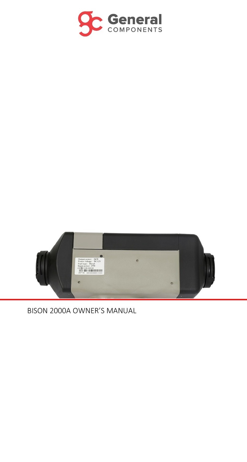
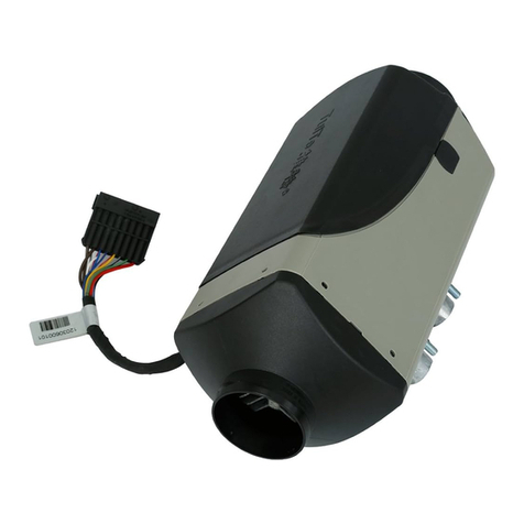
General Components BISON 4000A User manual

BISON 4000A OWNER’S MANUAL

Page 2 of 19
Contents
Uses and Applications................................................3
Safety Information.....................................................3
Technical Specifications.............................................4
Kit Contents ...............................................................4
Dimensions, mm ........................................................5
Installation.................................................................5
Installation: Angle......................................................6
Wiring Harness Connector Positions .........................6
Installation: Mounting ...............................................7
Installation: Mounting (Continued) ...........................8
Installation: Ducting and Pipework............................8
Installation: Ducting and Pipework (Continued)........9
Exhaust System..........................................................9
Combustion Air Intake...............................................9
Installation: Fuel Lines .............................................10
Installation: Fuel Line Connectors ...........................10
Installation: Fuel Line Length and Order .................11
Installation Fuel Pump Angle...................................11
Installation: Fuel Tank Head ....................................11
Installation: Fuel Tank (Continued) .........................12
Installation: Fuel Pick-up Tube ................................12
Electrical Components.............................................12
Analog Controller and Digital Timer ........................12
Controller Connections............................................13
Ambient Temperature Sensor .................................13
Electrical Diagram....................................................14
Operation: Analog Controller ..................................15
Operation: Digital Timer ..........................................15
Fault Codes ..............................................................18
Parts List ..................................................................19

Page 3 of 19
Preface
Thank you for purchasing the BISON 4000A diesel
heater (hereinafter referred to as ‘the heater’). This
manual will attempt to describe the structure,
working principle, installation and operation of the
heater. For future reference please keep this manual
in asafe and convenient place.
Uses and Applications
The heater works independently from the vehicle’s
engine, but is best fitted using the vehicle’s battery
and fuel tank. An auxiliary battery and/or fuel tank
can be used if necessary.
The heater will operate under normal conditions in
most vehicles from industrial and machinery sectors
to leisure craft like yachts and motor homes.
The heater is best used for heating various cabins and
compartments, engine preheating and glass
defrosting.
It is not recommended for constant long-term
operation for residential rooms, garages, holiday
homes etc.
Safety Information
Follow the installation guidelines carefully to ensure
the heater has the appropriate amount of clearance
between surfaces, so as not to become a fire hazard,
and that the various parts of the heater that get hot,
like the exhaust, are not exposed or contaminated by
possible fuel and oil.
Sufficient ventilation is required allowing proper air-
flow to the heater. If the heater is to be installed in a
box or compartment, please ensure an air vent is
installed for this reason. The air must also be fresh
and not contaminated by exhaust fumes or other
pollutants. Make sure that the air intakes and
exhaust do not get blocked by other objects.
Take care to ensure that the exhaust outlet is
installed in a way that prevents fumes from entering
the vehicle or are discharged in the direction of the
fresh air intake. Ensure the use of heat shields where
necessary to avoid fire damage.
If work is to be carried out on or around the heater,
turn it off at least an hour before so that it is cool
enough to be handled. If necessary, wear safety
gloves.
The fuel line must not be routed through the
passenger compartment or the driver’s cab in any
vehicle. Ensure that they are also installed so that the
exits are not at risk or in danger of becoming a
possible fire hazard.
Finally, take care and follow any and all precautions
when installing the heater to minimize injuries to
yourself and damage to the heater.
NOTE
This instruction booklet is subject to
revision without notice but the
instruction book is in conformity to the
purchased product.
The manual will attempt to answer any
and all questions the user may have. If
you have and further questions or find
anything incorrect within this manual,
please contact us directly.
Please check that the heater is not
damaged when first unpacking it and
contact the dealer immediately if any
problems are found.
If any problems or faults arise during
installation or operation, please contact
us directly or any other customer service
station authorized by our company. We
shall do our best to offer you our full
support.
NOTE
The most common faults that occur are
generally due to poor fuel quality, dirty (or
empty) fuel tanks or drops in voltage;
particularly in older vehicles like live aboard
narrowboats or used, commercial vehicles.

Page 4 of 19
Technical Specifications
Kit Contents
Heat Output Range
Minimum
Maximum
Heat Output: BTU/hr (kW/hr) 3071 (0.9) 13649 (4.0)
Diesel Fuel Consumption: U.S Gal./hr (L/hr) 0.03 (0.11) 0.13 (0.51)
Electric Power Consumption: Amps (Watts) 12 Volt DC 0.67 (8) 2.83 (40)
24 Volt DC 0.33 (8) 1.42 (40)
Voltage Operating Range: Volts DC 12 Volt DC 10.5 - 16 with Low and High Voltage Protection
24 Volt DC 21 - 32 with Low and High Voltage Protection
Operating Modes
Automatic Regulation - Adjustable 41°F to 95°F (5°C to 35°C)
Constant Heat Output Selection - Adjustable Min. to Max.
Air Circulation / Ventilation - No Heat, Fan Only
Dimensions: LxWxH, Inches (mm) 14.61 x 5.51 x 5.91 (371 x 140 x 150)
Weight: lbs (kg) 9.92 (4.5)
1
2
3
4
5
6
7
8
9
10
11
12
13
14
15
16
17
18
19
20
21
22
1. Main Heater Unit
2. Main Wire Harness
3. Control Switch / Timer
4. Fuel Pump
5. Fuel Pick-up Tube
6. Fuel Line
7. Fuel Line Connector Hose Clip
8. Fuel Line Connector
9. Fuel Pump Mounting Bracket
10. Anti-Vibration Mount
11. Air Intake Pipe
12. Exhaust Pipe
13. Air Intake Pipe Clamp
14. Exhaust Pipe Clamp
15. Air Intake Pipe Mounting Clamp
16. Exhaust Pipe Mounting Clamp
17. Grill
18. Outlet Cover
19. Ambient Temperature Sensor
(Optional)
20. Air Ducting Clamp
21. Air Ducting
22. Air Ducting Outlets
+
-

Page 5 of 19
Dimensions, mm
Installation
Figure I: Motorhome
1. In front of the passenger seat
2. Between driver’s and passenger’s seat
3. Under the vehicle’s floor
4. Under the rear seat
5. In rear trunk space
Figure II: Minivan
1. In front of the passenger seat
2. Between driver’s and passenger’s seat
3. Under the vehicle’s floor
4. Under the rear seat
5. In rear trunk space
30
130
90
376
25
24
133
55
7
75
105
44
17
80
150
325
140
B
A
A. Minimum clearance required for opening lid and dismantling glow pin and E.C.U.
B. Minimum clearance required for proper air intake.
1
2
3
4
5
1
2
3
4
5

Page 6 of 19
Figure III: Construction Equipment
1. In seat box
2. On rear wall
3. In a protective case outside
Figure IV: Truck
1.In passenger footwell
2. On cabin rear wall
3. In the toolbox
4. Under the bed
Installation: Angle
All positions suggested are examples. Other locations
are possible so long as they correspond to the proper
installation guidelines and requirements.
Figure V: Position Angles
1. Heater air intake
2. Glow pin position
3. Direction of air flow
Figure V shows the ideal installation position of the
heater; with exhaust pointing downward. Depending
on its location it can be tilted by 30° with the air flow
and hot air outlet facing the bottom. It can also be
tilted on its longitudinal axis by 90° so long as the
glow pin position points upward. During usual
operation the heater can deviate by 15° each way
with vehicle movement without impaired function of
the heater.
Wiring Harness Connector Positions
The main connector coming off the heater can be
moved to the other side of the heater if necessary. In
order to do so, you must first remove the air inlet grill
by twisting it so it’s clear of its securing lip and then
simply pulling it off. Next, remove the top cover by
lifting up the two front flaps near the air inlet. Be
1
2
3
1
2
3
4
1
1
2
3

Page 7 of 19
careful, as flaps are fragile and may break off easily.
You can then lift out the entire innards of the heater
(heat exchanger, fan motor, etc.) removing the cable
from the rubber securing bush and rerouting it
underneath the fan motor where it can then sit in the
cut-out on the opposite side. Ensure the rubber bush
is properly inserted and the heat exchanger is back
securely in position, then simply replace the lid and
grill back in position.
Installation: Mounting
The chosen mounting surface should be flat, and you
will need to drill the appropriate size hole for the
exhaust, combustion air inlet, fuel inlet and mounting
bolts. It is a good idea to mount the heater on the
supplied mounting bracket, particularly if the original
mounting surface is thinner than 1.5mm.
Figure VI: Mounting Gasket and Plate
A.Mounting Gasket
B. Mounting Plate
NOTE
Ensure the bottom cover fits correctly inside
the groove of the lid.
NOTE
The mounting plate shown in figure VI may
differ in overall size and the circular flange
may not be present, however the heater
footprint will remain the same.
A
B

Page 8 of 19
Installation: Mounting (Continued)
Figure VII: Mounting Positions
Above: Securing heater to the floor
Above: Securing heater to the wall
1. Ensure that the fan wheel spins freely and that
there is sufficient clearance between the heater and
the vehicle floor.
2. Ensure that the mounting surface is flat and
smooth.
3. The mounting gasket supplied must be fitted.
4. Mounting plate should be used to even out the
roughness of the surface.
5. M6 Washer
6. M6 Nut
Installation: Ducting and Pipework
1
2
3
1
4
5
6
1
2
3
4
5
6
1
2
3
4
3
5
6
Figure VIII: Ducting
1. Ducting and/or Grill
2. Main Heater Body
3. 90 mm Hose Clamp
4. 90 mm Air Ducting
5. 90 mmReducer
6. 90 mm Directional Vent
7. Heater’s Hot Air Outlet
8. 90 mm ‘Y’ Connector
7
3
6
6
8
4

Page 9 of 19
Installation: Ducting and Pipework (Continued)
Ducting can be installed as shown on the previous
page. Extra outlets can be installed to fit your own
needs however you should ideally not fit more than
the maximum of 3 outlets, to ensure you are
receiving sufficient hot air output.
Exhaust System
The flexible exhaust pipe can be shortened to no less
than 20cm and should not exceed a length of 1.2 m,
depending on the installation parameters. Route the
exhaust pipe from the heater to a suitable outlet,
ensuring that it is securely fitted to the heater using
the clamp supplied in the kit.
As the exhaust gets very hot during operation, it
should be installed in such a way that will not cause
damage to the vehicle. Ensure that it has sufficient
clearance of heat sensitive parts; paying close
attention to fuel lines (plastic and copper) and
electrical components. Make sure that the outlet
ends in open air and does not point in the direction
of travel. The whole system should also point
downwards and if necessary, a 5mm hole should be
drilled near the bottom to drain off any
condensation. You should also route the exhaust so
that the fumes are not taken back in by the air
intakes of the heater and ensure that the outlet does
not get clogged by snow, rock salt/sand, road debris
etc.
Figure IX: Air Intake and Exhaust
Combustion Air Intake
Like the exhaust pipe, the combustion air intake can
be shortened to up to 20 cm or lengthened to no
more than 1.2 m, again depending on installation
conditions. Some models can also be fitted with a
combustion air filter to prevent particles and debris
from entering the system.
NOTE
Do not work on the exhaust system unless
the heater has been switched off for over an
hour and wear safety gloves if necessary. All
types of combustion produce high
temperatures and toxic fumes and must be
installed in accordance to these instructions.
1
4
8
5
2
3
7
6
7
7
9
8
10
1. Heater Body
2. 25 mm Combustion Air Inlet
3. Combustion Air Intake Pipe Clamp
4. Combustion Air Intake Pipe
5. Air Filter OR End Cap
6. 24 mm Exhaust Outlet
7. Exhaust Clamp
8. Exhaust Pipe
9. Exhaust Muffler
10. Exhaust End Cap

Page 10 of 19
Installation: Fuel Lines
When working on or near any fuel lines or parts!
DO NOT
Smoke.
Use open flames.
Inhale fumes.
DO
Ensure the engine and heater are switched off
before attempting any and all work on the fuel
line installation or repair.
Cut any fuel line with a sharp knife to ensure a
clean cut free from crushes and burrs.
Ensure that the line going from the fuel pump to
the heater is on a gradual rise.
Ensure fuel lines are fastened safely to prevent
noise rattle and securely fitted to prevent any
damage.
Route fuel lines so that vehicle vibration and
movement will not have any lasting effects on
the service life.
Route the fuel line away from any and all heat
sources. Ensure adequate clearing from heat
sources if it cannot be avoided or use a suitable
heat shield.
Make sure all connectors are fastened securely
to prevent dripping of fuel, particularly onto hot
surfaces or electrical components.
Installation: Fuel Line Connectors
When connecting fuel lines into rubber connectors
always mount them flush and not on a bend to
prevent air bubbles from forming in the fuel line as
shown in Figure X.
Figure X: Fuel Connector Installation
Above: Improper Connection
Above: Proper Connection
1. Fuel Pump
2. Fuel Connector Clamp
3. Fuel Line Connector
Afuel filter must be fitted for all diesel heaters. Make
sure that it is installed the correct way according to
fuel flow as shown in figure XI.
Figure XI: Fuel Filter
NOTE
When installing, priming, repairing fuel lines
etc. there is always a risk of injuries due to
flammable and toxic sources. Take all the
necessary safety precautions when fitting
any fuel line or fuel line parts.
NOTE
Fuel filter, lines, connectors and clamps
should be replaced every 2 years.
1
3
2
2
1
3
2
2
1
2
1. Allowable Tilt Angle
2. Fuel Flow Direction

Page 11 of 19
Installation: Fuel Line Length and Order
Figure XII: Fuel Line Setup
Installation Fuel Pump Angle
Installation: Fuel Tank Head
See next page for legend…
1
3
2
4
5
6
7
8
9
1. Fuel Tank 6. Fuel Filter
2. Fuel Pick-up Tube 7. Fuel Pump
3. Fuel Connector Clamp 8. Fuel Pump Damper
4. Fuel Line 9. Heater Fuel Intake
5. Fuel Connector
A
B
A
A. Not Acceptable Position
B. Acceptable Position
1
2
3
A
B
C

Page 12 of 19
Installation: Fuel Tank (Continued)
1. Connection to heater body
2. Maximum fuel level
3. Minimum Fuel Level
Suction Height for Fuel Pump:
A. 3000 mm
B. 1000 mm (diesel), 500 mm (gasoline)
C. 2000 mm
Installation: Fuel Pick-up Tube
A fuel pick-up tube will need to be installed in the
vehicle’s fuel tank or an independent fuel tank
depending on what the installation calls for. Sealant
is not required to fit the pick-up tubes.
Depending on the pick-up tube provided in the kit,
you will need to install the pick-up tube in one of two
ways.
Pick-up Tube: Option 1 (GC0101)
To Install this type of Pick-up Tube:
Drill a hole in the top of the
vehicle’s fuel tank Φ22 ± 0.2mm in
size. Ensure it is smooth and clean
of burrs
Remove the top nut and washers
and bend the standpipe straight
Cut the standpipe down to size if
necessary
Fit the standpipe by tilting it into
position into the newly drilled
hole
Place the rubber and metal
washers back on top followed by
the nut and tighten it securely on
top
Pick-up Tube: Option 2 (GC0100)
To Install this type of Pick-up Tube:
If possible, remove the sender
unit from the vehicle’s fuel tank,
this will make it easier to attach
the nut securely back onto the
pick-up tube.
Drill a Φ6 ± 0.2mm hole into the
sender unit
Remove the nut from the pick-up
tube and feed it through the hole
ensuring the rubber ‘o’ ring
remains on the pick-up tube
‘head’ side
Replace the nut on the standpipe
to secure it safely to the sender
unit
Replace the sender unit into the
fuel tank.
The bottom of the fuel standpipe should be 30-40
mm from the bottom of the fuel tank to allow
enough suction of fuel and at the same time not
allow impurities and sediment to be drawn up the
standpipe.
Electrical Components
Make sure that all electrical components are
arranged in the vehicle so that they function correctly
under normal heater operations. Firstly, ensure that
no wires are damaged in any way and avoid feeding
them through areas that may cause damage to the
loom or cause kinking, jamming or exposure to heat.
If necessary, fit rubber grommets and plugs around
the loom in areas that are not waterproof or may get
damaged by road debris. Lastly make sure all
connections are free of corrosion and all firmly
connected.
Analog Controller and Digital Timer
To install the analog controller, simply remove the
rotary knob (it is quite stiff) and secure in a suitable
location with the screw provided, then replace the
knob back in the correct location.

Page 13 of 19
Alternatively, to fit the digital timer, simply fit the
appropriate screw inside the hole located at the
center of the timer. Both plug into the corresponding
black and clear plugs on the loom.
Controller Connections
The controllers are best installed in a manner that
they can be seen and operated easily to identify
working conditions and also for easy access. The
black and clear plugs connect to the corresponding
plugs on the loom (below). The remaining three-pin
socket on the timer or rheostat control plugs into the
remote control receiver if one is installed. An adaptor
cable may be necessary.
Digital Timer Connections
Analog Controller Connections
Wire Harness Connections
Ambient Temperature Sensor
The external temperature sensor plugs into the
corresponding blue and brown wired socket on the
diagram and should ideally by mounted at shoulder
height when sat down to ensure correct reading of
the air temperature. It should not be mounted in
such a way as to obstruct air flow; like up high, in the
corner of the vehicle cabin or above heat sources.
NOTE
Only one controller can be used at a time.
NOTE
Any surplus wires should be kept in good
condition and wrapped in electric tape to
avoid short circuiting.
UNUSED
BLUE/WHITE
BLUE
BLACK
BROWN
RED/YELLOW
GRAY
UNUSED
RED/WHITE
UNUSED
BLUE
BLACK
BROWN
RED/YELLOW
GRAY
RED
BLUE/WHITE
RED/WHITE
BLACK
BLUE
RED/YELLOW
BROWN
RED
GRAY

Page 14 of 19
Electrical Diagram

Page 15 of 19
Operation: Analog Controller
1. Variable Output Button and Indicator Light
2. Temperature Button and Indicator Light
3. Fan Only (Cold Air) Button and Indicator Light
4. Control Knob
5. Fixing Screw Hole (Located underneath control
knob)
The analog dial controller works by twisting the
control knob to the desired heat setting, and using
the buttons listed to determine the heater’s function.
Variable output is simply high to low heat. The
temperature button switches the heater to
thermostatic mode (the heater will then switch to a
cool-down cycle automatically once it has reached
the selected temperature). The fan button only
switches the fan on for cool air.
Operation: Digital Timer
See legend on top right of this page…
1. LCD Screen A. Days of the Week
2. Left Arrow Button B. Heating Symbol
3. Right Arrow Button C. Fan Symbol
4. Power/Back Button D. ‘P’ (Program) Symbol
5. OK Button E. Clock Symbol
6. Fixing Screw Hole F. Clock Face
Functions
Digital timer can be programmed for 3 different
start times daily on any combination of the 7
days of the week
7 step variable output mode
Thermostatic mode from 05°C to 35°C
Adjustable cold air fan mode
1
2
3
4
5
1
A
B
C
D
E
F
2
4
6
5
3

Page 16 of 19
Changing Language
The language should be set to English. However, if it
isn’t or the control has been reset to default settings
it will revert to Chinese. Please follow these steps to
convert the language to English.
1.Turn on the control with
the power button. Wait for
the symbols to stop flashing,
then press the power button
again.
2.Navigate to the clock face
symbol at the top of the
control by using the arrow
keys. When it is flashing
press both arrow keys
simultaneously.
3. P1 now appears.
4. Press OK and C1 will
appear
5. Keep pressing OK slowly
until ’02:oF’ appears.
6. Press and of the arrow
keys until the screen
reads ’02:on’.
7. Keep pressing OK until
back to the P1 menu screen.
8. Press power button to
return. The language will
now be set to English.
Changing Date and Time
1. To change the date and
time, navigate to the clock
symbol and press OK.
2. Select the current day of the
week using arrow keys and
press OK to confirm.
3. Select the hour using the
arrow keys and press OK to
confirm
4. Select minutes and press OK
to confirm.
5. Once completed, the control
will return to the home screen,
displaying correct time.
Manual On / Off
1. To turn the power on
manually, navigate to the
heating icon and press OK
2. The heater will start
automatically
3. Use the arrow keys to adjust
the output of the heater from
high to low (07 to 01
respectively)
4. To switch the heater off,
press the heater button to
return to the home screen.
NOTE
Disconnecting timer
from the harness
resets the date and
time.

Page 17 of 19
Switching to Thermostatic Mode
To switch the heater to
thermostatic mode, turn the
heater on manually, as
discussed in previous section.
1. Once the heater is on, press
and hold the OK button for
three seconds and then release
it.
2. The display will change to a
temperature setting, which can
be adjusted from 05oC to 35 oC
using the arrow keys.
3. To adjust back to the variable
output mode, press and hold
the OK button again for 3
seconds and then release it.
4. To switch the heater off, press the power button to
return to the home screen.
Fan Mode
The fan mode works in the same way as the manual
on/off mode. Simply navigate across to the fan
symbol and confirm with OK. The fan will then
automatically switch on and its speed can be
adjusted from high to low (07 to 01 respectively)
using the arrow keys. To switch it off, press the
power button.
Programming Heater Start Times
The digital timer can be programmed for three
individual start times per day on any combination of
seven days.
1. Navigate to ‘P’ symbol and
press OK
2. Using the arrow keys, select
the number ‘1’ (flashing) and the
top of the screen and press OK –
number ‘1’ is the first preset
heater start time.
3. Using the arrow keys, select
‘ON’, as this will allow the heater
to switch on after the presetting
is complete.
4. Select the length of time you
want the heater to run by using
the arrow keys. L800 represents
800 minutes. Run time can be set
to 50 to 990. Press OK to
confirm.
5. Select the hour you wish the
heater to start using the arrow
keys and then pressing OK to
confirm.
6. Select minutes in same
manner and press OK to confirm.
7. Select the days of the week
you want your start time ‘1’ to
initiate. Use arrow keys to scroll
down the week days and OK key
to select ‘ON’.
8. Preset start time ‘1’ is now set,
as indicated by underlining
number ‘1’ on the display.
9. Set start times ‘2’ and ‘3’
following steps 2 – 7 above.
NOTE
To turn any of the preset times off without
altering set times, repeat step ‘3’ above and
select ‘OFF’ using arrow keys. Then
repeatedly press OK until you return to home
screen.

Page 18 of 19
Fuel Line Priming Feature
ATTENTION:
Not to be used during normal heater operation.
Disconnect the fuel line from the heater to prevent
flooding of the heater with fuel and place it in a
suitable receptacle.
1. To enter the fuel priming
mode, navigate to the clock face
symbol using the arrow keys and
press both arrow keys
simultaneously.
2. P1 will appear on the screen.
3. Select P2 using any arrow key
and press OK to confirm.
4. The fuel pump will begin to
rapidly pump the fuel.
5. It will automatically shut
down after three minutes. You
an alternatively press any key to
stop the pumping at any time
and return to home screen.
Resetting Timer to Factory Settings
1. Navigate to the clock face
symbol of the menu and
simultaneously press both arrow
keys.
2. P1 will appear on the screen.
3. Using left arrow key select
‘01’ and press OK to confirm.
4. The Digital Timer will now be
reset to its default factory
settings.
Fault Codes
Analog Controller
When the ECU had discovered a fault, the analog
controller will flash a fault code. The controller
should therefore be ideally placed where it can be
clearly seen and accessed.
The faults will be displayed as short flashes followed
by long flashes. To determine the code, you must
count the number of long flashes.
Flash
Count
Cause
1
Failure of second start
3
Termination of third time of combustion
3
Voltage power out of specified range
4
Glow pin temperature increases slowly
5
N/A - Air Heater will not flash 5 times
6
Temp. Sensor: broken circuit or short circuit
7
Fuel Pump: broken circuit or short circuit
8
Fan Motor: broken circuit or short circuit
9
Glow Pin: broken circuit or short circuit
10
Overheat
11
Overheat Sensor: broken circuit or short circuit
12
Controller: broken circuit or short circuit
Digital Timer
The digital timer will display the fault code on its LCD
monitor.
Code
Cause
1E-02
Overheat - Check for obstruction or damaged
ducting.
1E-10
Ignition failure - Check fuel supply, blocked
supply or fuel pump
1E-30
Voltage too high
1E-31
Voltage too low - check battery or voltage drop
in supply cable
1E-52
Overheat sensor failure
1E-70
Fuel Pump open circuit or ECU failure
1E-80
Fan Motor failure
1E-90
Glow Pin Failure
1E-d3
Maintenance reminder

Page 19 of 19
Parts List
GC0095
L-Shaped Mounting Plate
GC0168
Self-Tapping Screw
GC0361
Self-Drilling and Self-Tapping Screw
GC0555
Thru Hull Fitting, 22 mm
GC0556
Thru Hull Fitting, 24 mm
GC0360
Self-Drilling and Self-Tapping Screw
GC0422
Nylon Zip Ties, 200 mm Length
GC0357
Self-Tapping Screw
GC0363
Nut
GC0285
Blower Motor Support Bracket
GC0291
Sensor Clip
GC0192
Protection Pad for Analog Controller
GC0252
Base Gasket
GC0088
Air Duct Connector, 60 mm to 90mm
GC0294
Inlet Grill
GC0085
Air Outlet, 90 mm
GC0087
T-Joint, 90 mm
GC0090
Straight Connector, 90 mm
GC0092
Ducting Hose Clip, 90-100 mm
GC0094
L-shaped Elbow, 90 mm
GC0630
Air Ducting, 90 mm
GC0174
Combustion Air Hose Clip, 24 mm
GC0193
Combustion Air Pipe
GC0232
Burner Gasket
GC0283
Casing for Blower Motor
GC0284
Wheel for Blower Motor Assembly
GC0286
Heat Exchanger
GC0287
Burner
GC0296
Wheel for Blower Motor Assembly
GC0510
Motor Gasket
GC0223
Glow Pin, 24V
GC0231
Glow Pin Screen
GC0292
Top Cover
GC0293
Heater Lower Casing
GC0295
Outer Hood
GC0334
Fuse
GC0335
Fuse
GC0611
Analog Control
GC0653
Digital Control Switch
GC0654
Digital Control Switch
GC0695
Analog Controller with GSM Receiver
GC0097-
03
External Temperature Sensor
GC0277
Controller, 12V
GC0278
Controller, 24V
GC0281
Blower Motor, 12V
GC0282
Blower Motor, 24V
GC0183
Wire Harness
GC0222
Glow Pin, 12V
GC0233
Overheat Sensor
GC0173
Exhaust Pipe P-clip
GC0113
Exhaust Pipe
GC0199
Exhaust Pipe P-clip
GC0207
Flange Seal Exhaust
GC0075
Fuel Tank, 5L, Metal
GC0076
Fuel Tank, 10L, Plastic
GC0122
Fuel Line Connector, 5 mm, 50 mm Length (Diesel)
GC0162
Fuel Pump Mounting P-clip, 34 mm
GC0163 Fuel Line Connection Tee, 8 x 8 x 6 mm
GC0187
Inline Fuel Filter
GC0427
Fuel Line Connector, 3.5 mm, 50 mm Length (Gasoline)
GC0500
Fuel Pump Damper
GC0101
Fuel Pick-up Tube
GC0158 Fuel Pipe Clamp, 11 mm
GC0160
Fuel Pipe Clamp, 14 mm
GC0132
Fuel pump, 12V
GC0182
Fuel pump, 24V
GC0204
Fuel Pipe Clamp, 10 mm
GC0197 Fuel Pipe Connection Tee
GC0609
Fuel Pipe, 1.5 mm, 1.2 M Length
GC0610
Fuel Pipe, 1.5 mm, 4 M Length
For pictures and further descriptions of each part,
please visit www.generalcomponents.ca
Table of contents
Other General Components Heater manuals
Popular Heater manuals by other brands

Protemp
Protemp PT-80-OFR User's manual & operating instructions

STIEBEL ELTRON
STIEBEL ELTRON CWM 500 P Operation and installation instruction

Toyotomi
Toyotomi Kerosun LC-3000 operating manual

KALOS
KALOS KLEH122 Assembly instructions

Toyotomi
Toyotomi KS-27A Operation and maintenance instructions

GET
GET GFHT2 instruction manual