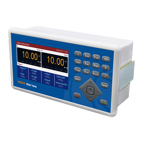
General Measure GM9907 Series User manual

GM9907-L5
User’s Manual
110608060003
V 0 1 . 0 2 . 0 2

©2020,Shenzhen General Measure Technology Co., Ltd. All rights
reserved.
Without Shenzhen General Measure Technology Co., Ltd.’s
permission, any company or person have no responsibility to copy,
transmit, transcribe or translate to any language version.
Our company's products are under continually improvement
and updating so we reserved the right to modify this manual at any
time without notice. For this reason, please visit our website
regularly to update newest information.
Company Website http:// www.gmweighing.com
Product Performance Standards: GB/T 7724—2008

Contents
1. Outline..........................................................................................................................- 1 -
1.1 Functions and Features....................................................................................... - 1 -
1.2 Front Panel Description...................................................................................... - 1 -
1.3 Rear Panel Description........................................................................................- 3 -
1.4 Technical Specifications.......................................................................................- 3 -
1.4.1 General specifications........................................................................................- 3 -
1.4.2 Analog part..................................................................................................- 3 -
1.4.3 Digital part.................................................................................................. - 4 -
2. Installation....................................................................................................................- 5 -
2.1 General principle................................................................................................. - 5 -
2.2 Load Cell Connection.......................................................................................... - 5 -
2.3 I/O Function Connection....................................................................................... - 5 -
2.4 Power Supply Connection..................................................................................... - 6 -
2.5 Serial Port Connection........................................................................................... - 7 -
2.6 Touch Screen Calibration.......................................................................................- 7 -
3. User Permission Description....................................................................................... - 9 -
4. Menu.......................................................................................................................... - 10 -
4.1 Recipe parameter..................................................................................................- 11 -
4.2 Weight parameter................................................................................................. - 14 -
4.3 Calibration............................................................................................................- 15 -
4.4 COM Para............................................................................................................ - 17 -
4.4.1S Continuous Send Mode.......................................................................... - 18 -
4.4.2 Response Mode-1..................................................................................... - 19 -
4.4.3Response Mode-2...................................................................................... - 21 -
4.4.4Response Mode-3...................................................................................... - 21 -
4.4.5 Printing.................................................................................................... - 22 -
4.4.6 Modbus-RTU Protocol............................................................................. - 24 -
4.4.7 Ethernet communication...........................................................................- 42 -
4.5 I/O Function......................................................................................................... - 43 -
4.5.1 Output, input port definition.................................................................- 43 -
4.5.2 IO test....................................................................................................... - 47 -
4.6 Statistics............................................................................................................... - 48 -
4.7Motor Para.............................................................................................................- 49 -
4.7.1 Motor drive feed description.................................................................... - 51 -
4.7.2 Motor drive discharge process description...............................................- 51 -

4.8 Maintenance.........................................................................................................- 52 -
5. Flowrate Function...................................................................................................... - 55 -
5.1 Real-time Flowrate...............................................................................................- 55 -
5.2 Expected Flowrate Function Description............................................................ - 56 -
5.3 Supplement Control............................................................................................. - 57 -
5.3.1 Triple supplement..................................................................................... - 57 -
5.3.2 Double supplement................................................................................... - 57 -
5.3.3 Single supplement.....................................................................................- 58 -
5.4 U disk update software........................................................................................ - 58 -
5.4.1 Upgrade steps............................................................................................- 58 -
5.4.2 Background upgrade steps........................................................................- 58 -
5.5 U disk upgrade boot interface..............................................................................- 58 -
6. Bulk ACUM process..................................................................................................- 60 -
7. Dimension(mm)......................................................................................................... - 63 -

GM9907-L5 bulk scale controller user’s manual
- 1 -
1. Outline
GM9907-L5 bulk scale controller is a weighing control instrument specially
developed for discontinuous automatic accumulation scale. The controller adopts a full
English touchscreen display interface, has the characteristics of moderate size, high
precision, powerful function and simple and practical operation.It can be widely used in
chemical industry, grain, port and other industries that need bulk metering equipment.
1.1 Functions and Features
Full English touchscreen display interface, make the operation more intuitive and
simple
28 I/O Function input and output control (12 in /16 out); input and output port
location can be customized.
I/O Function test function,convenient controller debugging
20 recipes can be stored for different weighing capacity,convenient for different
range of material packaging.
Convenient USB port to input and output of historical data.
Fill control functions, convenient bulk scale with the front filling device of control
connection.
Multiple digital filtering function
Automatic zero tracking function
Time / date function
3 level user permission setting
Dual serial ports to connect with printer, computer, Secondary display.
Single ethernet communication function, easy to communicate with the upper
computer
1.2 Front Panel Description

GM9907-L5 bulk scale controller user’s manual
- 2 -
Interface Description:
User info: Show user ID, system time, recipe ID, target value, total ACUM and batch.
Weight status: Weight value display, weight unit display, Status display and shortcut
I/O Function.
Packaging info:Display current target flowrate, total stock in and out volume and
ACUM data etc.
Function parameters:Controller menu parameter and setting.

GM9907-L5 bulk scale controller user’s manual
- 3 -
Debug interface description:
Shortcut setting recipe paremeter: Can promptly setting recipe parameter, debug
controller easliy.
Packing history record: Can view the current packaging history data directly, easy
to compare.
1.3 Rear Panel Description
1.4 Technical Specifications
1.4.1 General specifications
Power supply:DC2 4V
Power filter: Included
Operating temperature:-10 ~4 0 ℃
Maximum humidity: 90% RH without dew
Power consumption: about 15 W
Dimensions::190mm ×124mm ×48mm
1.4.2 Analog part
Load cell power supply:DC 5 V 1 25 m A (MA X )

GM9907-L5 bulk scale controller user’s manual
- 4 -
Input impedance:10 M Ω
Zero adjustment range:0 .00 2 ~15 .6 25 m V (when load cell is 3mV/V)
Input sensitivity:0 . 0 2 u V / d
Input range:0 . 0 0 2 ~1 5 . 6 2 5 m V
Conversion:S igm a - Del ta
A/D Conversion rate:12 0 、24 0 、48 0 、960 Times/second
Non-linear:0.01% F.S
Gain drift:10PPM/℃
The maximum display accuracy:1/100000
1.4.3 Digital part
Display: 7-inch resistance touch screen
Negative display: "—"
Overload Indication:"Over Capacity / Loadcell Input Under"
Decimal point position: 5 options

GM9907-L5 bulk scale controller user’s manual
- 5 -
2. Installation
2.1 General principle
1)Make appropriate installation holes on the control box, ( size: 179(±1)mm ×113(±1)
mm)
2)Install the GM9907-L5 into a control box
3)Remove the fixing plates on both sides of GM9907-L5, fix it with the fixing plates and
lock them with M3*10 screws.
2.2 Load Cell Connection
GM 9907- L 5 bulk scale controller can connect resistance strain bridge sensor.
When chose the six-wired load cells, must bridge the SN+ with EX+ and bridge the SN-
with EX-
EX+:Excitation+ EX-:Excitation- SN+:Sense+ SN-:Sense- SIG+:Signal+ SIG-:Signal-
2.3 I/O Function Connection
GM 9907- L 5 bulk scale controller controls 28 lines I/O (12 input and 16 output).
It uses optoelectronic isolation technology to transfer data. The I/O signal input is low level
effective, and the output is open-collector mode. The driving current can reach 500mA and
the full load current is up to 3A, and Terminal connection is shown as below:

GM9907-L5 bulk scale controller user’s manual
- 6 -
I/O Function Input port diagram
I/O Function output connection diagram
I/O Function value of GM9 9 0 7-L5 is user-defined to facilitate wiring and some
special applications. Please refer to section 4.5
2.4 Power Supply Connection
GM9907- L 5 bulk scale controller use 24V DC power supply. The connection is
shown in the figure below:
Power terminal diagram
24V+ connect DC+,24V-connect DC-.
Note:this product use 24V DC power
supply,use 220V AC power supply will
permanently damage the controller and
cause danger.

GM9907-L5 bulk scale controller user’s manual
- 7 -
2.5 Serial Port Connection
GM9907-L5 can provide two serial ports. It is depicted below.One for RS-232(Port
TXD、RXD、GND);the other is RS-485,(Port A、B、GND).serial ports support:
MODBUS mode,Cont mode,Command mode and Print.
Controller and computer connection diagram:
Connection between GM9907-L5 and a host computer (RS-232):
Connection between GM9907-L5 and a Host Computer(RS-485)
2.6 Touch Screen Calibration
Fisrt use new controller or laid-aside for a long time need to calibrate touch screen,
calibrate instruction:
GM9907-L5 power on, long press any point on the touch screen at the same time,

GM9907-L5 bulk scale controller user’s manual
- 8 -
system turn to touch screen calibrate interface, long press cursor position on touch screen,
cursor position calibrate finish, after the interface displays the coordinates of this point,
enter to next calibrate automatically. Follow cursor position changes long press accordingly,
calibrate finish, and interface show 5 calibration point coordinates, enter to main interface
automatically. If enter the calibration interface of the touch screen by mistake, press the
"cancel" button in the lower right corner to exit the interface.

GM9907-L5 bulk scale controller user’s manual
- 9 -
3. User Permission Description
In order to prevent wrong operation causing GM9907-L5 working improperly, it
provides three rights (operators, administrators and system administrators) :System
administrator can perform all operations (not open to users). The operator and administrator
rights restrictions are as follows:
Permission
Operation
Operator
Can check all the parameters.
Can set Quantitative parameter and I/O Function test.
Can export and clear the history record.
Administrator
All operator privileges are available.
Can calibration, I/O Function define, set over/under value and set stock-in
and stock-out mode.
Permission description:
Controller default operator log on.
Swift permission, can click the parameter item that needs permission, and enter
the password of the corresponding administrator(password :0000) or system
administrator in the pop-up box to log in successfully.
Click the parameter item that needs permission, and the current user's password
can be modified in the pop-up box.
In the【Display Style】parameter of 【Maintenance】, set the permission exit time,
which is used to limit the login duration of administrators and system
administrators. When the permission exit time reaches, the privileges of the
current administrator or system administrator will be returned to the operator
privileges.
In the【Display Style】parameter of 【Maintenance】,Multi-user login function can
be enabled to set the number of users to log in. Users can be selected to log in
when power on

GM9907-L5 bulk scale controller user’s manual
- 10 -
4. Menu
Click menu, can check and modify the parameters
Under the menu interface, can check the version information of the controller
software and scan the QR code on the right to download user’s manual.
Click the upper left corner to exit the current interface and return to the higher
interface

GM9907-L5 bulk scale controller user’s manual
- 11 -
4.1 Recipe parameter
In【Home】interface press recipe parameter, display recipe interface:
Can switch recipe ID at left side.
Click sub option button at right side, enter correspond interface, set parameter
information.
Click upper left corner, esc current interface back to superior interface.
Recipe
Parameter
Description
Filling
values
Used to set bagging weight value relevant parameters
Target value
Target value. Initial value:0; range: 0~full scale
Co-Fi
Remain
In quantitative process, if the weighing value ≥ target value –
Coarse Flow leading quantity, closing Coarse Flow fill. Initial
value:0; range: 0~full scale
Free Fall
In quantitative process, if the weighing value ≥target - free
fall value, closing Fine Flow.
Initial value:0; range: 0~full scale

GM9907-L5 bulk scale controller user’s manual
- 12 -
Near Zero
Band
When in the process of discharging,if weight≤Near Zero,
then start the discharge delay timer.
Initial value:0; range: 0~full scale
Filling
Times
Used to set time - related delay timer parameters in the feeding process
Filling
PreDelay
Timer
When the quantification process starts,after the delay time, the
controller will stable and zeroing (if it does not meet the Zero
Interval condition, it will not stable and not zeroing), and then
start the filling process;
Initial value:0.5;range:0.0~99.9 (Unit:s)
Result
Waiting
Timer
After the fine filling is turned off (or the Over/Under is turned
on, the Over/Under alarm is finished), quantification process
is started. After the holding time is passed , need to judge the
stability and record the current weight ,then enter the
Over/Under check process.If the Over/Under is turned off ,
the quantification process is finished, enter to next process.
Initial value:1.0;range:0.0~99.9 (Unit:s)
DISC Delay
Timer
During the discharge process, when the weight value of the
weighing hopper is less than the Near Zero Band, the delay is
started, when delay time is finished, discharge signal is
closed.
Initial value: 0.5; Range: 0.0~99.9. (Unit: s)
COMP.
Inhibit
Timer(Co-F)
When the quantification process starts, during this time, in
order to avoid overshoot, no weight judgment is made, coarse
filling is always valid. Initial value: 0.9;
Range: 0.0~99.9. (Unit: s )
COMP.
Inhibit
Timer(Fi-F)
After coarse filling is finished, during this time, in order to
avoid overshoot no weight judgment is made, fine filling is
always valid. Initial value: 0.9; Range: 0.0~99.9. (Unit: s)
Initial value:0.9;range:0.0~99.9 (Unit:s)
Over/Under
Used to set parameters related to Over/Under,alarm reminder, etc.
Over/Under
Check
“On / Off” is optional. Initial value:OFF. When this
parameter is set to “On”, the quantification process judges the
Over/Under.
Over/Under
Pause
“On / Off” is optional. Initial value :OFF. When it is set to
“On”, when the quantitative process is over or under,
controller pauses and waits for the user to process.
Press "clear alarm" to clear the alarm to continue the

GM9907-L5 bulk scale controller user’s manual
- 13 -
quantitative process or input emergency stop signal to clear
the alarm and return to the stop state.
Over/Under
Alarm
Timer
Over/Under test is turn to ON, after “Result Waiting Timer”
finish,when hopper is stable, starts Over/Under test and output
Over/UnderAlarm Timer,when time up enter discharge.
Initial value:2.0 range:0.0~99.9 (Unit:s)
OVER
Limit Value
In the quantification process, if the weighing value ≥
Target+Over Limitation,it is judged as Over.
Initial value:0.0,range:0~Capacity
Under Limit
Value
In the quantification process, if the weighing value ≤
Target-Under Limitation,it is judged as Under.
Initial value:0.0,range:0~Capacity
Flowrate
Function
Used to set flowrate function to adjust relevant parameters
Target
Flowrate
ON/OFF
“On / Off” is optional. Initial value:OFF. (Note:when is on,
have below parameters)
Target
Flowrate
value
Target flowrate function is ON, set ”Target Flowrate value”,
when controller is running, according to setting the target
flowrate value and target value to calculate and
transform,calculate the time required to carry out a filling
process,then the controller waits for the calculated time before
starting discharge.
Initial value:0.00t/h,range:0.00~9999.99
Flowrate
Low Alarm
When it is opened, the number of times when the actual
discharge interval time continuously exceeds the calculated
discharge interval time exceeds the number of “Flowrate Low
Alarm Trigger Count", the alarm will be reported. Closed, no
alarm.
“On / Off” is optional,Initial value:OFF
Flowrate
Low Alarm
Trigger
Count
After the switch of insufficient flow alarm function is opened,
the discharging interval time is timed out for several
consecutive times, and the number of times reaches the value
set, the controller outputs "insufficient flow" alarm signal. Set
to 0, no alarm.
Initial value:0,range:0~99 (Unit:pcs)
Flowrate
Low Auto
Adjust
ON/OFF
Automatic adjustment function switch after insufficient flow
(discharging interval timeout) .When the switch is opened, if
the discharging interval has a timeout, the controller will
automatically adjust and shorten the discharging interval time
of each scale until the timeout time is offset. “On / Off” is
optional,Initial value:OFF
Motor
Used to set parameters related to the filling motor group ID used in the

GM9907-L5 bulk scale controller user’s manual
- 14 -
Group ID
current formula
Motor Group
ID
This parameter used filling Motor Para. Group ID. Initial
value:0,range:0~4
4.2 Weight parameter
In the menu interface, click the【Weight】to enter the current parameter to view and set
the owning parameter information
Items
Para
Discription
Basic
Paramet
er
Flowrate
Calculation
Window
Sampling time to caluate current flowrate value.
Initial value:3,range:1~6
Filling Ctrl
Mode
Combo Ctrl / Single Ctrl; Initial value:Combo Ctrl
Combo Ctrl:During Coarse Flow fill, Co-F and Fi-F
filling port at the same time filling; Fi-F filling port
filling during Fine Flow.
Single Ctrl:Co-F large filling port filling; Fi-F small
filling port filling.
PWR-ON Zero
“On / Off” is optional,Initial value:OFF.when set to ON:
the controller will automatically perform zero clearing
operation when the power is turned on (the weight inside the
scale bucket meets the zero range).
Manual DISC
Add To ACUM
“On / Off” is optional,set to ON:In stop state manual
discharge add to ACUM. Initial value:OFF
Result Hold
“On / Off” is optional,Initial value:OFF
Set to ON :result wait timer is finished, weight display
remain unchange,after finishing discharge, weight change.
OFF:Close Result Hold function.
Manual Clear
ACUM When
Start
“On / Off” is optional , Initial value:OFF
Set to ON :After stop or delivery is completed, need to
manually clear the total number of last shipments before
starting again
OFF:After stop or delivery is completed, controller will
automatically clear the ACUM total of the last delivery
Advance
d
Paramet
er
Digital Filter
(STOP)
1:filter effect is weakest;9:filter effect is strongest
Initial value:5range:1~9
Filling Filter
Filter parameter in run:9:filter effect is weakest Initial
value:4range:1~9
Sample Rate
A/D Sampling Rate,120 SPS,240 SPS,480 SPS,960 SPS
optional,Initial value:480 SPS

GM9907-L5 bulk scale controller user’s manual
- 15 -
Vib-Filter
switch
“On / Off” is optional, Initial value: OFF. Processing Filter
base on Digtal Filter
Discharge
Filter
DISC Filter parameter :9:Filter effect is strongest. Initial
value:3range:1~9
Result Check
Filter
Result Waiting Filter parameter :9:Filter effect is
strongest.Initial value:4range:1~9
Try Filling
PreZero Max
Timer
Stable Judge Timer In Run (if zero interval time up ,
Over/Under function),The maximum allowed time to wait
for stable, beyond which there is no stability, the controller
will consider the current weight as the weight after stable,
continue with the following steps, and the alarm will prompt
"stable overtime".Initial value:0.0;range:0~99 (Unit:s)
Stable Range
In Stable Judge Range,The range of weight changes within
this setting value is judged by the controller to be
stable.Initial value:1;range:0~99(d)
Stable Timer
Initial value:0.3;range:0.1~9.9 (Unit:s)
TrZero Range
Initial value:1d;range:0~9
TrZero Time
Initial value:2.0;range:0.1~99.9 (Unit:s)
Zero Range
Zero Range. Initial value:50%;range:1%~99%(full range
percentage)
PreFill Zero
Interval
Complete how many times packaging process starts zeroing.
Controller does not clear when entering the running state
during the first packing process
Initial value:0;range:0~99
4.3 Calibration
The calibration scale is the calibration of the controller. When the GM9907 bulk
scale controller or any part of the weighing system is changed for the first time and the
current equipment calibration paracontrollers cannot meet the user's requirements, the
controller should be calibrated. The calibration scale paracontroller directly affects the
weighing result of the controller. To prevent personnel from mis operation, the Technician
and the administrator are required to log in to calibrate the controller (select the identity
login in the [User Login] option).
The calibration scale paracontroller of the national standard symmetrical heavy
controller requires password protection. Therefore, the password must be entered correctly
when entering the calibration paracontrollers (initial password: 0000); the calibration
password is changed in the “Password Management” item of [System Information]. .
In calibration interface:
Choose weight parameter,make sure Unit, decimal, Resolution and Capacity

GM9907-L5 bulk scale controller user’s manual
- 16 -
Weight calibrate and Theoretical Calibrate
Press top left corner,esc current interface back to superior interface.
Calibrate steps as follows:
Calibration
parameter
Description
Unit
Initial value:kg;g/kg/t/lb is available.
decimal
Initial value:0.00;0~0.0000 is available.
Resolution
Initial value:1;1/2/5/10/20/50 is available.
Capacity
Initial value:100.00;≤Resolution×100000
Loadcell Input
Display current load cell output voltage value
Gain Voltage
Display load weight output voltage value
Zero calibration
Zero Calibration is to calibrate the zero position of the scale platform.There are two
ways for zero calibration: automatic acquisition and manual input.When the new
equipment or weighing structure is adjusted, the "automatic acquisition" method must
be used for zero calibration.
automatic acquisition:
Calibration success conditions: the metering bucket emptied, balance platform
stable.
After empty the scale, controller displays the current millivolt. Press
[Calibration Zero] to calibrate the current state as zero state.
manual input:
Manually input zero corresponding to millivolt value, click [Cal ZERO By
Valtage], input the recorded zero voltage value in the pop frame to calibrate as zero.
The voltage value is the data recorded when the weight is calibrated. The recorded
value is used for manual input.
Weight calibration
The function of weight calibration is to use the weight calibration method in the
field.Here are the steps:
Step 1: According to the demand to choose units, decimal point, Minimum
division and other weighing parameters
Step 2: To Calibration Zero, refer to the calibration steps of the Calibration Zero.
Step 3: Put the weights on the weighing table, and when the weighing table is
stable, click [Calibration Weight], input the weight of the weights in the bullet frame,
and click " Enter " to complete the calibration of the weights.
This manual suits for next models
1
Table of contents
Other General Measure Controllers manuals