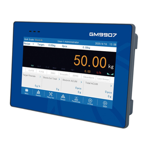
General Measure M04 User manual

M04
User’s Manual
M 0 4 - 0 0 1 6 0 7 0 1

Table
1. General Description..................................................................................................... - 1 -
1.1 Features and Functions.......................................................................................... - 1 -
1.2 Front Panel Description......................................................................................... - 1 -
1.3Rear Panel Description........................................................................................... - 2 -
1.4 Specification...........................................................................................................- 3 -
1.4.1Total Specification....................................................................................... - 3 -
1.4.2Analog Specification:............................................................................... - 3 -
1.4.3Digital Specification:................................................................................ - 3 -
2. Installation....................................................................................................................- 3 -
2.1Method.................................................................................................................... - 3 -
2.2Load Cell Connection............................................................................................. - 4 -
2.3 I/O Connection.......................................................................................................- 5 -
2.4Power Supply Connection...................................................................................... - 5 -
2.5Serial Port Connection............................................................................................ - 6 -
3. User Permission........................................................................................................... - 7 -
4. M Menu........................................................................................................................- 7 -
4.1System information...............................................................................................- 10 -
4.2Calibration.............................................................................................................- 12 -
4.3 Working Parameter.............................................................................................. - 13 -
4.4 Recipe Parameter................................................................................................. - 16 -
4.5 Communication Setting................................................................................. - 20 -
4.6 I/O Module...........................................................................................................- 20 -
4.6.1 Output define and Input define.................................................................- 21 -
4.6.2 IO test........................................................................................................- 23 -
4.7 Total......................................................................................................................- 24 -
5. Function......................................................................................................................- 24 -
5.1 Batch.................................................................................................................... - 24 -
5.2 Filling Level Controlling..................................................................................... - 24 -
5.2.1Three levels................................................................................................- 25 -
5.2.2Dual levels................................................................................................. - 25 -
5.2.3Signal level.................................................................................................- 25 -
6. Automatic Bagging.................................................................................................... - 25 -
6.1 WithHopper Mode Packaging..............................................................................- 25 -
6.2 Without Hopper Mode Packaging....................................................................... - 27 -
6.3 Dual Hoppers Interlock Mode Packaging........................................................... - 28 -
7. Dimension...................................................................................................................... - 29 -
8. A tta c hm e nt (M O DB US ad dre ss ) ....................................................................... - 30 -

M04 User Manual
M04-02110701 - 1 -
1. General Description
M04 Bagging controller is specially designed for single hopper packaging
controller. It is easier to operate, working faster and more precise with new algorithm.
USB port and two serial communication ports of the indicator made it easier to connect
with system. So it is widely used in various bagging machines for rice, feed, seed and
chemical etc.
1.1 Features and Functions
Working mode: with or without a material hopper
20 On/Off data input and output(8 in and 12 out), which can be defined by user.
Function of I/O testing to make bagging machine adjusting easier.
Automatic three-way feeding speed control and optional ‘fine filling inching’
function.
20 recipes can be stored for different weighing capacity.
Input & output data easily with USB port.
Material filling control function to make indicator and equipment connection easier.
Free fall correction.
Multilevel of digital filter
Batching times setting
Bag-patting function for powdery material bagging.
Automatic Zero-Tracking function.
Date and time setting
Identity setting for secondary user.
Two serial communication ports to connect with printer, computer or a second
display.
1.2 Front Panel Description

M04 User Manual
- 2 - M04-02110701
Display Area: show weighing data, status and some recipe information
Digital Button: input data and select parameter
Function Button: 【ZERO1】Clear weighing data.
【ZERO2】Check and set parameter accordingly by shortcut button.(Need
admittance.)
【M】Set parameters
【ESC】Exit and return to main menu.
【ENTER】Confirm status.
1.3Rear Panel Description

M04 User Manual
M04-02110701 - 3 -
1.4 Specification
1.4.1Total Specification
Power Supply: AC100V-240V 50Hz/60Hz±2%
Power Supply Filter: Installed inside.
Working Temperatures : -10~40℃
Maximum Humidity: 90% R.H without dew
Power: 15W
Dimension: 225×100×120mm
1.4.2Analog Specification:
Power Source for load cells : DC5V 125mA(MAX)
Input Resistance: 10MΩ
Zero Point Adjustment range:
0.02~4mV (When the transducer is 1mV/V.)
0.02~8mV (When the transducer is 2mV/V.)
0.02~12mV (When the transducer is 3mV/V.)
Minimum Input sensitivity: 0.02uV/d
Input Range : 0.2~15mV
A/D Type: Sigma - Delta
A/D Rate: 120Times/Second,240Times/Second,480Times/Second,960Times/Second
Non-Linear:0.01% F.S
Gain Drifting:10PPM/℃
Maximum Accuracy of Display:1/100,000
1.4.3Digital Specification:
Display:5 inch TFT LCD Display (800*480)
Negative Display:“—”
Overload Display:“OFL”
Decimal Position:5 options
2. Installation
2.1Method
M04 packing controller uses AC100V-240V 50Hz/60Hz±2% power supply with
grounding to guarantee the safety of the controller and other equipment connected.
The cables connecting M04 to load cells should not bind with other cables,especially
power supply cables, and must use shielded cables, because the signals from the load cells

M04 User Manual
- 4 - M04-02110701
is low voltage analog signals.
Note:Please DON’T connect the Ground Wire of the controller directly to the GND of
other equipment.
To install the M04 into a control box, please refer to the last chapter of this manual first,
and make appropriate installation holes according to the position of screw holes on the
housing box, remove the fixing plates on both sides of M04, put the controller into the
housing box, fix it with the fixing plates and lock them with screws.
2.2Load Cell Connection
Please refer to the picture below to connect load cells to the M04 controller.
When you chose the six-wired load cells, you must bridge the SN+ with EX+ and
bridge the SN- with EX-.
Please keep the cables of load cells clear of other cables.
EX+: Excitation+ EX-: Excitation- SN+: Sense+ SN-: Sense- SIG+: Signal+ SIG-: Signal-

M04 User Manual
M04-02110701 - 5 -
2.3 I/O Connection
M04 Controller uses optoelectronic isolation technology to transfer the ON/OFF data.
This needs 24V DC power supply that is provided from outside, through the 24V+ and the
24V-. The I/O signal input is low level effective. The output is open-collector output. The
driving current can reach 500mA.
Figure: Input Schematics(Take IN1,IN3,IN5,IN7 for example)
Figure: Output Schematics(Take OU1, OUT9 for example)
User can define I/O signals. (See 4.6 for details.)
2.4Power Supply Connection
M04 packing controller uses AC100V-240V 50Hz/60Hz±2% power supply with

M04 User Manual
- 6 - M04-02110701
grounding. The Correct connections are depicted below.
Power Supply Connector: L-Live Wire G-Ground Wire N-Null Wire
2.5Serial Port Connection
M04 can provide two serial ports. It is depicted below. One for RS485, the other is for
optional RS232 or RS485. Serial ports support MODBUS mode, rEAd mode, Cont mode
and printing.
Connection between M04 and a Host Computer(RS-232)

M04 User Manual
M04-02110701 - 7 -
Connection between M04 and a Host Computer(RS-485)
3. User Permission
M04 provides different powers for operator, administrator and system administrator in
order to avoid wrong operation. Among them, system administrator holds all operation
rights. The permission of operator and administrator hold limited permission as below:
Permissi
on
Operation
Operator
Not allow to set calibration parameter or calibration.
Not allow to revise the working parameter.
Not allow to define I/O.
Not allow to delete or clear accumulated value.
Allow to enter System information check version.
Technici
an
Not allow to revise weigher structure parameter in Working parameter.
Not allow to or set shortcut define.
Operators log on when connect power.
User log in identity shifted by pressing Zero button. The initial password is
000000.
To set password of administrator in User administration of System Info.
4. M Menu
Checking and revising parameters through M menu list.

M04 User Manual
- 8 - M04-02110701
As figure showed above, the left side is parameter list; the right side is brief
description and parameter information.
【▲】&【▼】:Shift parameter option.
【ENTER】: Check and set parameter information.
【ESC】: Return to main menu.
List
Parameters
Parameter list
Description
M
Recipe
parameter
Result waiting
Result waiting setting
Result waiting
timer
Result waiting timer setting
Overlimit /
underlimit
Over/under weight and way
parameters setting
Free fall
correction
Free fall correction and other
parameters setting
Fine flow inching
Fine flow inching mode setting
Under-compensati
on
Compensation filling parameter
setting
Pat parameters
Pat time and method setting
Other parameters
Single hopper combination Nos
setting
Working
parameter
Basic parameter
Basic parameter setting
Advanced
parameter
Operation parameter setting

M04 User Manual
M04-02110701 - 9 -
Coding parameter
Coding parameter setting
Weigher structure
Weigher parameter setting(Only for
administrator)
Calibration
Weighing
parameter
Unit,decimal point,scale range
setting
Zero calibration
Zero point calibration
Weight
calibration
weighing value calibration
Total
Recipes list
Read, clear, print recipe information
I/O Module
Output define
Define output port
Input define
Define input port
IO test
Test port connection
Serial port
parameter
RS485
Serial port1(RS485) parameter
setting
Optional
RS232/RS485
Serial port2(RS232/RS485)
parameter setting.Communication
mode refers to 2.5
Serial port option
Serial port3(optional) setting, but still
not open.
Printing
parameter
Printing parameter setting
System info.
User
administration
User password administration
Password
administration
Password administration of all
parameters(Calibration password
switch is ON)
Recover/back up
All parameters recover with original
setting and data back up.
USB data input
Input working parameter, recipes
parameter,calibration parameter and
others parameter.
USB data output
Output working parameter, recipes
parameter,calibration parameter and
others parameter from indicator.
Shortcut setting
Function of figure button setting

M04 User Manual
- 10 - M04-02110701
System version
Check software version and set
system time.
4.1System information
Technician and administrator can edit user administration, exercise password
administration, recover/back up data, set shortcut and check version through System info..
【 】&【 】:Exchange functional option.
【▲】&【▼】:Exchange selected function item.
【ENTER】: Edit parameters.
【ESC】: Exit.
System
information
Information item
Description
User
administration
1.User login
User ID. (Not allow to edit)
2.Permission
setting
Option:technician and operator
3.Password
ON/OFF
Option: ON/OFF.No need enter password
when OFF.
4.Edit password
Set/edit login password.Need to input
original password when edit.
Password
administration
1.Recipe parameter
password
Optional ON/OFF, user no need to input
password when edit parameters.【ZERO2】can
edit parameter password. The initial password is
000000.
2.Working
parameter password
3.Calibration
password
4.I/O module
password
5.System
information
password
Recover/back
up
1. All parameters
initializing
Press
【ENTER】
will initialize all parameters.
2. Calibration
parameter
Press【ENTER】will initialize calibration
parameter.

M04 User Manual
M04-02110701 - 11 -
initializing
3.Basic parameter
initializing
Press【ENTER】will initialize fundamental
parameter.
4.Recipe parameter
initializing
Press【ENTER】will initialize recipe
parameter.
5.I/O module define
initializing
Press【ENTER】will initialize I/O module
define.
6. Advanced
parameter
initializing
Press【ENTER】will initialize high rank
parameter.
7. Shortcut define
initializing
Press【ENTER】will initialize shortcut define.
8.Execute parameter
back up
Press【ENTER】will back up current
parameters.
9.Data recover/back
up
Press【ENTER】will recover parameter as
back up data.
USB data input
1. All parameters
Input all parameters through USB
2.Working
parameter
Input working parameter through USB
3.Recipe parameter
Input recipe parameter through USB
4.Calibration
parameter
Input calibration parameter through USB.
5.I/O parameter
Input I/O parameter through USB.
6.Serial port
parameter
Input serial port parameter through USB.
USB data
output
1. All parameters
Output all parameters through USB.
2.Working
parameter
Output working parameter through USB
3.Recipe parameter
Output recipe parameter through USB
4.Calibration
parameter
Output calibration parameter through USB.
5.I/O parameter
Output I/O parameter through USB.
6.Serial port
parameter
Output serial port parameter through USB.
Shortcut
1.Digit-1
Initial value:recipe
Press【ENTER】to

M04 User Manual
- 12 - M04-02110701
setting
parameter
define shortcut.
【 】&【 】:Turn
pages.
2.Digit-2
Initial value:working
parameter
3.Digit-3
Initial
value:calibration
4.Digit-←
Initial value:batch
5. Digit-4
Initial value:total
6.Digit-5
Initial value:I/O
module
7.Digit-6
Initial value:serial port
parameter
【▲】&【▼】:Select
functional parameter
value
8.Digit-0
Initial value:user login
9.Digit-7
Initial value:system
info.
10.Digit-8
Initial value:recipe ID
11.Digit-9
Initial value:target
value
12.Digit-.,?
Initial value:no value.
Note: For defined digit button, you can enter indicator by press them accordingly. For
example, digit 1 defined Recipe parameter; you enter recipe parameter if you press 1. If
digit1 defined Run, the indicator works when press 1.
4.2Calibration
Calibration should be done when a M04 indicator is used at the first time, or the preset
parameters can’t meet the user’s demand due to change any part of the weighing/bagging
system.
To enter calibration parameter need to input correct password as it is protected by
password per International Standard. Calibration password can be set in Password
Administration of System Info.
As the Calibration interface showed,
【 】&【 】:Exchange calibration parameter.
【▲】&【▼】:Select parameter items.
【ENTER】:Enter and edit parameter.
【ESC】:Exit.
Calibrati
Calibration
Description

M04 User Manual
M04-02110701 - 13 -
on
paramete
r
items
Weighing
parameter
1.Unit
Initial value:kg. Four types: g/kg/t/lb
2.Decimal point
Initial value:0.000. Five types:0~0.0000
3.Load cell
sensitivity
Initial value:2mV/V. Three types:1~3mV/V.
4.Mini scale
division
Initial value:1. Six types:1/2/5/10/20/50.
5.Max scale range
Initial value: 10.000. ≤ Min. Scale Division×100000
Zero
calibration
Present weight
Display present weight
value.
Press 【ENTER】to set
zero point with clearing
weighing hopper.
Present voltage
Display the present
output voltage of load
cell
Weight
calibration
Present weight
Display present
weighing value
Adding weight and
inputting weighing value
to finish calibration.
Relative voltage
value
Display output voltage
value with weight
4.3 Working Parameter
The working parameter interface showed:
【 】&【 】:Switch working parameter.
【▲】&【▼】:Switch items of working parameter.
Press 【ENTER】button, can enter and edit parameters.
Press 【ESC】button, exit.
Worki ng
parame te
r items
Pa ram eter s
De scrip tion
Basic
parameter
1.Power-up
zero
Optional ON/OFF.If ON, the controller will be auto zero
when power up
Initial value: OFF.
2.Zero range
Initial value: 50. Range: 1~99.(Percentage)
3.Stable range
The indicator is stable within this range.

M04 User Manual
- 14 - M04-02110701
Initial value: 2. Range:0~99(d).
4.Stable timer
Initial value: 0.3. Range: 0.1~9.9.
5.Zero track
range
The controller will be auto zero within the range. Zero
tracking will not proceed if Zero.
Initial value: 0. Range :0~9(d).
6.Zero track
timer
Initial value:2.0. Range: 0.1~99.9
7.Digital filter
AD digital filter parameter:0 for non filter, 9 for best
filtering. Initial value: 7. Range: 0~9.
8.Advanced
NO/OFF
Optional ON/OFF.The second filter will proceed on the
basis of digital filter. Initial value:ON.
9.A/D
sampling rate
Option:120 times per second,240 times per second, 480
times per second,960 times per second.
Advanced
parameter
1.Auto zero
interval
Zeroing after number times bagging. No zeroing for first
time. Initial value: 0.
Range:0~99. Only for bagging with hopper.
2. Filling
process
filter
Filling process filter parameter:
9: Strongest filter.
4: Initial value.
1~9: Range.
3. Waiting
process
filter
Result waiting filter parameter:
9: Strongest filter.
5:Initial value.
1~9:Range.
4.Discharge
process filter
Discharging filter process filter
9: Strongest filter.
3: Initial value.
1~9:Range
5.Running
stable timeout
Initial value:0.0. Range: 0~99.9 (per second).
6.Waiting
mode
Judgment of Waiting: closing inching feeding and stable.
Delay of Waiting:closing inching feeding and stable after
holding time.
Initial value: By delay timer
7.Discharge
Discharge directly:the controller will discharge directly

M04 User Manual
M04-02110701 - 15 -
mode
after value setting.
Discharge allowed:the controller is waiting for the signal
of allowing to discharge after value setting.
8.Without
hopper filling
mode
Option: Gross weight and Net weight.
First clear tare, then begin packing with net weight value.
Initial value: net weight packing.
9.Manual
discharge add
to total
Option:ON/OFF. The value will included in total when
ON.
10.Final
weight holding
Option: ON/OFF.Fixed value holding until discharging
weight value lower than zero value,showing present
weight.
Coding
parameter
1. Coding
device
ON/OFF
Option: ON/OFF.ON: Printing. Initial value: OFF.
2.Coding start
delay timer
Printing after clipping bag.
Initial value:0.5. Range: 0.0~99.9 second.
3.Coding
duration timer
Printing efficient time. Initial value: 0.5. Range: 0.0~99.9
second.
4.Allow
fill/discharge
when coding
Option:ON/OFF.Non-stop when feeding or discharging.
Initial value: OFF.
Weigher
Structure
1.Weigher
structure
With weighing hopper and without weighing hopper
2.Working
mode
Option:Single hopper/Scale A interlock/Scale B interlock;
Initial value: Single hopper.
3.Filling mode
Option: Solo filling and combination filling. Initial
value:combination filling
Combination filling:
Coarse flow/ medium flow/ fine flow
Medium flow/ fine flow
Fine flow
Solo filling:
Coarse flow
Medium flow
Fine flow

M04 User Manual
- 16 - M04-02110701
4.Dual hopper
unlock bag
mode
Select discharge mode. Initial value: discharge at different
time.
5.Conveyor
start delay
timer
Conveyor start time.Initial value:0. Range: 0~99.9seconds.
6.Conveyor
running timer
Conveyor running timer setting. Initial value: 0.
Range:0~99.9 seconds.
7.Next filling
delay timer
Repeat feeding delay time. Initial value:0. Range: 0~99.9
seconds.
4.4 Recipe Parameter
When move to recipe parameter,
Enter by Button 1 to select and edit 1-20 recipes accordingly.
Enter selected recipe parameter.
In recipe parameter interface:
【 】&【 】Changing recipe parameter.
【▲】&【▼】Changing items of recipe parameter.
【ENTER】: Entering and editing item recipe parameter.
【ESC】Exit.
Recipe
parameter
Parameters
Description

M04 User Manual
M04-02110701 - 17 -
item
Value
Weighing value parameter setting.
1.Target
Target value setting.
2.Coarse flow
When present weight ≥ Target value-Coarse flow value, and
then shutoff coarse flow filling.
3.Medium
flow
When present weight ≥ Target value-Medium flow value,
and then shutoff medium filling.
4.Free fall
When present weight ≥ Target value-Free fall value,and then
shutoff fine flow.
5.Near zero
band
When present weight≤ Near zero band, start t5 discharging
delay timer.
Timer
Feeding delay timer parameter setting
1.Filling
delay
With hopper mode:Begin feeding after filling delay. Zeroing
in stability criterion at first if need.
Without hopper mode:After bag locked,
the indicator off tare and display net weight
in stability criterion after filling delay.
2.COMP.
inhibit timer
(Co-F)
Fast filling is ON to avoid impulsive force within COMP.
inhibit timer (Co-F).
3.COMP.
inhibit timer
(Me-F)
Medium filling is ON after fast filling completed to avoid
impulsive force within COMP. inhibit timer (Me-F).
4.COMP.
inhibit
timer(Fi-F)
Fine filling is ON after medium feeding completed to avoid
impulsive force within COMP. inhibit timer (Fi-F).
5.Over/under
alarm timer
ON: Alarm timer will output when over/ under value.
6.Result
waiting timer
By delay timer: Closing fine filling and starting waiting, will
move on to next step.
7.Discharge
delay timer
Discharging delay timer will start when weighing value≤zero
range value,if finished, then closed discharging.
8.Bag locked
delay timer
By bag locked delay timer, bag locked completed.
9.Unlock bag
pre-delay
timer
With hopper mode: When finish discharging, bag unlocked
after unlock bag pre-delay timer.
Without hopper mode: When finish patting bag, bag
unlocked after unlock bag pre-delay timer.

M04 User Manual
- 18 - M04-02110701
Over/un
der
Over/under tolerance-alarm parameter setting
1.Over/under
ON/OFF
Option: ON/OFF. Over/under judgment when ON.
2.Over/under
pause
Option:ON/OFF.The indicator will stop when over or under.
Press 【ENTER】will restart.
3.Over value
When present weight ≥ target
value + over value, it is over tolerance.
4.Under value
When present weight ≤ target
value - under value, it is under tolerance.
Initial value:0.
Auto
free fall
correctio
n
Free fall compensation parameter setting
1.Reference
samples PCS
The indicator will make the average of thus times as
compensation value.
Initial value:0.
Range:0~99.
Note:If set 0, free fall compensation will close.
2.Correction
effective
range
If free fall value is more than the
percent of target value, the value will not
be accounted to average.
Initial value:2.
Range:0.0~9.9(Percent of target value)
3.Correction
percentage
Option: Four types between 25% to 100%.
Initial value: 50%.
Fine
flow
mode
Fine flow jogging parameter setting
1.Jog flow
ON/OFF
Option:ON/OFF. Jog flow is proceeding when ON.
Initial value: OFF.
2.Flow-On
timer
Flow-On timer within a cycle when fine flow output.
Initial value: 0.5.
Range:0.0~99.9 seconds.
3.Flow-Off
timer
Flow-Off timer within a cycle when fine flow output.
Initial value: 0.5.
Range:0.0~99.9 second.
Under
limit
compens
ation
Under limit compensation parameter setting.
1.Compensati
on times
Initial value: 0.
Range:0~9.
Note: The compensation will be off when sets 0.
2.Flow-On
timer
Flow-On timer within a cycle when compensation filling
output.
Initial value: 0.5
Range:0.0~99.9 seconds.
Table of contents
Other General Measure Controllers manuals