TAC Forta M400 User manual

1 (6) 0-003-2060-1 (EN)We reserve the right to make minor changes.
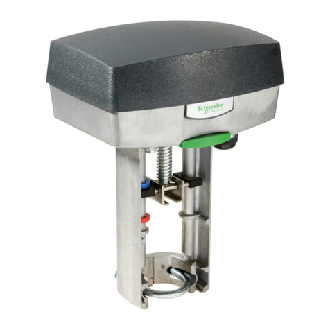
M400 is an electro-mechanical actuator for the control of
two-way and three-way plug valves in:
• heating systems
• air handling systems
M400 is primarily designed for applications where the
demands on actuator speed and thrust are small.
The actuator can not be equipped with Self Testing
Device STS.
M400 is either controlled by an increase/decrease signal
or by a modulating 2–10 V control signal.
The electronic circuitry of the actuator ensures that the
running time is the same, regardless of the stroke of the
valve in question.
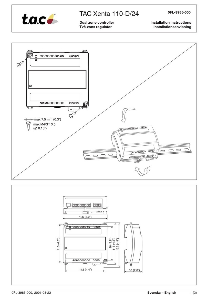
It is easy to mount and connect the actuator. It can be
mounted directly onto TAC’s control valves, without any
mounting kit.
The working range of the actuator is adjusted
automatically depending on the stroke of the valve. The
electronic circuitry of the actuator then takes care of the
adjustment of the valve end positions.
The actuator is supplied by 24 V AC. It can provide
16 V DC voltage supply for older TAC controllers.
Actuator for Valves
G-40-22
11 Jun 2003
TECHNICAL DATA, M400
Part numbers ....................... see the table on the next page
Supply voltage ............................ 24 V AC ±10%, 50–60 Hz
Power consumption ........................................ average 6 VA
Transformer sizing...................................................... 30 VA
Running time:
Modulating.................................................................. 60 s
Increase/decrease............................................ 300 s/60 s
Stroke ........................................ 10–32 mm (0.39 - 1.26 in.)
Factory set stroke................................... 20 mm (0.79 in.)
Thrust .............................................................400 N (90 lbf)
Duty cycle .......................................... max. 20%/60 minutes
Analog input:
Voltage .................................................................. 0–10 V
Impedance ..................................................... min 100 kΩ
Digital inputs VH–VC:
Voltage across open input .................................. 24 V AC
Current through closed input.................................... 5 mA
Pulse time ....................................................... min. 20 ms
Output G1:
Voltage .....................................................16 V DC ±0,3 V
Load ......................................... 25 mA, short-circuit proof
Output Y:
Voltage ................................................... 2-10 V (0-100%)
Load ......................................................................... 2 mA
Ambient temperature:
Operation ............................ –10 – +50 °C (14°F - 122°F)
Storage................................ –10 – +50 °C (14°F - 122°F)
Ambient humidity ............................................max. 90% RH
Enclosure rating........................................................... IP 54
Standards:
Emission............................................... EN 50081-1:1992
Immunity............................................... EN 50082-1:1992
Heat................................................................. IEC-68-2-2
Humidity .......................................................... IEC-68-2-3
Cold ................................................................. IEC-68-2-1
Salt mist ........................................................ IEC-68-2-11
Vibration .......................................................... IEC-68-2-6
Material:
Housing ............................................................ aluminium
Cover........................................................ ABS/PC plastic
Color ...........................................................aluminium/black
Weight ..........................................................1.8 kg (3.96 lb)
Dimensions.................... refer to the table on the next page
TAC Forta
M400

0-003-2060-1(EN) 2 (6)
Designation Explanation Part number
M400 modulating control signal or increase/decrease signal 880-0230-020
M400-S2 modulating control signal or increase/decrease signal and end point
switches 880-0231-020
The actuator
The step motor of the actuator turns a
screw via a gear wheel. The motor
receives a control signal from a
controller. The screw gets a linear
movement which moves the stem of the
valve.
Control signal
M400 can either be controlled by an
increase/decrease signal or by a
variable direct voltage.
If an increase/decrease signal is used,
the actuator normally moves inwards on
an increase signal and outwards on a
decrease signal, see Settings.
Manual operation
There is a manual operation handle on
the actuator, see figure 2. When it is
lowered, the motor stops. Then, the
actuator can be operated manually if
the handle is turned.
Position feedback
Forta actuators are equipped with a 2–
10 V DC position feedback signal,
where 2 V always corresponds to the
closed position and 10 V to the open
position.
End point switches
When actuators are controlled in
sequence, it is possible to use the end
point switches that have set positions.
They will toggle when the valve is fully
open or fully closed, respectively.
Manual
operation
handle
PART NUMBERS
FUNCTION
Figure 1
DIMENSIONS
173
44
315
82
242
117
(6.81)
(4.60)
(9.53)
(3.235)
(1.73)
(12.40)
Mått: mm
Dimensions: (in.)
Figure 2

3 (6) 0-003-2060-1 (EN)
The actuator may be mounted
horizontally, vertically and in any
position in between, but not upside
down, see figure 3.
N.B.! Do not use the actuator for the
DN15 valves V298, V282, V294, V384,
V386 and V394.
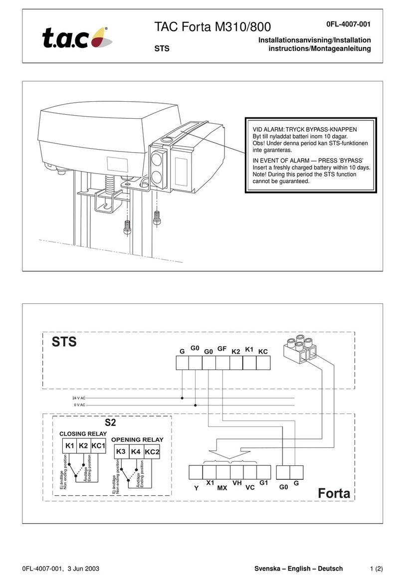
To mount the actuator on a valve, slide
the actuator onto the valve neck, thus
making the square nut on the valve
spindle fit into the groove on the cross
bar. Then slide the brace into the
groove on the valve neck and secure
the nuts.
MOUNTING
CONNECTIONS
N.B.! When installed with 3
conductors, where the control signal
reference is connected to G0, the motor
current of the actuator will cause
varying voltage loss in the cable and
thus in the reference level. Forta, which
has a highly sensitive control signal
input, will detect the varying signal and
follow it, which makes it difficult for the
actuator to find a stable position.
This variation may be accepted in
simplified installations on the following
conditions: the cables between the
controller and actuator
are shorter than 100 m (328 ft.), the
cross-sectional area is larger than
1,5 mm2 (AWG 16) and the cables are
only connected to one actuator. Please
refer to the figures labelled “Simplified
installation” for wiring instructions.
Cable lengths
The cables to G, G0 and G1 should be
max. 100 m (328 ft.) and have a cross-
sectional area of min. 1,5 mm² (AWG
16).
Other cables should be max. 200 m
(656 ft.) and have a cross-sectional
area of min. 0,5 mm² (AWG 20).
Block Function Description
G 24 V AC Supply
G0 24 V AC rtrn voltage
X1 Input Control sign-
MX Input, neutral als (VH, VC
VH Increase short-circuited
VC Decrease to G0)
G1 16 V DC Supply for RC
Y 0–100 % Feedback
signal
}
}
2V
10V
NORM
VH VC y
10V
2V
VH VC y
10V
X1
10V
y
INV
NORM
X1
10V
0(2)V 10V
y
INV
2V 0(2)V 2V
YX1MXVHVCG1
1
2
3
4
5
6
7
8
G0 G
Terminal
block
YX1 MX VH VC G1 G0 G
Forta P
24 V
0 V
K1 K2 KC1
CLOSING RELAY
OPENING RELAY
S2
Ej endläge
Non ending position
Endläge
Ending position
KC2
K3 K4
Ej endläge
Non ending position
Endläge
Ending position
Figure 3
Figure 4

0-003-2060-1(EN) 4 (6)
WIRING EXAMPLES
Figure 5
Forta
Controller
Increase/decrease control
Modulating control, 24 V AC supply to the controller
(TAC 239W, TAC 6711, TAC Xenta, TAC 8000, TAC 230U, TAC 2000, TAC 9000, TAC 77xx)
Modulating control, 16 V DC supply to the controller
(TAC 218E/RM, TAC 221L, TAC 228R/RL/RF, TAC 239W, TAC 258R/RL, TAC 268R/RL/RF)
Modulating control, galvanically isolated output in the controller (TAC 6501, TAC 6505)
Forta
Controller Forta
Controller
Normal installation (4 wires to the actuator) Short cable installation (3 wires to the actuator)
FortaController FortaController
Normal installation (5 wires to the actuator) Short cable installation (4 wires to the actuator)
FortaController
Forta
Controller
Normal installation (5 wires to the actuator) PU unit installation (4 wires to the actuator)
Control
cabinet
0 V
24 V AC
G0
GK1
K2
KC G0
G
VH
VC
G0
G
X1
MX
Y
M
0 V
24 V AC
G
G0
0 V
24 V AC
G0
G
Y
MG0
G
X1
MX
0 V
2
4 V AC
G0
16 V
G1
Y
MG0
G
G1
X1
MX
0 V
2
4 V AC
G0
16 V
G1
Y
MG0
G
G1
X1
MX
0 V
2
4 V AC
G0
G+
OUT
–G0
G
G1
X1
MX
16 V
0 V
24 V AC
G0
G+
OUT
–G0
G
X1
MX
16 V
G1 G0
G
PU

5 (6) 0-003-2060-1 (EN)
SETTINGS
Function in the Description
“OFF” position “ON” position
Modulating Increase/decrease Control
– Sequence Control
2-10 V 0-10 V Voltage range
6-10 V, 5-10 V 2-6 V, 0-5 V Part of voltage range
60 s, 0% 300 s, 50% Running time (Security function)
Normal Inverted Direction of movement
Normal Linear/Logarithmic Valve characteristic
Operation End position adjustment Operation/End position adjustment
INC
6-10, 5-10
ADJ
LIN/LG
INV
300 s / 50%
0-10
2-6, 0-5
SEQ
OP
NORM
NORM
0
% / 60 s
2-10
– – –
MOD
12345678
O
N
There are eight switches in a row on the
circuit board, see figure 6.
Note! Switch 0% / 60 s, 300 s / 50%
has a double function, see below!
M400: On delivery, all switches are in
the “OFF” position except for the third
one.
Control signal—MOD/INC
M400 can either be controlled by an
increase/decrease signal or by a
variable direct voltage, a so called
modulating signal, so a certain voltage
level corresponds to a certain position.
Sequence or parallel control—
– – –/SEQ
With sequence or parallel control, two
actuators can be controlled by only one
control signal.
You can choose which part of a voltage
range to use, the upper one 6-10 V
(5-10 V) or the lower one 2-6 V (0-5 V).
If the switch »NORM/INV« is in the
NORM position, the higher voltage
corresponds to 0% flow and the lower
one to 100%. To achieve the opposite
function, the switch »NORM/INV«
should be put in the INV position.
Note! If sequence or parallel control is
not used, the switch »– – –/SEQ« must
be in the left position, as the switch for
modulating or increase/decrease
control »MOD/INC« is not valid during
sequence or parallel control.
Voltage range—2-10/0-10
You can choose whether to use the
control signal voltage range 2-10 V or
0-10 V.
Part of voltage range—
6-10, 5-10/2-6, 0-5
You can choose which part of a voltage
range to use, the upper one 6-10 V
(5-10 V) or the lower one 2-6 V
(0-5 V). If the switch is in the NORM
position, the higher voltage corresponds
to 0% and the lower one to 100%. To
achieve the opposite function, the
switch should be put in its INV position.
Running time—60 s/300 s
During increase/decrease control, you
can choose between 60 s or 300 s
running time. During modulating control,
the running time is always 15 s/20 s.
Security function—0% / 50%
At 2–10 V control signal you can select
which security function you want the
actuator to have.
If the actuator is used for heating
control and switch 5 is ON (50%), the
actuator will open the valve halfway if
the control signal disappears, e.g. if the
X1 connection is unplugged.
If, instead, you want the valve closed,
set switch 5 to OFF (0%).
Note! The direction of movement is also
significant. See Installation Instruction
0FL-4006.
Direction of movement—NORM/INV
When normal direction of movement is
used, the screw of the actuator moves
inwards when the control voltage
decreases or if the actuator gets an
increase signal. With the switch
»NORM/INV«, the direction of
movement can be changed.
Linearization—NORM/LIN/LG
It is possible to choose whether the
motorized valve characteristics should
be affected or remain unchanged. If
you wish for the characteristics to be
affected, the choice »LIN/LG« will make
the characteristics of an equally
modified percentage (EQM) valve
almost linear. A motorized valve
equipped with a linear valve will operate
with “Quick open characteristics”, i.e.
when the control signal is only
increased a little, the valve will be
almost completely open.
Note! For the actuator to register new
settings of the switches, the supply
voltage must be cut or the manual
operation handle lowered when the
settings are done, and then it must be
raised again. (This does not apply to
the switch »OP/ADJ«.)
End position adjustment—OP/ADJ
The switch is used to adjust the end
positions when the actuator is in
operation.
Figure 6

0-003-2060-1(EN) 6 (6)
ACTUATOR INSTALLATION
The switches on the circuit board
should be set before the actuator is
installed. There are no other switches
or potentiometers that should be set or
adjusted.
To make an end position adjustment,
you only have to switch the switch
»OP/ADJ« into its ADJ position, when
the supply voltage has been turned on,
and then back to its OP position.
When an end position adjustment is
made, Forta closes the valve and opens
it fully. The adjustment is finished by
the actuator closing the valve again; the
electronic circuitry then adjusts the
stroke and the running time to the
valve. The set values are stored in the
EEPROM of the actuator so that they
will remain after a loss of voltage.
When the end position adjustment is
complete, the actuator starts to control
the valve according to the control
signal.
MAINTENANCE
The actuator is maintenance-free.
ACCESSORIES
Circuit board, M400............................................................................... 1-001-0671-0
TAC Forta Handbook (GB) ...................................................................... 0-004-7804
S2-Forta ............................................................................................... 880-0104-000
TAC AB, Jägershillgatan 18, SE-213 75 MALMÖ, SWEDEN, +46 40 38 68 50 (switchboard), www.tac.com
Table of contents
Other TAC Controllers manuals