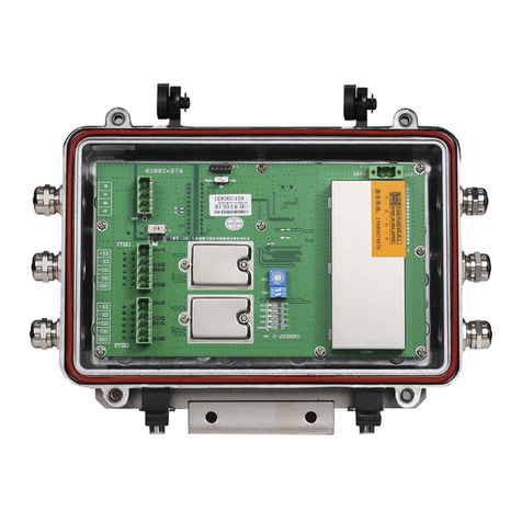
General Measure GM8802C-D User manual

GM8802C-D
User Manual
GM8802C-D110101
48010224231000

CONTENTS
1 General Description ..................................................................................................1
1.1 Functions and Features.......................................................................................1
1.2 Front Panel.........................................................................................................2
1.3 Technical Specifications.....................................................................................3
1.4 Dimensions........................................................................................................5
2 Installation ................................................................................................................6
2.1 Connection of Power Supply .............................................................................6
2.2 Connection of Load Cell....................................................................................6
2.3 Connection of Serial Interface........................................................................100
3 Calibration ..............................................................................................................11
3.1 Descriptions of Calibration..............................................................................61
3.2 Flow Chart of Setting Parameters ..................................................................122
3.3 Millivolt Value Display....................................................................................17
3.4 Calibration with Weight ...................................................................................18
3.5 Calibration without Weight ..............................................................................19
3.6 Serial Ports Calibration Switch......................................................................211
3.7 Log Table for Parameter Calibration 1...........................................................231
3.8 Log Table for Parameter Calibration 2...........................................................233

4 Setting Parameter ..............................................................................................244
4.1 Flow Chart of Setting Parameters...............................................................244
4.2 Method of Setting Parameters ....................................................................311
5 Serial Communication.......................................................................................333
5.1 EASY Protocol.............................................................................................33
5.2 RE Protocol..................................................................................................36
5.3 RS Protocol ..................................................................................................39
5.4 SP1 Protocol.................................................................................................58
5.5 Modbus Protocol..........................................................................................77
5.6 tt TOLEDO Protocol ....................................................................................98
5.7 RDP Philips Protocol....................................................................................99
6 Operation...........................................................................................................101
6.1 Zeroing Operation.....................................................................................101
6.2 Inputting Password....................................................................................101
6.3 Setting Password.......................................................................................103
6.4 Recover Initial Settings.............................................................................103
7 Display Test.......................................................................................................107
8 Errors and Alarm Messages...............................................................................108

GM8802C-D Weighing Transmitter
GM8802C-D110101 1
1 General Description
GM8802C-D weighing transmitter is specially designed for industrial weighing field. It
has the features of steady characteristics, easy to operate. It is widely used in concrete,
bitumen mixing plants, blast furnace and converter, etc..
1.1 Functions and Features
Small dimension, handsome appearance, easy to operate.
Applicable to all kinds of resistance strain gauge bridge load cell.
Front panel numerical calibration
Multilevel of digital filter
Automatic zero –tracking
Automatic zeroing when power up
Bothway serial port(RS-232/RS-485)
Calibration via serial interface

GM8802C-DWeighing Transmitter
2GM8802C-D110101
1.2 Front Panel
Main Display: 6 digits, for displaying weight, analog output value, and the information of
parameters.
Status Indicator Lamp:
ZERO: Zero position. Light up when present weight on the platform is within
0±1/4d.
STAB:Light up when changes of weight values are within stability criterion range.

GM8802C-D Weighing Transmitter
GM8802C-D110101 3
DATA: Light up when data transmission.
Keypad:
key to zeroing and exit from the current function status.
key to choose the parameter items.
key to choose the functions of parameter setting.
key to enter items (when setting parameters or calibration) or confirm the current
function.
1.3 Technical Specifications
1.3.1 General Specifications:
Power supply :DC24V ± 5%
Working temperatures :-10~40℃
Humidity :90% R.H without dew
Power :about 4W
Dimension :82×92×45(mm)

GM8802C-DWeighing Transmitter
4GM8802C-D110101
1.3.2 Analog Part:
Load cell exciting voltage :DC5V 200mA(MAX)
Input resistance :10MΩ
Zero point adjustment range:0.2~8mV when the sensor is 2mV/V;
0.02~12mV when the sensor is 3mV/V;
Input sensitivity :0.1uV/d
Input range:0.2~10.5mV (when the sensor is 2mV/V)
0.02~15mV(when the sensor is 3mV/V)
A/D conversion:Sigma - Delta
A/D conversion speed:120times/second
Non-linear :0.01% F.S
Gain drifting :10PPM/℃
Precision:1/30000
1.3.3 Digital Part:
Display :6 high light red LEDs
Negative data display :“-”
Overflow display:“OFL”
Position of decimal point :5 options
Keypad:4 beep keys

GM8802C-D Weighing Transmitter
GM8802C-D110101 5
1.4 Dimensions
Dimension of front panel:
Length
:
82mm
Width
:
92mm
Hight:45mm

GM8802C-DWeighing Transmitter
6GM8802C-D110101
2 Installation
2.1 Connection of Power Supply
GM880C-D weighing transmitter uses 24V direct-current power and the connection is
as follows:
2.2 Connection of Load Cell
GM8802C-D weighing transmitter need to be connected with bridge type resistance
strain gauge load cells as below figures. When you chose the four-wired load cells, you
must bridge the SN+ with EX+ and bridge the SN-with EX-.
DC+:Positive pole
DC-:Negative pole

GM8802C-D Weighing Transmitter
GM8802C-D110101 7
The signal definition of each port of the load cell connector as follows:
Port EX+ SN+ EX- SN- SIG+ SIG- AGI
Connection Excitation+ Sense+ Excitation- Sense- Signal+ Signal-Shield
2.2.1 6-Wired Connection
Load cell

GM8802C-DWeighing Transmitter
8GM8802C-D110101
2.2.2 4-Wired Connection
Load cell

GM8802C-D Weighing Transmitter
GM8802C-D110101 9
1. The signals from the load cells are low voltage analog signals, which are easily
affected by electro-noise, so the cables connecting load cells to indicator should use
shielded cables, and not bind with other cables, especially power supply cables.
2. For the application of short-transporting-distance and lower precision, 4-wired
connection can be used; otherwise, 6-wired should be used.
3. For the application of multi-load cell in parallel connection, the sensitivity of each
load cell (mV/V) must be same.

GM8802C-DWeighing Transmitter
10 GM8802C-D110101
2.3 Connection of Serial Interface
GM8802C-D supplies one serial interface that
can be chosen as RS232 or RS485. The definition is as follows:
RS232 Connection::RS485 Connection:
C
o
n
t
r
o
l
l
e
r
1
A
B
GND
C
o
n
t
r
o
l
l
e
r
n
A
B
GND
C
o
m
p
u
t
e
r
A
B
GND
GND is ground of RS485, it can very
much improve communication
quality via connecting with GND by
low-resistance wire when there is a lot
of disturbance in working field.
.
.
.

GM8802C-D Weighing Transmitter
GM8802C-D110101 11
3 Calibration
3.1 Descriptions of Calibration
(1)Calibration procedure must be executed when a GM8802C-D weighing transmitter is put
in use at the first time, the preset parameters may no longer meet the user’s needs, and
any part of the weighing system was changed. Position of decimal point, minimum
division, maximum capacity, zero, and gain can be set and confirmed through
calibration.
(2)If you want to skip one parameter to next one, press directly; If you want to set only
one parameter, please press to save your desired value and then press to return
normal working status.
(3)Please refer to page 21“3.7 Log Table for Parameter Calibration 1” for details.
(4)During calibration, please make record in page 23 “3.8Log Table for Parameter
Calibration 2” for later urgent situation.

GM8802C-DWeighing Transmitter
12 GM8802C-D110101
(5)During calibration, please refer to page108“8. Error and Alarm Messages” for details.
3.2 Flow Chart of Setting Parameters
1.Under normal status, press twice, then display
CAL, press to enter password inputting interface.
2.When displaying PASS, press , then input
the correct password, CAL ON displayed for
one second , then automatically enter Decimal position
3.Press to select a desired decimal position(0
、
0.0
、
0.00
、
0.000 or 0.0000), then press
to save and enter
next step. But if no need to change, press directly
to enter next Min. division setting interface.

GM8802C-D Weighing Transmitter
GM8802C-D110101 13
4.Press to select a desired Min. division (1
、
2
、
5
、
10
、
20 or 50), then press to save and enter
next Max. capacity setting. But if no need to
change, press directly to enter next step.
5. Input Max. Capacity(≤Min.Division×30000),
then press to save and enter next step. But
if no need to change, press directly to enter
next step.

GM8802C-DWeighing Transmitter
14 GM8802C-D110101
6. Press to select a desired sensitivity(2 or3), then
press to save and enter next step. But if no need
to change, press directly to enter next Millivolt
value display interface.
7.During normal calibration, press to enter zero
calibration. The displaying value is close to the value
got from the SIG+/SIG-of sensor by a multimeter,
pls refer to definite descriptions in 17 “3.3 Millivolt
value display”.
8.Clear the platform, press to finish zero
calibration when STAB indicator lamp lights up and
enter gain calibration.If no need to zero calibrate,
press to enter gain calibration.

GM8802C-D Weighing Transmitter
GM8802C-D110101 15
Follow the below flow chart, then you can finish gain calibration and enter password
setting. If no need to gain calibrate, just press to enter next password setting interface.

GM8802C-DWeighing Transmitter
16 GM8802C-D110101
10.Finish password setting as page103 “6.3 Setting
Password”, then return to normal status. If no need
to set password, just press to return to normal
status..
11. Weight value display interface.
9.Press
to enter serial ports calibration switch
setting, press
to choose a desired position,
then press
again to enter next step. If no
need to set the position of the switch ,just press
to enter next password setting interface.

GM8802C-D Weighing Transmitter
GM8802C-D110101 17
3.3 Millivolt Value Display
This function is mainly used for system test, position-error test for weighing mechanism
and linearity test for load cell.
1. System Test
(1) If display data changes with loaded weight changes, it shows that connection of load
cell is correct and weighing mechanism works well.
(2)If display value is OFL (or –OFL), it means that loaded weight on load cells is too
large (or too small). Please unload the weight (or load more), if display value is still
OFL (or –OFL), the possible reasons are as follows:
a. There is something wrong with weighing mechanism, please check and clear.
b. The connection of load cell is incorrect, please check and clear.
c. Load cells may be damaged, please replace.
2. Position-error Test for Weighing Mechanism
Load a same weight on each corner of weighing mechanism and record displayed millivolt
value respectively. If differences among these values are obvious, please adjust weighing
mechanism.
3. Linearity Test for Load Cell
Load same weight for several times, and record displayed value every time. If one or two
values are obviously much larger or smaller than any others, it means that the linearity of
load cell is bad.
Table of contents
Other General Measure Transmitter manuals