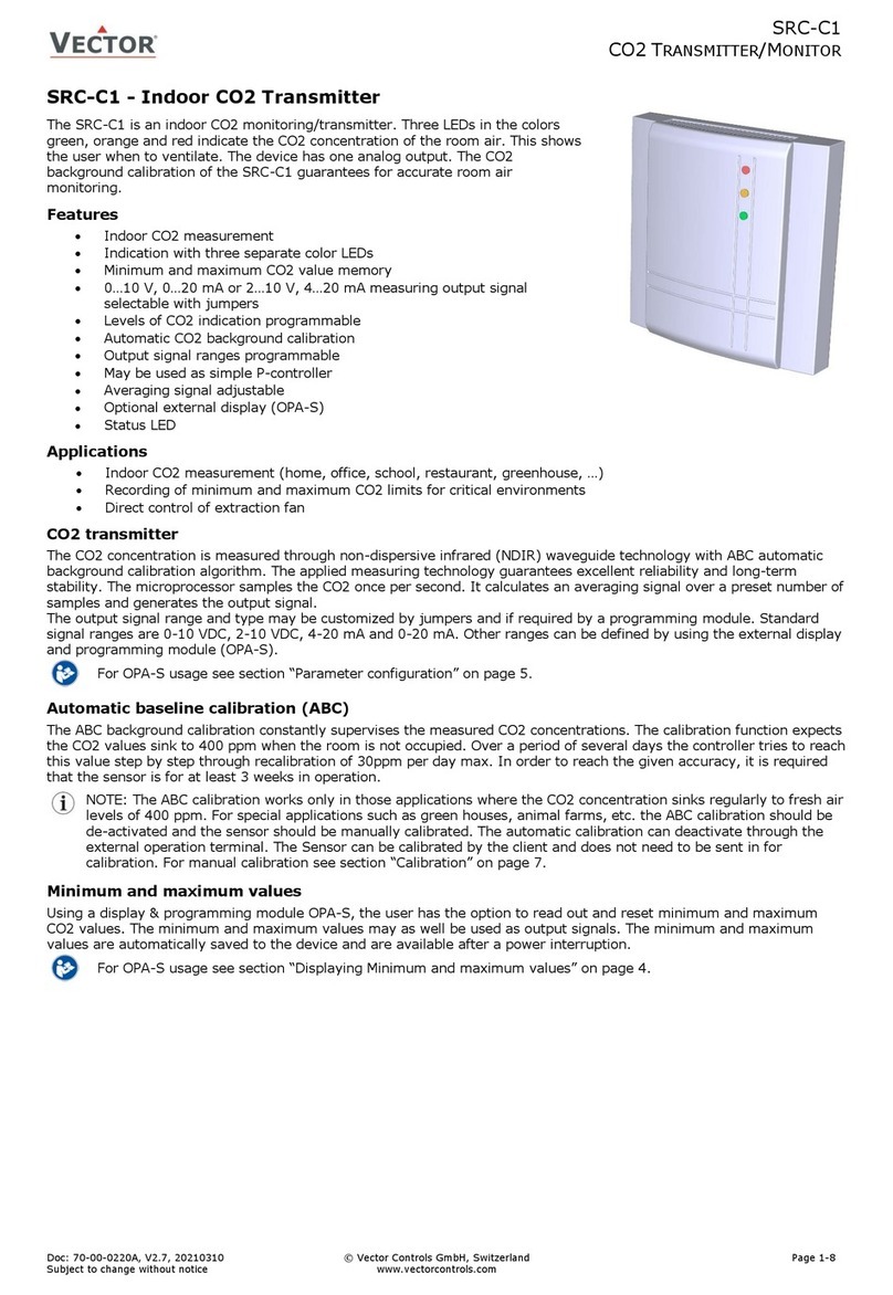
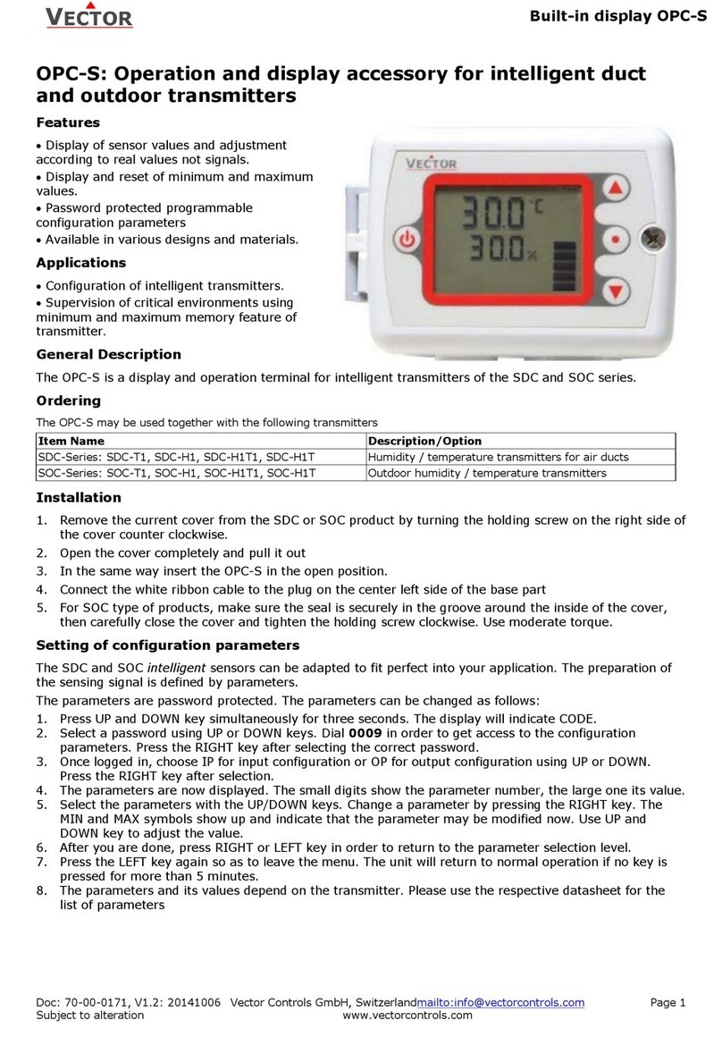
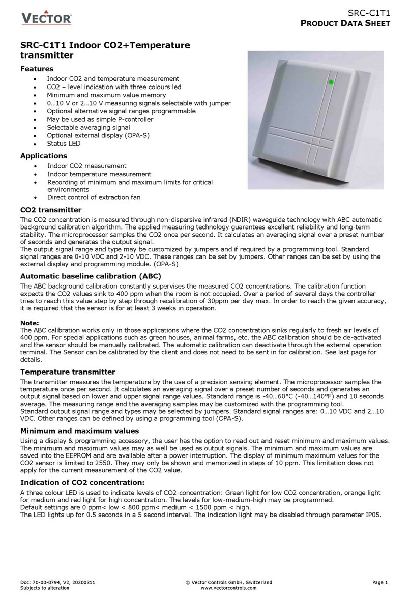
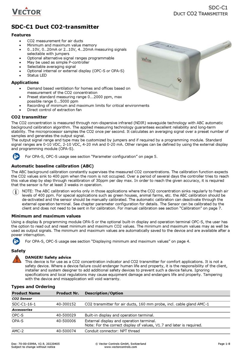
Vector SCC-T1-Tp2 Operational manual

SCC-T1-Tp2(-OP) for PT1000 probes
Product Data Sheet
Doc: 70-07-0175B, V1.0, 20210326 © Vector Controls LLC, USA Page 1-6
Subjects to alteration www.vectorcontrols.com
VECTOR
SCC-T1-Tp2 Temperature transmitter for PT1000 probes
Features
•Precision temperature measurement for different ranges and
accuracies
•Minimum and maximum value memory
•0…10V, 0…20mA or 2…10V, 4…20mA measuring signals,
selectable with jumpers
•Optional alternative signal ranges programmable
•Selectable averaging signal
•Optional LCD display (OPC-S) or external display (OPU-S)
•Status LED
Applications
•For indoor, outdoor, duct, immersion temperature
measurement for heating, ventilation and air conditioning
applications
•Recording of minimum and maximum values for critical environments
•Supervision of critical temperatures
Temperature transmitter
The transmitter measures the temperature for a PT1000 platinum film element. The transmitter does not include the
PT1000 sensor. An external PT1000 according to EN 60751 has to be connected for the transmitter to operate.
The microprocessor samples the temperature once per second. It calculates an averaging signal over a preset number of
seconds and generates an output signal based on lower and upper signal range values. Standard range is
-40…400°C (-40…752°F) and 1 second’s average.
The output signal range and type may be customized by jumpers and if required by a programming tool. Standard signal
ranges are 0-10VDC, 2-10VDC, 4-20mA and 0-20mA. These ranges can be set by jumpers. Other ranges can be set on the
–OP transmitter or by connecting OPU-S.
Minimum and maximum values
By using a display module (-OP or OPU-S), the user has the option to read out and reset minimum and maximum values.
The minimum and maximum values may as well be used as output signals. The minimum and maximum values are saved
into a non-volatile memory and are therefore available after a power interruption.
Types and Ordering
Part Name
Part No.
Measuring Temperature Range
Options
SCC-T1-Tp2
40-300075
-40…400°C (-40…752°F)
SCC-T1-Tp2-OP
40-300076
-40…400°C (-40…752°F)
Includes display module OPC-S
Accessories
Part Name
Part No.
Description
S-Tp2-2
40-200012
Flying lead sensor, 2 m cable
SD-Tp2-12-2
40-200024
Flying lead duct sensor; Probe length 12 cm, 2 m cable
SD-Tp2-20-2
40-200027
Flying lead duct sensor; Probe length = 20 cm, 2 m cable
SDB-Tp2-12
40-200056
Duct sensor, Probe length 12 cm
SDB-Tp2-20
40-200034
Duct sensor, Probe length 20 cm
SRA-Tp2
40-200041
Indoor sensor
SOD-Tp2
40-200064
Outdoor sensor
OPU-S
40-500030
External display module
AMC-1
20-100035
Cable gland PG9 for cables 4 –8 mm (AWG 6 –1)
AMC-2
20-100067
Conduit connector NPT 1/2

SCC-T1-Tp2(-OP) for PT1000 probes
Product Data Sheet
Doc: 70-07-0175B, V1.0, 20210326 © Vector Controls LLC, USA Page 2-6
Subjects to alteration www.vectorcontrols.com
VECTOR
Technical Specification
Important notice and safety advice
This device is for use as a temperature transmitter. It is not a safety device. Where a device failure could endanger human
life and property, it is the responsibility of the client, installer and system designer to add additional safety devices to
prevent such a device failure. Ignoring specifications and local regulations may cause equipment damage and endangers life
and property. Tampering with the device and misapplication will void warranty.
Power Supply
Operating Voltage
24 V AC 50/60 Hz ± 10%, 24VDC ± 10%
Power Consumption
Max 2 VA
Internal rectification:
Signal ground = power ground
Half wave rectified
Security transformer required
Connection
Terminal Connectors
For wire 0.34…2.5 mm2(AWG 24…12)
Signal Inputs
Sensing Element
PT1000 EN 60751
Signal Outputs
Output Signal
Resolution
Maximum Load
DC 0-10V or 0…20mA
10 Bit, 9.7 mV, 0.019.5 mA
20 mA, 500
Environment
Operation
Climatic Conditions
Temperature
Humidity
To IEC 721-3-3
class 3 K5
0…70°C (32…158°F)
<95% R.H. non-condensing
Transport & Storage
Climatic Conditions
Temperature
Humidity
Mechanical Conditions
To IEC 721-3-2 and IEC 721-3-1
class 3 K3 and class 1 K3
-40…80°C (-40…176°F)
<95% R.H. non-condensing
class 2M2
Standards
conformity
EMC Directive
Low Voltage Directive
2004/108/EC
2006/95/EC
Product standards
Automatic electrical controls for household
and similar use
Special requirement on temperature
dependent controls
EN 60 730 –1
EN 60 730 –2 - 9
Electromagnetic compatibility for
industrial and domestic sector
Emissions: EN 60 730-1
Immunity: EN 60 730-1
Degree of Protection
IP64 to EN 60 529
Safety Class
III (IEC 60536)
General
Housing Materials
PC+ABS (UL94 class V-0)
Dimensions (H x W x D):
Transmitter case
68 x 91 x 47mm (2.7 x 3.7 x 1.9 in)
Weight (including package)
SCC-T1-Tp2 : 185g (6.5 oz)
SCC-T1-Tp2-OP : 215g (7.6 oz)
Dimension [mm](in)
47 (1.9)
91 (3.6)
68(2.7)

SCC-T1-Tp2(-OP) for PT1000 probes
Product Data Sheet
Doc: 70-07-0175B, V1.0, 20210326 © Vector Controls LLC, USA Page 3-6
Subjects to alteration www.vectorcontrols.com
VECTOR
Installation
The transmitter should be installed, probe facing down, directly on the wall, in weather protected area.
1. Turn the single screw on the cover counter clockwise and remove cover.
2. Mark the location for the mounting holes on the wall.
3. Depending on the wall material, drill two holes for plugs or use self-tapping screws.
4. Mount the transmitter flat on a wall in a weather protected area. The cable glands or conduit connectors must face
downwards.
5. Connect the conductors to the terminals according to wiring diagram.
6. While in the open position, slide the two hooks of the cover into the latch at the left side of the back part.
7. Close the front part.
8. Tighten the single screw on the cover clockwise to secure the cover to the back part. There is no need to tighten
the screw too much.
Connection terminals
1: G Power supply 24VAC, +24VDC
2: G0 Power supply 0VAC, -24VDC
3: U1 JP1 = 1-2, voltage output of temperature transmitter 0…10V or 2…10V (JP2)
3: I1 JP1 = 2-3, current output of temperature transmitter 0…20mA or 4…20mA (JP2)
4: GM1 Negative power supply for external sensing element
5: M1 Negative measuring input for external sensing element
6: B1 Positive measuring input for external sensing element
7: GB1 Positive power supply for external sensing element
4-wire vs. 2-wire sensor
PT1000 measurement allows precise temperature measurement through a temperature dependent resistor. Any connection
wire, especially if they have a certain length, will add (and thus falsify) the measured resistance. It is therefore suggested,
in order to keep accuracy, to connect a 4-wire sensor to the transmitter when cables are longer than a very few meters. In
case of a 4-wire sensor, JP3 must be placed in position 2-3. When connected with only 2 wires, then these 2 jumpers must
be set to 1-2.
Output signal configuration
The analog output signal type may be configured with a jumper for 0-10 VDC or
0-20 mA control signals. The jumpers are located next to the terminal connector
of each analog output. See table below for jumper placement. The factory setting
is to 0-10 VDC.
The signal range may be set with JP2 for both analog outputs. JP2 will only
operate if the output range specified with OP01 and OP02 is left at the default
position of 0…100%. With any other setting the position of JP2 has no influence
and the range defined with the output parameters applies.
Signal Type
JP1
0 –10 V
(1-2)
0 –20 mA
(2-3)
Signal Range
JP2
0 –10 V, 0 –20 mA
(1-2)
2 –10 V, 4 –20 mA
(2-3)
0VAC
-24VDC
24V ADC
1
G
SCC-T1-Tp2
2
G0
3
U1/I1
T out
5
M1
RT1
6
B1
RT2
4
GM1
RT1-
7
GB1
RT2+

SCC-T1-Tp2(-OP) for PT1000 probes
Product Data Sheet
Doc: 70-07-0175B, V1.0, 20210326 © Vector Controls LLC, USA Page 4-6
Subjects to alteration www.vectorcontrols.com
VECTOR
Jumper settings
JP3/JP4 Sensor connection (Jumpers must match)
JP2 Signal range
U1: 2-10V
I1: 4-20mA
U1: 0-10V
I1: 0-20mA
3
2
1
3
2
1
JP1 Signal type
I1
0-20mA, 4-20mA
U1
0-10V, 2-10V
3
2
1
3
2
1
JP1
JP2
OPC-S
Status LED
LED indicates status
No light: no power or product damaged
Period: 2.5 seconds
1 Flash: Normal
2 Flashes: AO (Voltage) is shorted
3 Flashes: PT1000 input is open/disconnected
4 Flashes: PT1000 input is short
>=5 Flashes: HW Error
OPU-S
STATUS
LED
JP3/JP4
4-Wire connection
Compensate wire resistance
2-Wire connection
Wire resistance not compensated
3
2
1
3
2
1
1
2
3
4
G 24V
G0 0V
U1/ I1 AO T
5
6
7
GM1 RT1-
M1 RT1
B1 RT2
GB1 RT2+

SCC-T1-Tp2(-OP) for PT1000 probes
Product Data Sheet
Doc: 70-07-0175B, V1.0, 20210326 © Vector Controls LLC, USA Page 5-6
Subjects to alteration www.vectorcontrols.com
VECTOR
Configuration of SCC-T1-Tp2-OP or SCC-T1-Tp2
In order to configure the SCC transmitter or access minimum and maximum settings either the SCC-T1-Tp2-OP has to be
used or an OPU-S remote terminal need to be connected.
Display and operation
Legend:
1. 4-digit display of current value, Minimum, Maximum or
control parameter
2. Unit of displayed value, °C, °F, % or none
3. Graphical display of output or input signal with a
resolution of 10%
4. 4-digit display of current value or control parameter
5. Left bar = display of minimum value
Right bar = display of maximum value
LEFT key:
Exit from parameter menu
UP key:
Display Maximum values, press for more than 2 seconds resets Maximum value
DOWN key:
Display Minimum values, press for more than 2 seconds resets Minimum value
RIGHT key:
Select transmitter, For transmitters with more than one input.
Error messages
Following error condition may be displayed:
Err1: Communication time out between terminal unit and transmitter. Terminal unit will reset after 10 seconds.
Err2: Temperature sensor faulty. The connection to the temperature sensor may be interrupted or the temperature
sensor is damaged
Indication and reset of minimum and maximum values
Press UP to display Maximum values, press DOWN key to display minimum values.
Resetting minimum or maximum values: Pressing either UP or DOWN keys for longer than 3 seconds while the minimum or
maximum values are displayed.
Configuration parameters
The SCC intelligent sensors can be adapted to fit perfect into your application. The preparation of the sensing signal is
defined by parameters.
The parameters are password protected. The parameters can be changed as follows:
1. Press UP and DOWN key simultaneously for three seconds. The display will indicate CODE.
2. Select a password using UP or DOWN keys. Dial 09 in order to get access to the configuration parameters. Press
the RIGHT key after selecting the correct password.
3. Once logged in, choose IP for input configuration or OP for output configuration using UP or DOWN. Press the
RIGHT key after selection.
4. The parameters are now displayed. The small digits show the parameter number, the large one its value.
5. Select the parameters with the UP/DOWN keys. Change a parameter by pressing the RIGHT key. The MIN and MAX
symbols show up and indicate that the parameter may be modified now. Use UP and DOWN key to adjust the value.
6. After you are done, press RIGHT or LEFT key in order to return to the parameter selection level.
7. Press the LEFT key again so as to leave the menu. The unit will return to normal operation if no key is pressed for
more than 5 minutes.
Input configuration
Parameter
Description
Range
Default
IP 00
TI1: Celsius or Fahrenheit, C = OFF, F = ON
ON, OFF
OFF
IP 01
TI1: Samples taken for averaging control signal
1…255
1
IP 02
TI1: Calibration
-10…10
0.0
IP 03
TI1: Minimum temperature
-40…400°C (752°F)
-40 °C
IP 04
TI1: Maximum temperature
-40…400°C (752°F)
400°C
Output configuration
Parameter
Description
Range
Default
OP 00
AO1: Configuration of output signal:
0 = Feedback temperature input,
1 = Feedback temperature minimum value
2 = Feedback temperature maximum value
0 –2
0
OP 01
AO1: Minimum limitation of output signal
0 –Max %
0%
OP 02
AO1: Maximum limitation of output signal
Min –100%
100%
2

SCC-T1-Tp2(-OP) for PT1000 probes
Product Data Sheet
Doc: 70-07-0175B, V1.0, 20210326 © Vector Controls LLC, USA Page 6-6
Subjects to alteration www.vectorcontrols.com
VECTOR
Smart Sensors and Controls
Made Easy!
Quality - Innovation –Partnership
Vector Controls LLC
17, Francis J. Clark Circle
Bethel, CT 06801
USA
www.vectorcontrols.com/
This manual suits for next models
3
Table of contents
Other Vector Transmitter manuals
Popular Transmitter manuals by other brands

Altronics
Altronics A 1107A operating instructions

Dwyer Instruments
Dwyer Instruments 604D-0 Specifications-installation and operating instructions

FONESTAR
FONESTAR FO-469-TX instruction manual

Fly Sky
Fly Sky FS-i6 Setup

Intempco
Intempco RT610Di instruction manual

Echotouch
Echotouch FLOWLINE US01 Series manual