manuals.online logo
Brands
  1. Home
  2. •
  3. Brands
  4. •
  5. GE
  6. •
  7. Transmitter
  8. •
  9. GE Ericsson MASTR II Manual

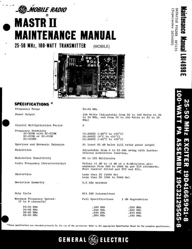
GE Ericsson MASTR II Manual

LBI-31985A
Printed in U.S.A
DESCRIPTION AND MAINTENANCE
851-870 MHz, 100 WATT MASTR II
STATION TRANSMITTER
19D901841G2
DESCRIPTION
The 851-870 MHz, 100 Watt MASTR II transmitter is a
crystal controlled, phase modulated transmitter designed for
single frequency operation. The transmitter utilizes both in-
tegrated circuit (ICs) and discrete components and consists
of the following modules:
•Exciter Board; with audio, modulator, amplifier and
multiplier stages.
•Power Amplifier; with or without Antenna Relay.
Figure 1 is a Block Diagram of the 851-870 MHz
MASTR II transmitter, showing the exciter, and the Power
Amplifier assemblies.
The Exciter contains the ±1 PPM Integrated Circuit Os-
cillator Module (ICOM), audio processor, modulator and
multipliers to provide the station operating frequency.
The PA assembly uses 3 RF amplifier stages to drive a
two transistor power output circuit. Each stage employs
matching networks consisting of discrete components and
strip line technology. The RF output power is fed to the an-
tenna through a circulator containing a low pass filter.
The PA assembly includes a power control module. The
power control module permits adjusting the power output
over a range of 10 to 100 watts. R11 located on the power
control board sets the output level. Three additional adjust-
ments are located on the control board: R2, RS, and R8.
These adjustments are not used in GE MARC applications.
The power adjust must be set for rated output only.
CAUTION
TABLE OF CONTENTS
Page
DESCRIPTION . . . . . . . . . . . . . . . . . . . . . . . . . . . . . . . . . . . . . . . . . . . . . . . Front Cover
MAINTENANCE . . . . . . . . . . . . . . . . . . . . . . . . . . . . . . . . . . . . . . . . . . . . . . 1
Dissassembly . . . . . . . . . . . . . . . . . . . . . . . . . . . . . . . . . . . . . . . . . . . . . 1
Alignment Procedure . . . . . . . . . . . . . . . . . . . . . . . . . . . . . . . . . . . . . . . . . 3
Troubleshooting Procedure . . . . . . . . . . . . . . . . . . . . . . . . . . . . . . . . . . . . . . 4
ILLUSTRATIONS
Figure 1 - Block Diagram . . . . . . . . . . . . . . . . . . . . . . . . . . . . . . . . . . . . . . . . . . 1
Figure 2 - Correction Factor Chart . . . . . . . . . . . . . . . . . . . . . . . . . . . . . . . . . . . . . 2
A directional coupler is used to monitor the output power.
The coupler output voltage is compared with the output of U1
which in turn controls the collector voltage of driver stages Q1
and Q2. The coupler voltage can be used as a power output
level indication when properly calibrated. The feedthrough ca-
pacitor CS located on W3A1 is a convenient place to measure
the control voltage.
MAINTENANCE
DISASSEMBLY
For a more complete mechanical parts breakdown, refer to
the station MAINTENANCE MANUAL.To service the trans-
mitter exciter from the front of the station:
1. Turn the two latching knobs on the front of the radio
housing counterclockwise to unlatch the radio hous-
ing front door.
2. Swing the door down.
3. Remove cover from the radio housing.
To remove Exciter Board:
1. Unplug the cables P101 and J902 from the exciter.
2. Remove the four screws and two stand-offs holding
the exciter board to the mounting frame and gently lift
the exciter board out of the radio.
Power Amplifier Assembly Removaland
Replacement PAAssembly Removal and Replacement
To remove PA assembly:
1. Disconnect the PA RF input cable from J1.
2. Disconnect the Antenna cable from J2.
3. Disconnect the Red and Black DC input power
leads.
4. Remove the six screws securing the PA Assembly
to the rack and remove thePA assembly.
To replace the PAassembly, perform the above procedure
in reverse order.
MODULATION LEVEL
ADJUSTMENT
The MOD ADJUST control (R1 03) was adjusted to the
proper setting before shipment and should not normally re-
quire readjustment. This setting permits approximately 75
percent modulation for the average voice level. The audio
peaks which would cause overmodulation are clipped by the
modulation limiter. The limiter, in conjunction with the de-
emphasis network, instantaneously limits the slope of the
audio wave to the modulator, thereby preventing overmodu-
lation while preserving intelligibility.
TEST EQUIPMENT
1. An audio oscillator (GE Model 4EX6A10)
2. A frequency modulation monitor
3. Voltmeter
4. GE Test Set Model 4EX3A11 or 4EX8K12
5. Frequency Counter
6. Oscilloscope
7. 50 ohm Wattmeter
PROCEDURE
1. Connect the audio oscillator and the meter across
audio input terminals J10 (Green-Hi) and J11
(Black-Lo) on GE Test Set, and connect red Test
Set plug to the System red metering plug. If not us-
ing GETest Set, connect audio oscillator and meter
across P902-6 (Mike-High) through 0.5 microfarad
(or larger) DC blocking capacitor, and P902-5
(Mike-Low) on the System Board.
2. Adjust the audio oscillator for 1 Volt RMS at 1000
Hz.
3. For NPSPAC transmitters without Channel Guard
set MOD ADJUST R103 for ±4.0 kHz deviation.
4. For NPSPAC transmitters with Channel Guard, set
MOD ADJUST R103 for ±3.25 kHz deviation and
set Channel Guard MOD ADJUST R102 for ±0.75
Hz tone deviation.
Type R103 R102
Non
Channel Guard ±4.5 kHz
Channel Guard ±3.7 kHz ±0.75 kHz
NPSPAC, Non
Channel Guard ±4.0 kHz
NPSPAC,
Channel Guard ±3.25 kHz ±0.75 kHz
ICOM FREQUENCY ADJUSTMENT
First, check the frequency to determine if any adjustment
is required. The frequency should be set with a frequency
meter or counter with an absolute accuracy that is 5 to 10
times better than the tolerance to be maintained, and with the
entire radio as near as possible to an ambient temperature of
27.5°C (81.5°F).
Copyright © May 1988, General Electric Company
Figure 1 - Block Diagram
Component placement and connections on the printed
wire board are very critical on the PA. For this reason,
it is recommended that the entire PA assembly be re-
turned to the factory for servicing.
NOTE
The RF Power Transistors used in the transmitter
contain Beryllium Oxide, a TOXIC substance. If the
ceramic, or other encapsulation is opened, crushed,
broken, or abraded, the escaping dust may be haz-
ardous if inhaled. Be extremely careful to avoid
damaging transistors when working with thePA As-
sembly.
WARNING
LBI-31985 LBI-31985
1
MASTR II ICOMs should be reset only when the fre-
quency shows deviation in excess of the following limits:
A. ±0.2 PPM, when the radio is at 27.5°C (81.5°F)
B. ±1 PPM at any other temperature within the range of -
30°C to + 85°C (-22°F to + 185°F)
If an adjustment is required, pry up the cover on the top
of the ICOM to expose the trimmer, and use one of the fol-
lowing procedures:
If the radio is at an ambient temperature of 27.5°C
(81.5°F), set the oscillator for the correct operating fre-
quency.
If the radio is not at an ambient temperature of 27.5°C,
setting errors can be minimized as follows:
A. To hold the setting error to 0.1 PPM (which is consid-
ered reasonable for 1 PPM ICOMs):
1. Maintain the radio at 27.5°C (81.5°F) and set the
oscillator to desired frequency, or -
2. Maintain the radio at 27.5°C ( 10°C) and offset the
oscillator, as a function of actual temperature, by
the amount shown in the correction factor chart
(Figure 2).
For example: Assume the ambient temperature of
the radio is 18.5°C (65.4°F). At that temperature,
the curve shows a correction factor of 0.44 PPM.
(At 851 MHz, 1 PPM is 851 Hz. At 875 MHz, 1
PPM is 875 Hz.)
With an operating frequency of 851 MHz, set the oscilla-
tor for a reading of 374 Hz (0.44 x 851 Hz) higher than the
licensed operating frequency. If a negative correction factor
is obtained (at temperatures above 27.5°C), set the oscillator
for the indicated PPM lower than the licensed operating fre-
quency.
TRANSMITTERALIGNMENT
EQUIPMENT REQUIRED
1. GETest Set Model 4EX3A11 or Test kit 4EX8K12.
2. A 50 ohm wattmeter capable of dissipating 150
Watts connected to the output terminal of the PAas-
sembly.
3. A frequency counter.
PRELIMINARY CHECKS AND
ADJUSTMENTS
1. Place ICOM on Exciter Board (crystal frequency =
operating frequency •48).
2. For a large change in frequency or a badly mis-
aligned transmitter, preset all slugs to the top of the
coil form.
3. Set Z101 and Z102 to top of coil form.
4. Set both air variable capacitors to minimum capac-
ity (not meshed).
5. Connect the red plug on the GE Test Set to the Sys-
tem Board metering jack, and the black plug to the
Exciter metering jack. Set the polarity to +, and set
the range to the Test 1 position (1 Volt position for
4EX8K12) for all adjustments.
All adjustments are made with the transmitter keyed.
Unkey the transmitter between steps to avoid unnecessary
heating.
Figure 2 - Correction Factor Chart
LBI-31985 LBI-31985
2
ALIGNMENT PROCEDURE
STEP METER
POSITION TUNING
CONTROL METER
READING PROCEDURE
100 WATT PA
13. Terminate the output power J2 with a 50 ohm watt
meter capable of reading 150 watts.
14. Key the transmitter and set R11 (control board) for
100 watt output.
15. Read and record the DC voltage at feed through
cap C5. This reading can be used for future output
checks.
DO NOT EXCEED 100 watts of output power.
16. Using the test set connected to the Exciter
metering jack and the transmitter keyed, detune
Z102 10 percent from its peak reading. The output
PWR should remain constant at 100 watts. This
check insures ample operating margin.
17. Tune Z102 back to a peak reading on the test set.
Under no conditions should the Exciter be
tuned using the PA output as a level indicator.
The PA control circuits mask Exciter tuning
procedures.
NOTE
851-870 MHz, 100 WATT TRANSMITTER
Issue 2
ALIGNMENT PROCEDURE
STEP METER
POSITION TUNING
CONTROL METER
READING PROCEDURE
EXCITER
1. B
(PHASE MOD) L103, T101 See Procedure Tune L103 for maximum meter reading. Then tune
T101 for a dip (small) in meter reading.
2. C
(MULT-1) T102 and T103 See Procedure Tune T102 for maximum meter reading, then tune
T103 for a dip in meter reading.
3. D
(MULT-2) T104 and T105 See Procedure Tune T104 for maximum meter reading and then
tune T105 for a dip in meter reading.
4. F
(MULT-3) T106 and C157 See Procedure Tune T106 for maximum meter reading and then
tune C157 for a dip in meter reading.
5. G
(MULT-4) C159 and Z101 See Procedure Tune C159 for maximum meter reading, and then
tune Z101 for a dip in meter reading.
6. A
(REL OUTPUT) Z102 Maximum Tune Z102 for maximum meter reading.
7. B
(PHASE MOD) L103 Maximum Tune L103 for maximum meter reading.
8. C
(MULT-1) T101 and T102 Maximum In order, tune T101 and T102 for maximum meter
reading.
9. D
(MULT-2) T103 and T104 Maximum Tune T103 and then T104 for maximum metering
reading.
10. F
(MULT-3) T105 and T106 Maximum Tune T105 and then T106 for maximum meter
reading.
11. G
(MULT-4) C157 and C159 Maximum Tune C157 and then C159 for maximum meter
reading.
12. D
(INPUT DRIVE) Z101, Z102 Maximum Test set connected to Exciter metering jack. Then
alternately tune Z101 and Z102 for maximum
meter reading.
When aligning transmitter, proceed as in-
structed below. DO NOT retune a previously
tuned control unless specifically directed to
do so.
NOTE
LBI-31985 LBI-31985
3
TROUBLESHOOTING PROCEDURE
STEP 1 - QUICK CHECKS
METER
POSITION
GE TEST SET
PROBABLE DEFECTIVE STAGE
HIGH METER
READING LOW METER
READING ZERO METER READING
EXCITER
B
(PHASE MOD) Q102, Q103, T101 Q102, Q103, T101 ICOM Q102, Q103, T101, ICOM
C
(MULT-1) Q104, T103 T101, T102, Q104 T101, T102, Q104, T103
D
(MULT-2) Q105, T105 T103, T104, Q105 T103, T104, Q105, T105
F
(MULT-3) Q106, C155 Q106, T105, T106 Q106, T105, T106, L105
G
(MULT-4) Q107, Z101, Z102 Q107, C159, C157 Q107, C159, C157, Z101, Z102
A
(REL OUTPUT) Q107 Q107, C174, CR102, R154, R153
851-870 MHz, 100 WATT TRANSMITTER
Issue 1
LBI-31985 LBI-31985
4
This page intentionally left blank
LBI-31985 LBI-31985
5

This manual suits for next models

1

Other GE Transmitter manuals

GE MASTR II User manual

GE

GE MASTR II User manual

GE VT4930WDM Installation guide

GE

GE VT4930WDM Installation guide

GE Hart Druck RTX 1000H Series User manual

GE

GE Hart Druck RTX 1000H Series User manual

GE AquaTrans AT868 User manual

GE

GE AquaTrans AT868 User manual

GE XMT868 User manual

GE

GE XMT868 User manual

GE AquaTrans AT868 User manual

GE

GE AquaTrans AT868 User manual

GE DigitalFlow XGS868i Owner's manual

GE

GE DigitalFlow XGS868i Owner's manual

GE VT4010M Installation guide

GE

GE VT4010M Installation guide

GE DewPro MMY30 User manual

GE

GE DewPro MMY30 User manual

GE XGS868 Owner's manual

GE

GE XGS868 Owner's manual

GE T5000 Series User manual

GE

GE T5000 Series User manual

GE MDS TD220MAX User manual

GE

GE MDS TD220MAX User manual

GE Masoneilan 12420 Installation and operating manual

GE

GE Masoneilan 12420 Installation and operating manual

GE HygroTrace User manual

GE

GE HygroTrace User manual

GE UTX878 Ultrasonic User manual

GE

GE UTX878 Ultrasonic User manual

GE VT6010 Installation instructions

GE

GE VT6010 Installation instructions

GE XMTC User manual

GE

GE XMTC User manual

GE DewPro MMY31 User manual

GE

GE DewPro MMY31 User manual

GE Masoneilan 469 Series User manual

GE

GE Masoneilan 469 Series User manual

GE SSB Jr. User manual

GE

GE SSB Jr. User manual

GE PanaFlow XMT1000 User manual

GE

GE PanaFlow XMT1000 User manual

GE XMO2 User manual

GE

GE XMO2 User manual

GE MASTR II User manual

GE

GE MASTR II User manual

GE DewPro MMY31 User manual

GE

GE DewPro MMY31 User manual

Popular Transmitter manuals by other brands

Key Digital KD-HDMIWPTX operating manual

Key Digital

Key Digital KD-HDMIWPTX operating manual

hager I-EA00116 installation instructions

hager

hager I-EA00116 installation instructions

Crestron IM-TCCV Operation and installation guide

Crestron

Crestron IM-TCCV Operation and installation guide

Emerson Rosemount 3095 Reference manual

Emerson

Emerson Rosemount 3095 Reference manual

Bacharach MGS 550 installation guide

Bacharach

Bacharach MGS 550 installation guide

Vega VEGABAR 14 operating instructions

Vega

Vega VEGABAR 14 operating instructions

Audiovox PurSuit 09XR1Pr Programming guide

Audiovox

Audiovox PurSuit 09XR1Pr Programming guide

HumanTechnik RadioLight operating instructions

HumanTechnik

HumanTechnik RadioLight operating instructions

CYP CHDBT-1H3CE Operation manual

CYP

CYP CHDBT-1H3CE Operation manual

RHEONIK RHE26 Installation & start?up guide

RHEONIK

RHEONIK RHE26 Installation & start?up guide

BWI Eagle AIR-EAGLE XLT PLUS 497-5100-CHx-DC Product information bulletin

BWI Eagle

BWI Eagle AIR-EAGLE XLT PLUS 497-5100-CHx-DC Product information bulletin

Nulaxy KM28 user manual

Nulaxy

Nulaxy KM28 user manual

CDVI Erone TTH2641E1B quick start guide

CDVI

CDVI Erone TTH2641E1B quick start guide

Dejero EnGo 260 user guide

Dejero

Dejero EnGo 260 user guide

Nokeval MTR265B user manual

Nokeval

Nokeval MTR265B user manual

Siemens SITRANS L Series operating instructions

Siemens

Siemens SITRANS L Series operating instructions

Becker Centronic EasyControl EC242-II Assembly and operating instructions

Becker

Becker Centronic EasyControl EC242-II Assembly and operating instructions

SEBA KMT Sebalog GT-3-1 user manual

SEBA

SEBA KMT Sebalog GT-3-1 user manual

manuals.online logo
manuals.online logoBrands
  • About & Mission
  • Contact us
  • Privacy Policy
  • Terms and Conditions

Copyright 2025 Manuals.Online. All Rights Reserved.