General Monitors S214 User manual

ModelS214
Hydrogen Sulfide Gas
Enhanced Smart Sensor
(Single Point Calibration)
The information and technical data disclosed in this
document may be used and disseminated only for the
purposes and to the extent specifically authorized in
writing by General Monitors.
Instruction Manual 05/97
General Monitors reserves the right to change
published specifications and designs without prior
notice.
Part No MANFL3100/1
Revision E/11-99

WARRANTY STATEMENT
General Monitors warrants the Model S214
to be free from defects in workmanship or
material under normal use and service within
two (2) years from the date of shipment.
General Monitors will repair or replace
without charge any equipment found to be
defective during the warranty period. Full
determination of the nature of, and
responsibility for, defective or damaged
equipment will be made by General Monitors’
personnel. Defective or damaged equipment
must be shipped prepaid to General Monitors’
plant or the representative from which
shipment was made. In all cases this
warranty is limited to the cost of the
equipment supplied by General Monitors.
The customer will assume all liability for the
misuse of this equipment by its employees or
other personnel. All warranties are
contingent upon proper use in the application
for which the product was intended and do
not cover products which have been modified
or repaired without General Monitors’
approval or which have been subjected to
neglect, accident, improper installation or
application, or on which the original
identification marks have been removed or
altered. Except for the express warranty
stated above, General Monitors disclaims all
warranties with regard to the products sold,
including all implied warranties of
merchantability and fitness and the express
warranties stated herein are in lieu of all
obligations or liabilities on the part of General
Monitors for damages including, but not
limited to, consequential damages arising out
of/or in connection with the use or
performance of the product.
WARNINGS
lHYDROGEN SULFIDE GAS IS AN
EXTREMELY TOXIC GAS, AND
EXPOSURE MAY RESULT IN A LOSS
OF CONSCIOUSNESS OR DEATH.
lThe Model S214 Hydrogen Sulfide Gas
Smart Sensor assembly contains
components which can be damaged by
static electricity. Special care must be
taken when wiring the system to ensure
that only the connection points are
touched.
lIMPORTANT: Each H2S sensor
is shipped with a red plastic cap
fitted over the sensor head.
Inside the cap is a desiccant.
DO NOT remove this cap until
you are ready to power the
system. SAVE the cap and
RE-CAP the sensor anytime the
system power is off for more
than an hour.
i
GENERAL MONITORS
Model S214

Table of Contents
Warranty
Warning - Toxic Danger
Warning - Electrostatic Damage
1.0 Introduction
1.1 General Description
1.2 Features and Benefits
1.3 Applications
2.0 Sensor Assembly
2.1 Sensor Signal Processing
2.2 Power Supply
2.3 Control Electronics
3.0 Installation
3.1 Receipt of Equipment
3.2 Sensor Location Considerations
3.3 Installation Instructions
3.4 Terminal Connections
3.5 Applying Power
3.6 Maintaining the X/P Integrity
4.0 Operation
4.1 Calibration
4.2 Calibration Equipment
4.3 Test Gas Mode
4.4 Digital Display Codes
4.5 Fault Codes & Their Remedies
5.0 Appendix
5.1 Specifications
5.1.1 System Specifications
5.1.2 Mechanical Specifications
5.1.3 Electrical Specifications
5.1.4 Environmental Specifications
5.2 Engineering Documentation
5.2.1 Termination & Outline Drawings
5.2.2 Termination Drawing - CE Mark
Units 5.3 Ordering Information
5.4 FMRC Approval
5.5 Calibration Schedule for Problem Environ-
ments
Page #
i
i
i
1
1
1
3
4
4
5
5
6
7
10
10
11
12
13
14
14
17
17
17
17
18
19
19
21
22
23
24
ii
GENERAL MONITORS
Model S214

Table of Figures
Figure 1 MOS Sensor Diagram
Figure 2 Input Signal Circuit Flow Diagram
Figure 3 H2S Adsorption Diagram
Figure 4 Converter Electronics Flow Diagram
Figure 5 Control Electronics Flow Diagram
Figure 6 Overall and Mounting Dimensions
Figure 7 Conduit, Drain Loop, and Seal Drawing
Figure 8 Terminal Connections, TB1 and TB2
Figure 9 Wire Strip Length Diagram
Figure 10 Terminal Block Operation Drawing
Figure 11 4-20mA Output Signal Connections
Figure 12 Input Power Connections
Figure 13 GMI Logo and Display Window Drawing
Figure 14 Diagram, Automatic Calibration Sequence
Figure 15 CAL Bottle & Ampoule Diagram
Figure 16 Diagram of Test Gas Mode
Figure 17 Termination Drawing - S214
Figure 18 Outline and Dimensional Drawing - S214
Figure 19 Termination Drawing - CE Mark Units
Calibration Schedule for Problem Environments
Page #
3
3
3
4
4
6
7
7
8
8
9
9
11
12
13
13
19
20
21
24
iii
GENERAL MONITORS
Model S214

1.0 Introduction
1.1 General Description
The Model S214 is an Enhanced Smart Sensor
assembly that is used for detecting Hydrogen
Sulfide gas. The microprocessor based elec
-
tronics process information at the sensor site
and are contained within an explosion proof
housing. A digital display provides indica-
tions and display codes that can be viewed
through a window in the cover. An analog
signal (4-20mA) provides remote and/or dis
-
crete indications of the sensor’s operation.
The Model S214 Enhanced Smart Sensor As
-
sembly is rated explosion proof for use in
Class I, Division 1, Group B, C, and D haz-
ardous areas.
1.2 Features and Benefits
Microprocessor-Based Electronics: monitors
8 individual fault conditions, processes input
signals from the sensor and provides outputs
in the form of display codes, and an analog
signal.
One Person Single Point Calibration: initi
-
ate the calibration sequence with a magnet,
apply the gas, and wait for the display to indi
-
cate that the unit has completed the calibra-
tion. No tools or adjustments are required.
2 Digit Display: indicates gas concentrations,
fault codes, and calibration cues.
4 to 20 mA Output: transmits fault, over
range, calibration, and gas concentration lev
-
els to a remote display, computer or other de
-
vice.
1.3 Applications
This is a partial listing of applications.
lRefineries
lDrilling Platforms and Rigs
lGas and Oil Production Platforms
lMud-Logging Operations
lDesulfurization Facilities
lHeavy Water Nuclear Facilities
lWastewater Treatment Plants
lChemical and Petrochemical Plants
lWell Head Sites
lOil Recovery/Reinjection
1
GENERAL MONITORS
Model S214

2

2.0 Sensor Assembly
2.1 Sensor Signal Processing
General Monitors uses a proprietary Metal
Oxide Semiconductor (MOS) film on the
sensor for detecting hydrogen sulfide (H2S)
gas. The MOS film is deposited onto a
substrate between two electrodes (figure 1).
With no gas present, the measured resistance
between these two electrodes is very high (in
the mega-ohms). As H2S adsorbs onto the
film, the resistance between the two
electrodes decreases (to kilo-ohms). This
decrease in resistance is logarithmically
proportional to the concentration of H2S that
is present.
figure 1
The change in resistance is converted to a
change in voltage and amplified by the input
circuit (figure 2). This amplified signal is fed
to an Analog to Digital (A/D) Converter,
converted to a digital signal and sent to the
microprocessor to be processed. The process
of H2S adsorbing onto the MOS film is most
effective at an elevated temperature. On the
outer edge of the substrate is a heater ring.
figure 2
The temperature of this heater ring is
measured with a thermistor and kept constant
by a circuit located inside the body of the
sensor. As H2S adsorbs onto the film,
electrons move more freely from one
electrode to the other (figure 3). This is
represented as a decrease in resistance. The
process of H2S adsorbing onto the MOS film
is completely reversible. As the
concentration of H2S decreases (H2S
desorbs), the resistance between the
electrodes will increase.
figure 3
3
GENERAL MONITORS
Model S214

Sensor Assembly
2.2 Power Supply
The Model S214 operates from a +24VDC
(nominal) input. This unregulated source is
fed to a converter board that produces
voltages (see figure 4). These signals are the
source for operating all of the circuitry on the
control and the display boards, and supplying
the sensor with power. Terminal connections
inside of the housing have been provided for
accepting the input power.
2.3 Control Electronics
The control electronics are centered around an
eight bit microprocessor (figure 5). The
Sensor Signal, the CAL Switch, the
Non-Volatile Memory (NOVRAM), and
certain fault conditions are monitored as
inputs. By processing these inputs, the
following outputs are generated: 4-20mA
Analog Output Signal, Digital Display
Indications, and Calibration Values to the
NOVRAM.
As the microprocessor (MPU) receives and
processes the inputs, it determines what value
is output to the display and the 4-20mA
current generator. When the CAL Switch is
activated, the MPU allows the user to choose
between the Calibration and the Test Gas
modes. While the unit is in one of these
modes, the MPU will fix the 4-20mA output
signal to 1.5mA (0mA is signal optional for
the calibration mode only).
figure 4
figure 5
Calibration Mode: When the unit is placed
in this mode, the MPU will look at the signal
from the sensor and determine when to accept
the calibration value. This value is stored in
NOVRAM and is used to adjust the digital
potentiometers associated with the Input
Amplifier. During calibration the
microprocessor will output a 1.5mA analog
signal (0mA is optional).
Test Gas Mode: In this mode, the MPU will
output the gas concentration to the display.
When the gas concentration drops below 5%
of full scale, the unit will return to normal
operation. The purpose of this mode is to
check the response of the unit to a known
level of gas and determine if calibration is
necessary, while the output current remains at
1.5mA.
4
GENERAL MONITORS
Model S214

3.0 Installation
3.1 Receipt of Equipment
All equipment shipped by General Monitors
is prepackaged in shock absorbing containers
which provide considerable protection against
physical damage. The contents should be
carefully removed and checked against the
packing slip. If any damage has occurred or
if there is any discrepancy in the order, notify
General Monitors as soon as possible. All
subsequent correspondence with General
Monitors must specify the equipment part and
serial numbers.
Each Model S214 is completely checked by
the factory. However, a complete check-out is
necessary upon initial installation and start up
to ensure system integrity.
3.2 Sensor Location Considera
-
tions
There are no standard rules for sensor
placement since the optimum sensor location
is different for each application. The
customer must evaluate conditions at the
facility to make this determination.
Generally, the Model S214 Smart Sensor
should be easily accessible for calibration
checks. The sensor assembly should be
mounted pointing down to prevent water
build-up on the sensor head. The sensor
assembly should not be placed where it may
be coated by contaminating substances.
Although the Model S214 is RFI resistant, it
should not be mounted in close proximity to
radio transmitters or similar equipment.
lLocate the Model S214 where prevailing
air currents contain the maximum
concentration of gas.
lLocate the Model S214 near possible
sources of gas leaks.
lObserve the Model S214’s temperature
specification and locate the unit away
from concentrated sources of heat.
lSensor Assemblies should be mounted in
an area that is as free from wind, dust,
water, shock, and vibration as possible.
See Appendix, section 5.1.4 for the
environmental specifications of the unit.
Sensors may be adversely affected by
prolonged exposure to certain materials. Loss
of sensitivity or corrosion may be gradual if
such materials are present in low
concentrations, or it may be rapid at high
concentrations. The more important materials
adversely affecting sensors are:
lSilicones (often contained in greases and
aerosols). Silicones do not chemically
attack the sensor, they coat it and reduce
or inhibit its response to the presence of
H2S gas.
lHalides ... compounds containing fluorine,
chlorine, bromine, or iodine.
lCaustic and acidic liquids and vapors.
The presence of poisons and contaminants in
an area does not necessarily preclude the use
of a Model S214 Enhanced Smart Sensor. The
feasibility of using a sensor in such areas
must be determined by an analysis of the
specific factors in each application and
General Monitors should be consulted before
attempting any such installation.
5
GENERAL MONITORS
Model S214

Installation
Sensor location Considerations (continued)
Sensors used in these areas usually require
more frequent calibration checks than normal,
and typically have a shorter life. In many
such applications the normal two year
warranty would not apply.
IMPORTANT:
Each H2S sensor is shipped with a red plastic
cap fitted over the sensor head. Inside the cap
is a desiccant. DO NOT remove this cap until
you are ready to power the system. SAVE the
cap and RE-CAP the sensor anytime the
system power is off for more than an hour.
CAUTION:
General Monitors discourages the painting of
sensor assemblies. If the sensor head is
painted over, the gas will not be able to
diffuse into the sensor. If the assembly cover
is painted over, the digital display cannot be
read.
3.3 Installation Instructions
Once correctly installed, the Model S214
requires little or no maintenance other than
periodic calibration checks to ensure system
integrity. General Monitors recommends that
a schedule be established and adhered.
General Monitors recommends that the
complete system, including all alarm
circuitry, be tested at least annually.
The overall and mounting dimensions for the
Model S214 (figures 6 & 18) should be used
when making installation determinations. A
complete list of the mechanical specifications
can be found in the Appendix (section 5.1.2).
See pages 19 and 20 for dimensions and
outline drawing.
To prevent possible corrosion due to moisture
or water condensation entering the Model
S214 through the conduit, it is
recommended that the conduit be sealed
or contain a drain loop near the conduit
entry of the housing (figure 7). Each
conduit run from a hazardous location to
a non-hazardous location should be
sealed so that gases, vapors, and/or
flames can not pass beyond the seal.
The purpose of seals in a Class I
hazardous location is to prevent the
passage of gases, vapors, or flames from
one electrical installation to another
through the conduit system. However, it
is not necessary to seal the Model S214
housing in order to maintain its
explosion proof integrity. Specific
information on Class I location seals and
drainage can be found in the National
Electric Code handbook, Article 501-5.
6
GENERAL MONITORS
Model S214
figure 6

Installation
Installation Instructions (continued)
NOTE: Acetic acid will cause damage to
metal components, metal hardware,
ceramic IC’s, etc. If damage results from
the use of a sealant that outgases acetic
acid (RTV silicone), the warranty will be
void.
Sensor heads exposed to the elements may
require the accessory mounting threads to be
lubricated. Grease must not be used. As an
alternate, PTFE (teflon) tape may be used on
threads that do not contact the Sensor
Housing.
The removal of particulate matter from sensor
accessories may be done through the use of an
appropriate halogen-free solvent. Water or
ethanol are examples of suitable solvents. The
accessories should be thoroughly dried, with
compressed air if necessary, before refitting
to the sensor body.
Some typical items to check during
maintenance examinations are:
lThe sensor mounting, to see it is secure.
lThe sensor screen, to see it is clear of oil,
water, dust or paint which might clog it.
lThe cable connections for tightness and
possible damage.
lAll sensor placements are up to date with
the layout of the plant, e.g. modifications
to the plant.
lThe complete system, to see it has a back
up supply for the full prescribed time.
NOTE: The system’s full two year
warranty will be voided if customer
personnel or third parties damage the
system during repair attempts.
3.4 Terminal Connections
The terminal blocks (TB) are located inside of
the housing and can be accessed by removing
the cover (see figure 8). TB2 contains the
four sensor connections, White (W), Green
(G), Black (B), and Red (R). TB1 contains
the connections for Power and Output Signal
(CE Mark units, connections are made to TB4
- fig. 19, page 21).
GENERAL MONITORS
Model S214
7
figure 8
figure 7

Installation
Terminal Connections (continued)
CE Mark units see fig. 19, on page 21.
TB1 position Function
14-20mA Output
2NOT USED
3NOT USED
4NOT USED
5NOT USED
6Common (Ground)
7+24VDC Power
NOTE: Contact with PCB components
should be avoided to prevent damage by
static electricity. All wire connections are
made to the Terminal Blocks.
It is recommended that a three wire (red,
black, white) shielded cable be used for
making power and output signal connections
on the Model S214. The terminal block
accepts 16 AWG to 22 AWG stranded or
solid wire. Each wire should be stripped
before wiring the Model S214 Hydrogen
Sulfide (H2S) Gas Enhanced Smart Sensor.
NOTE: 14 AWG wire can be used if it is
carefully stripped (figure 9).
figure 9
To connect wiring to the terminal block,
insert a screw driver into the orange tab and
press down (figure 10), opening the terminal.
Insert the wire into the terminal and release
the orange tab, clamping the wire in the
terminal. Check the connection by GENTLY
tugging the wire to ensure it is locked in.
A 4 to 20mA output signal is provided by the
Model S214 Hydrogen Sulfide Gas Enhanced
Smart Sensor and can be sent up to 9000 feet
(2740 meters) to a General Monitors
readout/relay display module, industrial
analog to digital converter, computer based
monitor, PLC, DCS, etc. See the Appendix
(section 5.1.3) for cable length specifications.
The 4 to 20mA signal provides for control
room or other locations remote to the Model
S214 to display indications of operation and
alarm conditions. figure 10
GENERAL MONITORS
Model S214
8

Installation
Terminal Connections (continued)
To connect the 4 to 20mA output signal with
another unit, connect the white wire to TB1,
position 1 (CE Mark units - TB4, position 1),
labeled 4-20 mA OUT. For making output
signal connections to display devices, refer to
the specific manual for that device (figure
11).
figure 11
If a device other than a General Monitors
readout/relay display module is being used,
the commons, COM, of both systems must be
connected together.
The Model S214 Hydrogen Sulfide Gas
Enhanced Smart Sensor operates from a
nominal supply of +24 VDC. Primary DC
power must be provided by the customer
unless one of the following General Monitors
Modules is being used with the Model S214:
lDT210 Readout/Relay Display Module
with Power Supply & Relay Module
lDT230 Readout/Relay Display Module
lTA202A Trip Amplifier Module with a
PS002
The following General Monitors Modules
provide power connections for the Model
S214, but need a customer supplied DC
source (see Appendix, section 5.4):
lDT210 Readout/Relay Display Module
without Power Supply & Relay Module
lDT220 Dual Channel Display Module
lTA202A Trip Amplifier Module without a
PS002
Since the Model S214 is designed to operate
continuously, a power switch is not included,
in order to prevent accidental system
shut-down. NOTE: Power must remain
disconnected until all other wiring
connections have been made.
The maximum distance between the Model
S214 and the power supply is 4500 feet (1372
meters). See the Appendix (section 5.1.3) for
cable length specifications. The cable run
should be as short as possible.
To connect +24VDC to the Model S214,
connect the red wire to TB1, position 7 (CE
Mark units - TB4, position 2), labeled
+24VDC. Connect the black wire to TB1,
position 6 (CE Mark units - TB4, position 3),
labeled COM (figure 12).
figure 12
GENERAL MONITORS
Model S214
9

Installation
3.5 Applying Power
Before applying power to the system for the
first time, all wiring connections should be
checked for correctness and the housing cover
replaced. Upon first power-up the sensor may
take up to fifteen seconds to stabilize.
At the initial application of power, or after a
fault condition has been corrected, the unit
will indicate “SU” (Start-Up) before entering
the normal mode of operation.
General Monitors recommends that the Model
S214 be calibrated within the first hour of
operation after the initial application of power
and that a second calibration be performed 24
hours after this initial calibration. These two
calibration sequences should be performed
with new units and units that have been off of
power for more than a week. See Calibration,
section 4.1 for more details.
3.6 Maintaining the X/P Integrity
The Model S214 is rated explosion proof for
Class I, Division 1, Group B, C & D
hazardous locations. The acceptable limits
for explosion proof housings being used in
Class I hazardous locations are defined in
CSA Standard C22.2 No.30-M1986.
Anytime the cover of the smart sensor
housing is removed or the cover bolts are
loosened, the flame path between the lid and
the housing is effected. If power is left on
when removing or loosening the cover bolts
on the Model S214 it will be necessary to
de-classify the area. When replacing the
cover, the gap between the lid and the
housing should be less than .0015 inch
(.038mm).
This can be verified by tightening the cover
bolts to a torque setting of 50 inch-pounds or
by using a feeler gauge to ensure the gap
between the cover and the housing is less than
.0015 inch (.038mm).
There are four entry holes, one on each side
of the Model S214 housing. These holes are
dedicated to the sensor and conduit. Each
hole is tapped for 3/4 NPT threads. If a
particular entry hole is not used it must be
plugged during operation in the field. The
factory installs plugs in the unused entry
holes, except one. A plastic cap plug is
placed into this hole and must be removed
before conduit can be attached to the housing.
Each Model S214 will have the following
items placed in the remaining three entry
holes:
lA sensor, if present (if not, a plastic plug)
lTwo aluminum housing plugs
The sensor and aluminum housing plugs have
seven threads. Each of these components is
screwed into the housing using five to seven
turns. If it becomes necessary to replace one
of these components, the user must use five to
seven turns to ensure that the explosion proof
integrity of the housing is maintained.
GENERAL MONITORS
Model S214
10

4.0 Operation
4.1 Calibration
Activating the Calibration Switch will auto-
matically disable the alarm circuits by fixing
the analog output current to 1.5mA (0mA op
-
tional). When using a General Monitors dis
-
play module, this calibration current will
inhibit the alarm circuits and prevent sending
gas concentration information during the cali-
bration process.
General Monitors recommends that the
Model S214 Hydrogen Sulfide (H2S) Gas
Smart Sensor be calibrated one hour after and
twenty four hours after initial start-up, and
that calibration be checked at least every
ninety days to ensure the integrity of the sys
-
tem.
General Monitors is not implying that the cus-
tomer should expect problems with sensor life
or stability, but “frequent” calibration checks
merely ensure the integrity of the life protect
-
ing equipment.
The above statement is not intended to dis-
courage the customer from checking calibra
-
tion more frequently. Frequent calibration
checks are recommended for problem envi
-
ronments (i.e. mud collecting on the sensor
head, sensors accidentally being painted over,
etc, see Appendix 5.5).
NOTE: A calibration check consists of ap
-
plying a 50% of full scale concentration of
gas to the sensor and observing the reading
on the Model S214.
General Monitors recommends that a calibra
-
tion schedule be established and followed. A
log book should also be kept showing calibra-
tion dates and dates of sensor replacement.
Calibration Procedure:
lIf it is suspected that hydrogen sulfide gas
is present, it will be necessary to purge the
sensor with clean air.
lPlace the magnet over the GMI Logo on
the cover of the unit and hold it there until
“AC” appears on the display (about ten
seconds).
lApply a concentration of H2S gas,
equivalent to 50% of full scale, to the
sensor. The display will change from
“AC” to “CP” indicating that the sensor is
responding to the gas.
lAfter three to five minutes the display will
change from “CP” to “CC” indicating that
the calibration is complete. Remove the
calibration gas and allow the sensor to see
clean air. The display will indicate a few
parts per million and then drop to “0".
lThe unit is now calibrated and the new
values have been stored in the NOVRAM
(non-volatile memory).
11
GENERAL MONITORS
Model S214
figure 13

Operation
Calibration (continued)
General Monitors recommends that the Model
S214 be calibrated within the first hour of op-
eration after the initial application of power
and that a second calibration be performed 24
hours after this initial calibration. These two
calibration sequences should be performed
with new units and with units that have been
off of power for more than a week. Use the
calibration procedure listed on page 11.
Figure 14 shows a flow diagram of the codes
that will appear in the display window during
the calibration procedure.
The Model S214 can be re
-
turned to normal operation
if the magnet is re-applied
after ninety seconds of ini-
tiating the calibration se
-
quence. If the Model S214
is placed in the calibration
mode and no gas is applied
for twelve minutes, the unit
will revert to a fault condi-
tion. Placing the magnet
over the GMI Logo again
will return the unit to the
calibration mode.
Re-applying the magnet after ninety seconds
will return the Model S214 to normal opera
-
tion using the previous set of calibration val
-
ues.
If there is a problem and the Model S214 Hy
-
drogen Sulfide Smart Sensor cannot complete
the calibration sequence, the unit will display
a fault code and the analog output current will
drop to zero.
The Model S214 will indicate an “F1" if the
sensor is too responsive, an ”F3" if the sensor
is not sensitive enough, an “F2" if the total
calibration interval has been exceeded, or an
”F7" if the calibration values were not prop
-
erly stored in the NOVRAM. Other fault
codes are explained in section 4.5 Fault Codes
& Their Remedies.
NOTE: If the unit fails to calibrate an “F”
code will be displayed. The calibration gas
must be removed from the sensor, and the
sensor must see “clean” air for at least five
minutes before a second calibration is at-
tempted by re-applying the magnet. The
possible reasons for an unsuccessful cali
-
bration are covered in section 4.5 Fault
Codes & Their Remedies.
4.2 Calibration Equipment
General Monitors offers Breaker Bottles &
Ampoules as the method of introducing cali-
bration or test gas to the Model S214. It will
be necessary to place the ampoule in a breaker
bottle (see figure 15 on page 13). The am
-
poule should be 50% of full scale. Place the
breaker bottle over the sensor and put the unit
in the calibration mode (see “4.1 Calibra
-
tion”, page 11).
When the display indicates “AC” break the
50% of full scale ampoule. The display will
change to “CP” indicating that the sensor is
seeing the gas. When the display indicates
“CC”, remove the breaker bottle and allow
the sensor to see clean air.
figure 14
GENERAL MONITORS
Model S214
12

Operation
Calibration Equipment (continued)
Use the table below to determine 50% of full
scale for the different sensors.
Sensor Range (Type) 50% of Full Scale
0 to 100 ppm (‘-1’)50 ppm
0 to 50 ppm (‘-5’)25 ppm
0 to 20 ppm (‘-9’)10 ppm
(values given in parts per million)
figure 15
4.3 Test Gas Mode
If it is desired to check the sensor for its re
-
sponse without sending a gas concentration
signal to a remote display device, this can be
accomplished by placing the Model S214 in
the “Test Gas” mode.
The procedure for checking the calibration is:
lPlace the magnet over the GMI Logo on
the cover of the Model S214. Remove the
magnet when a flashing pair of bars, “-
-”, (figure 16) appears on the display
(about three seconds).
lApply the test gas to the sensor and the
value of the gas concentration will be
indicated by the flashing display in two to
three minutes. Note: applied gas
concentration must be >10% of full scale.
lWhen the reading has stabilized and the
test is complete, remove the gas and the
unit will return to normal operation when
the concentration drops below 5% of full
scale.
figure 16
If the Model S214 is placed in the test gas
mode and no gas is applied for twelve min
-
utes, the unit will revert to a fault condition
(see section 4.5 Fault Codes & Their Reme-
dies). Re-applying the magnet over the GMI
Logo will return the unit to normal operation.
During a calibration check, if the “test gas”
reading has stabilized and is out of tolerance,
the unit can immediately be placed in the
“calibration” mode by applying the magnet to
the General Monitors’ Logo on the lid of the
Model S214. NOTE: This should only be
done if a 50% full scale gas concentration was
applied.
13
GENERAL MONITORS
Model S214

Operation
4.4 Digital Display Codes
The following codes will appear on the dis
-
play when the unit is in a mode other than the
normal operating mode.
SU Start-up
- - (steady)Magnetic switch activated
- - (flashing)Test gas mode
AC Automatic calibration mode
CP Calibration in progress
CC Calibration is complete
or Over range
F1 High response to calibration gas
F2 Failed to complete the
calibration
F3 Low response to calibration gas
F4 Sensor heater is open circuited
F5 Sensor heater is short circuited
F6 Low Supply Voltage
F7 EEPROM verification failure
F8 NOT USED
F9 Calibration check period
exceeded
SU
This is displayed at start-up and after a Fault
condition has been corrected.
- -
Appears on the display when the magnet has
been properly positioned over the GMI Logo
and when the the Test Gas Mode can be
(steady) or has been (flashing) entered.
AC, CP, CC
These codes appear on the display during the
calibration process. For more information
about these codes, refer to section 4.1 Calibra-
tion.
F1, F2, F3, F4, F5, F6, F7, F9
These codes will appear on the display if a
Fault condition occurs. For more information
about these codes, refer to section 4.5 Fault
Codes & Their Remedies.
“or” (flashing)
This indicates that the concentration of hydro
-
gen sulfide gas exceeds the scale range of the
display (over range).
When the unit is in the normal operating
mode, the display will indicate the presence of
hydrogen sulfide gas in parts per million
(ppm). The ranges of detection are from 0 to
99ppm, 0 to 50ppm or 0 to 20ppm.
4.5 Fault Codes & Their Reme
-
dies
The Model S214 has self-diagnostics incorpo-
rated into the microprocessor’s program. If a
fault is detected, the output signal will drop to
0mA and a Fault code will be displayed. The
output signal will inform a remote display
module that the Model S214 is in Fault Mode.
The Model S214 will display an “F” code in
the display window at the sensor site.
There are eight Fault conditions that are moni
-
tored by the microprocessor. When a calibra
-
tion fault (F1, F2, F3) has occurred and has
been corrected, the unit will automatically re-
vert to the calibration sequence and the unit
must be re-calibrated. If a fault other than a
calibration fault occurs (F4, F5, F6, F7, F9),
and is corrected the unit will return to normal
operation.
GENERAL MONITORS
Model S214
1
4

Operation
Fault Codes & Their Remedies (continued)
The Fault Codes are:
F1 = High response during calibration
This fault may occur for one of the following
reasons:
lIncorrect gas concentration - If the applied
gas concentration is too high.
lFaulty sensor - A “-9" (0 to 20 ppm)
sensor is being used in a 0 to 100 ppm
application.
Take the appropriate action:
lMake sure that the gas concentration is
accurate.
lUse the correct sensor.
NOTE: If the unit fails to calibrate and an
F1 or an F3 code is displayed, the calibra-
tion gas must be removed from the sensor,
and the sensor must see clean air for at
least five minutes before a second calibra
-
tion is attempted.
F2 = Failed to complete the Calibration
This fault will occur if the unit is placed in the
calibration mode and the sensor has not re
-
sponded within twelve minutes.
F3 = Low response during calibration
This fault may occur for either of the follow
-
ing reasons:
lIncorrect gas concentration - If the applied
gas concentration is too low.
lFaulty sensor - The sensor may have
suffered a loss of sensitivity due to
contamination.
Take the appropriate action:
lMake sure that the gas concentration is
accurate.
lReplace the sensor.
F4 = Sensor heater is open circuited
This fault occurs if the sensor’s heater circuit
is open, or the sensor’s black and/or white
leads have become disconnected or broken.
Make sure the black and white sensor leads
are properly connected to the Terminal Block,
TB2. Replace the sensor, if necessary.
F5 = Sensor is short circuited
This fault occurs if the sensor heater switch
-
ing transistor short circuits.
Replace the sensor.
15
GENERAL MONITORS
Model S214

Operation
Fault Codes & Their Remedies (continued)
F6 = Low supply voltage
This fault occurs if the supply voltage drops
below +17VDC approximately.
Make sure that the supply voltage is at least
+20VDC at the Model S214.
NOTE: With long supply leads, a consider
-
able voltage drop may occur due to the
electrical resistance of the leads.
The maximum cable resistance which the
Model S214 can tolerate is 10 ohms per con
-
ductor (20 ohms loop) at +24 VDC minimum.
F7 = EEPROM verification failure
This fault occurs during calibration when an
attempt to verify the calibration parameter just
written to the non-volatile memory fails. The
usual cause of this is electrical interference
corrupting the data (although on rare occa-
sions it may indicate a problem within the
electronics module).
Place the magnet over the GMI Logo and ini
-
tiate another calibration.
F8 = NOT USED AT THIS TIME
F9 = Calibration check period exceeded
If the Model S214 is left in the Test Gas Mode
for more than twelve minutes without a test
gas being applied, this fault will occur.
Place the magnet over the GMI Logo to return
the unit to normal operation.
NOTE: Anytime a sensor is replaced, the unit
should be disconnected from all allarms, as
the unit may go upscale upon power-up.
GENERAL MONITORS
Model S214
1
6
Table of contents
Other General Monitors Accessories manuals

General Monitors
General Monitors S4000C User manual

General Monitors
General Monitors S104 User manual

General Monitors
General Monitors S4000T User manual

General Monitors
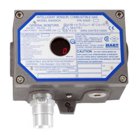
General Monitors S4000CH User manual

General Monitors
General Monitors 610 Use and care manual

General Monitors
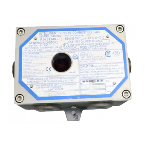
General Monitors S216A User manual