Ref 310087 Rev. A
08-17
KV SERIES
GENERAL PUMP A member of the Interpump Group
Page 10
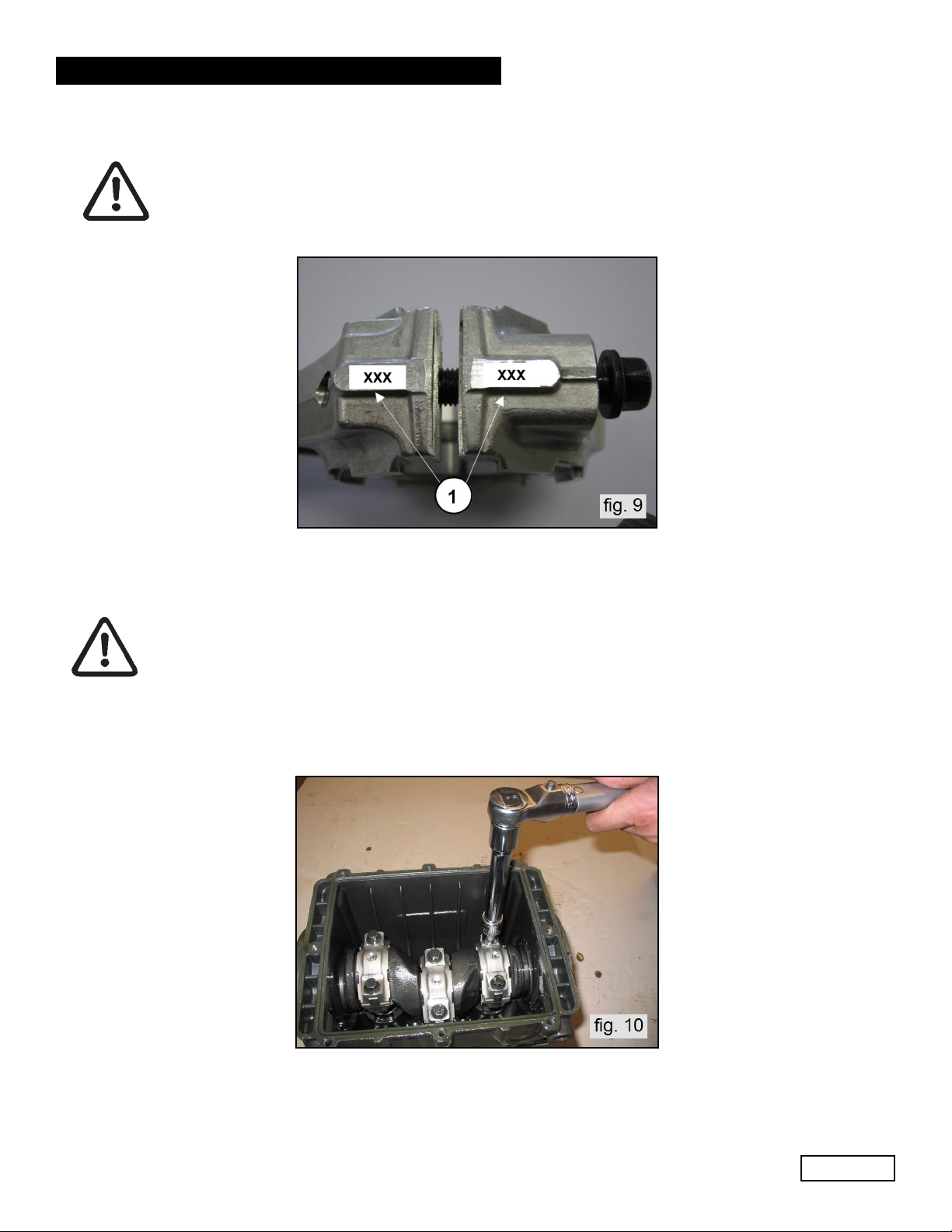
2.1.3 Reduction Classes
TABLE OF REDUCTION FOR CRANKSHAFT AND CON-ROD HALF-BEARINGS
Recovery classes
(mm)
Upper half-bearing
code
Lower half-bearing
code
Grinding on the shaft pin diameter
(mm)
0.25 F90922100 F90922400 Ø39.75 0/-0.02 Ra 0.4 Rt3.5
0.50 F90922200 F90922500 Ø39.50 0/-0.02 Ra 0.4 Rt 3.5
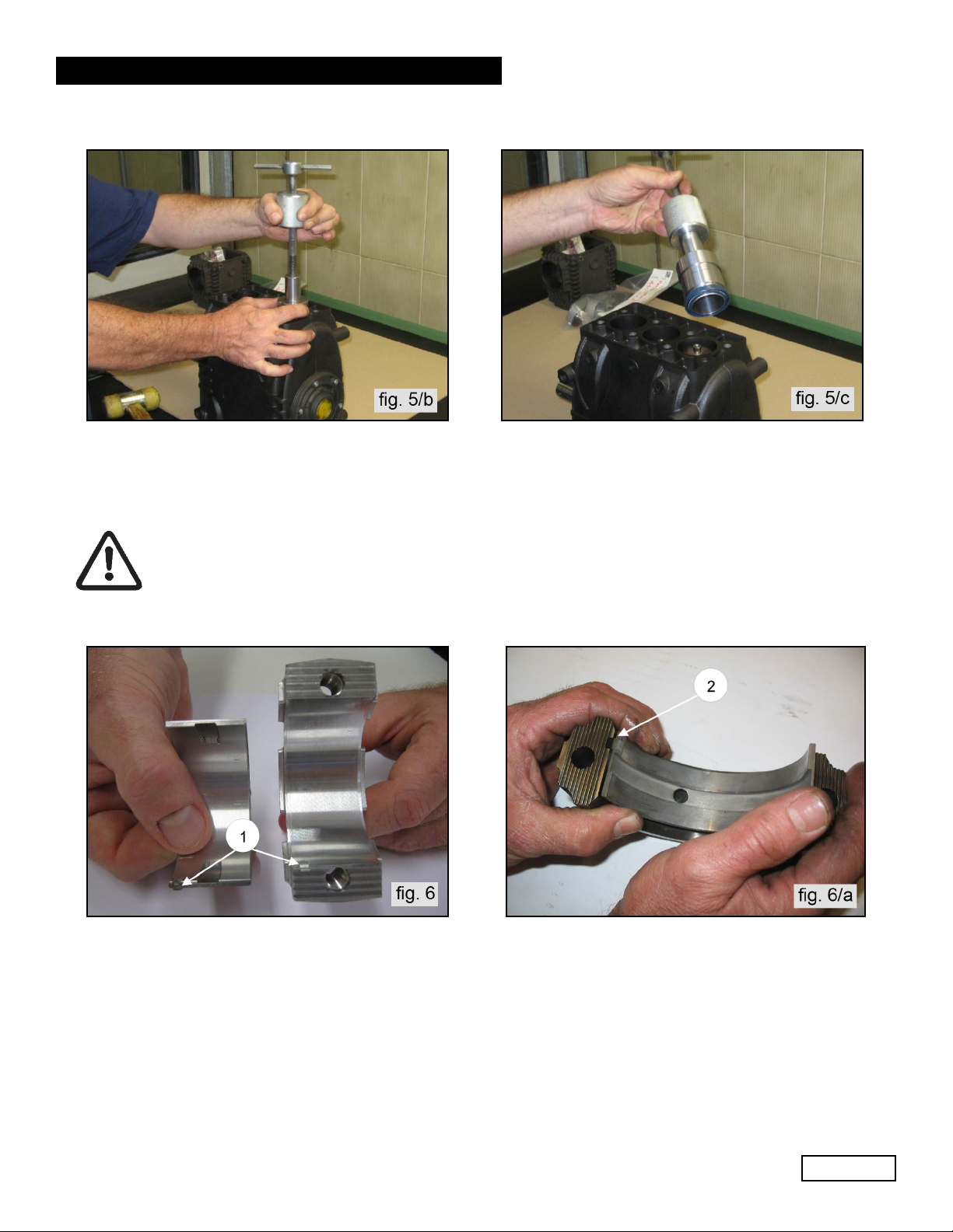
2.1.4 Assembly / Disassembly of bearings and shims
The type of bearings (taper roller) ensures the absence of axial clearance on the crankshaft. The shims are
defined to meet this necessity. For disassembly / reassembly and for any replacements, carefully observe the
following directions:
A) Assembly / Disassembly of the crankshaft without replacing the bearings
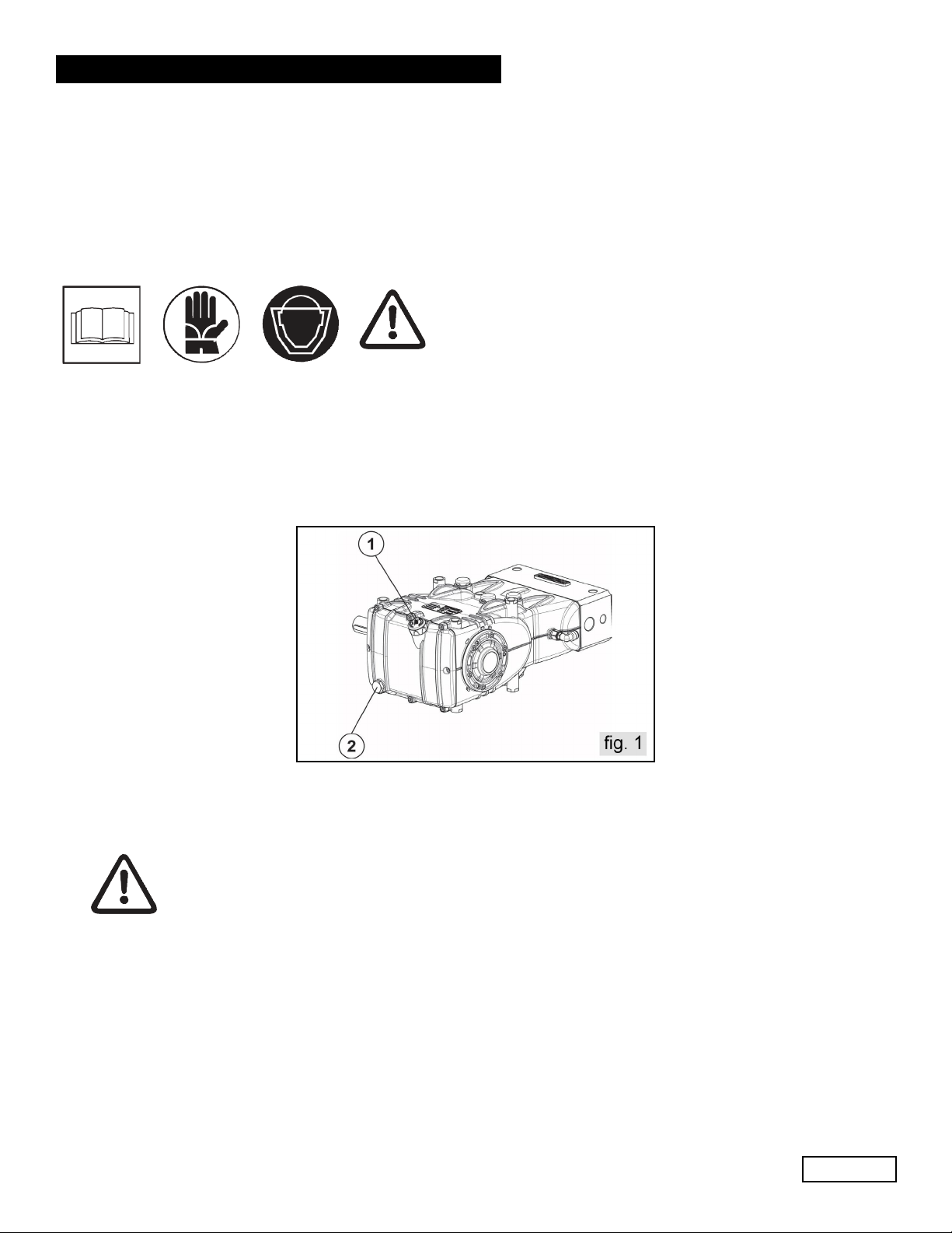
After removing the side covers, as indicated in paragraph 2.1.1, check the rollers and their races for wear; if
all parts are in good condition, fully clean the components with a suitable degreaser and grease them again
evenly using the same oil in the crankcase. The same shims can be used again, being careful to insert them
only under the indicator side cover. After installing the complete unit (sight glass side flange, shaft and engine
side flange), check that the shaft’s rolling torque - with the connecting rods free - is at least 3 Ft. Lbs. (4 Nm),
Max 4.5 Ft. Lbs. (6 Nm). To position the two side covers on the crankcase, initially use 3 M6 x 40 screws as
shown in fig. 8, and then the fastening screws. The shafts rolling torque (with connecting rods coupled must
not exceed 6 Ft. Lbs. (8 Nm).
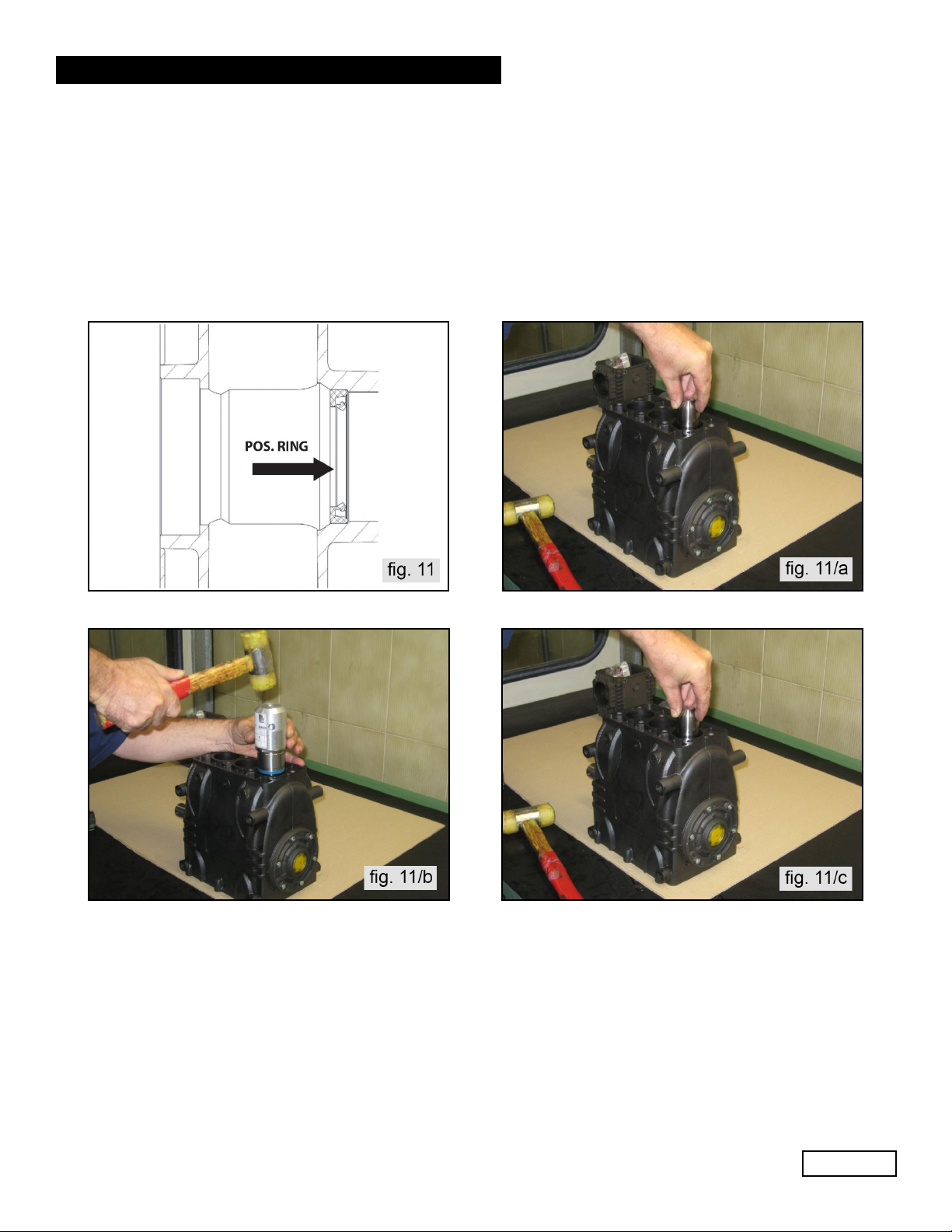
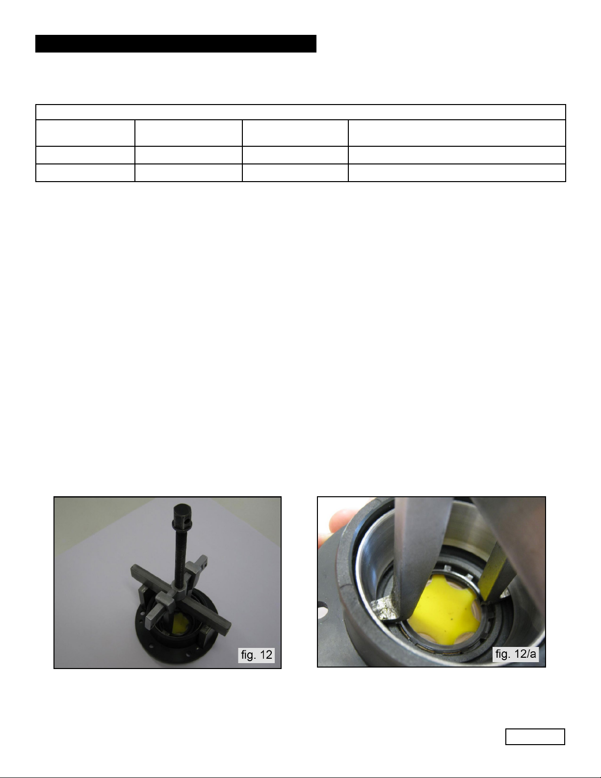
B) Disassembly / Assembly of the Crankshaft With Bearings Replacement
After disassembling the side covers as indicated in paragraph 2.1.1, remove the outer ring nut on the
bearings from its seat on the covers, using an appropriate exctrator as shown in (fig. 12 and 12/a).
Remove the inner ring nut on the bearings from the two ends of the shaft, again using an appropriate
extractor or, alternatively, a simple “pin punch” as shown in fig. 13.