General Sensors WIAR3 User manual

1
INSTRUCTION MANUAL
Model WIAR3 WIRELESS REPEATER
Contents of Package:
•(1) Wireless Repeater
•(4) 1” #6 Phillips head screws
•(4) Plastic anchor inserts
•(4) Molly bolts
Tools you will need:
•Phillips head screwdriver for #6 size screws
•Small awl
•Small hammer
•Magic marker
Other tools you may need:
•Drill w/ 3/16” masonry bit or 3/32” wood bit
for pilot holes when installing a Wireless
Repeater on masonry or wood.
Product Overview
•The model WIAR3, Wireless Repeater is a
wireless device that operates by receiving a
sensor’s coded signal and then transmitting
that signal to a receiver, greatly increasing
the effective range of the system. It will be
necessary to install a Wireless Repeater if
distance or interference is making it difficult
for a wireless sensor to communicate with
either a General Sensor’s Single Port or 4
Port Receiver. Under ideal conditions (no
interference from steel machinery or
cabinets and a clear line of sight between the
receiver and its corresponding sensor), a
Wireless Repeater can increase the effective
range of the receiver to more than 700 feet.
Please Note: For a typical installation, the
presence of steel cabinets, machinery,
electrical equipment, etc., will limit the
effective range of the system, even when
used in conjunction with a Wireless
Repeater.
1. Do I need a Wireless Repeater?
•Before you begin, make sure a Wireless
Repeater is necessary to solve the
communication problem between the
receiver and the sensor(s). The fastest way
to do this is to remove the sensor from the
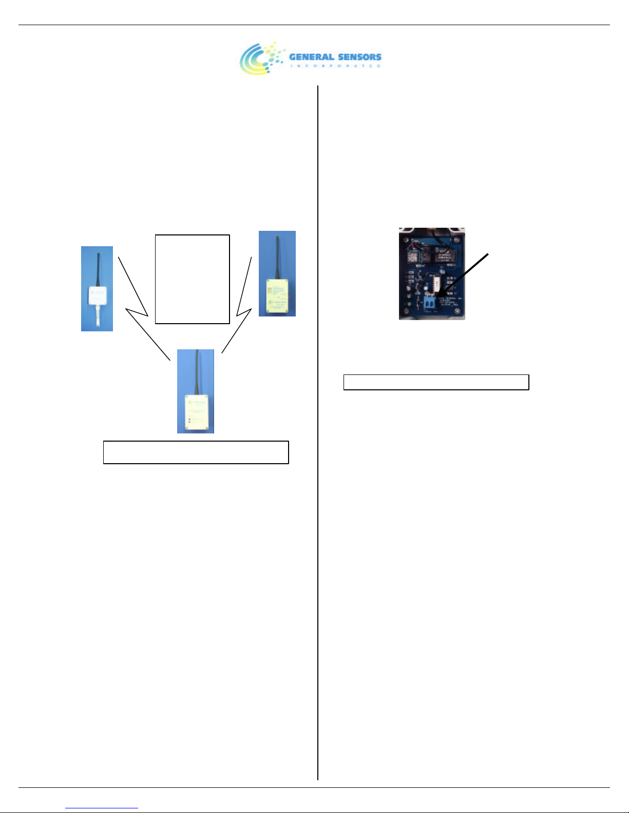
wall, bring it up close to its corresponding
receiver, and push the sensor’s blue Test
button at the bottom of the sensor’s printed
circuit board. If the DIP switch settings on
the sensor and receiver match, the receiver
should scroll through its LED display,
indicating a good communication link.
•If the receiver does NOT scroll through its
display, check the DIP switch settings on
both units. If the settings are not the same
you must change them so that they agree.
Make sure you remove the battery before
changing the DIP switch settings or the
micro-computer in the units will not
recognize the change. Once you change the
settings, push the red Reset button on the
receiver. Now bring the sensor up close to
the receiver and push the blue Test button
again to see if the receiver scrolls through its
display. A Wireless Repeater will not solve
the problem if the receiver still does not
scroll through its LED display. If this
happens call General Sensors’ technical
support toll-free at 1-800-778-0836 for
further assistance.
•A Wireless Repeater is needed to boost
the signal if the receiver scrolls through its
LED display when the sensor is brought up
close to it and tested, but does NOT scroll
through its LED display when the sensor is
tested after being mounted in its ultimate
location. This usually means that something
between the sensor and the receiver such as
steel cabinets or machinery is blocking
successful transmission of the signal.
2. Finding a location for the Wireless
Repeater:
•A Wireless Repeater reacts in the same way
as the Single Port and 4 Port Receiver to
interference from steel cabinets, machinery,
etc. Simply installing a Wireless Repeater
right next to the sensor or receiver you are
having trouble with will probably not solve
the problem, since the object(s) that are
interfering with the signal sent by the sensor
will also obstruct the transmission of a good
signal by the Wireless Repeater.

2
•The ideal place to install the Wireless
Repeater is high on the wall, about halfway
between the sensor and receiver that are
having trouble communicating. If possible,
try and place the Wireless Repeater away
from any steel cabinets, machinery, etc. If
there are steel cabinets, machinery, etc.
between the sensor and its corresponding
receiver, try to place the Wireless Repeater
against a wall where there is a direct line of
sight between it and both the sensor and the
receiver, as shown below:
Receiver
Sensor
Wireless
Repeater
3. Powering up the Wireless Repeater:
•Before proceeding to mount the Wireless
Repeater in its final location you should
connect the unit to a 12VDC power
source. General Sensors Inc. recommends
using 22 AWG, stranded wire when making
connections to a power source.
•You can commonly obtain a 12VDC power
source from centralized alarm boxes or
building automation systems. In the event
that power is not available from such a
source, you can power the Wireless
Repeater from a small 12VDC power
module available from General Sensors Inc.
or other suppliers that plugs into a 110VAC
commercial outlet. Make sure the current
rating of the power module is 200 mA or
greater. The power outlet should be non-
switched, meaning that light switches must
not turn the sensor unit off. Another power
option is to connect the repeater to a 4 Port
Receiver’s 12VDC supply. The advantage
to this arrangement is that the 4 Port
Receiver provides standby battery power for
the 12VDC supply.
•To attach the 12VDC power source, locate
the terminal port on the Wireless Repeater’s
printed circuit board (see below). Using a
small flat head screwdriver, press on the arm
of the jack labeled “-“ and insert the
negative lead into the jack. Do the same for
the jack labeled “+” and insert the positive
lead into the jack.
12VDC
Terminal
•When the Wireless Repeater has been
connected to a 12VDC power source the
Green LED labeled Power On will light.
4. Establishing a communication link:
•Once you have found a good location and
have connected the Wireless Repeater to a
12VDC power source, follow these three
steps to make sure the Wireless Repeater is
acting to solve the communication problem
between the sensor and receiver:
1) Place the repeater in an upright
position where you plan to mount it. If
the repeater is receiving signals from a
Wireless Sensor, the green LED labeled
Receiving Transmission should be lit.
2) Walk over to the sensor with the
communication problem and push the
blue Test button on the sensor’s printed
circuit board.
3) Now walk over to the receiver that
shares the same number code as the
sensor and see if the LED display is
scrolling. If the receiver scrolls through
its LED display your communication
problem is solved and the system is
operating properly.(If you are using a 4
Port Wireless Receiver, the system is
working properly if the number of the
sensor you are testing is displayed.)
Steel
cabinets,
Machinery,
etc.

3
•If the receiver doesn’t scroll through its
LED display, try a different location for the
repeater and try again. If problems continue,
call General Sensors Inc., for assistance.
5. Mounting the Wireless Repeater:
•Place the Wireless Repeater against the wall
where it is going to be mounted and mark
the 4 mounting holes with a small awl. For
installations on wood, using a 3/32” drill bit,
drill 4 pilot holes in the marked spots and
attach the Wireless Repeater with the 4 #6
screws provided. For sheet-rock or other
hollow walls, use the 4 Molly bolts
provided. For concrete walls, drill pilot
holes with a 3/16” masonry drill bit, insert
the 4 plastic anchors provided and secure the
Wireless Repeater to the wall using the #6
screws provided.
•Once the Wireless Repeater has been tested
and mounted in its final location it is
constantly searching for transmissions from
wireless sensors.
Repeater Dip Switch and Jumper Settings
The dip switch and jumper settings for the
repeater are factory set to work with most
installations (with only one repeater). The only
time settings need to be changed is when more
than one repeater is installed. When the jumper
is removed the repeater repeats ALL
transmissions it receives; when the jumper is
installed it will repeat only sensor transmissions.
Removing the jumper is only required when you
are trying to extend the range beyond 700’.
There is a maximum of 4 repeaters per
installation. Each repeater has its own DIP
switch setting, meaning that no two repeaters can
have the same settings. Each binary increment
on the DIP switch (off=1, on=0) will cause that
repeater to delay 0.5 seconds more after
receiving a transmission.
Recommended DIP switch settings
Repeater # DIP1 DIP2
1OFF OFF
2ON ON
3ON OFF
4OFF ON
Technical Specifications
Size: 113/4” H x 3” W x 2 1/4” D
Weight: 8.4oz
Power Supply: 12VDC/200 mA (recommended)
Current Draw:
Idle State: 14mA @ 12VDC
Transmitting: 55mA @ 12VDC
Indicators:
Green LED: Power On
Green LED: Receiving Transmission
Frequency:
Receiving signals: 418MHz
Transmitting signals: 418MHz
FCC Statement
Note: This equipment has been tested and found
to comply with the limits for a Class B digital
device, pursuant to part 15 of the FCC Rules.
These limits are designed to provide reasonable
protection against harmful interference in a
residential installation. This equipment
generates, uses and can radiate radio frequency
energy and, if not installed and used in
accordance with the instructions, may cause
harmful interference to radio communications.
However, there is no guarantee that interference
will not occur in a particular installation. If this
equipment does cause harmful interference to
radio or television reception, which can be
determined by turning the equipment off and on,
the user is encouraged to try to correct the
interference by one or more of the following
measures:
-Reorient or relocate the receiving antenna.
-Increase the separation between the equipment
and receiver.
-Connect the equipment into an outlet on a
circuit different from that to which the receiver is
connected.
- Consult the dealer or an experienced radio/TV
technician for help.
CAUTION
For U.S. and Canada installations: The wireless
radios are required to comply with FCC rules
and regulations as well as Canada rules and
regulations. Consequently, the radios have

4
limited range because of their limited output
power under these rules.
Changes cannot be made to these devices
because such changes may void compliance with
U.S. and Canadian rules and regulations.
Transmitters send a normal check-in message
four times. Alarm messages are sent twelve
times. However, a receiver can respond to only
one message at a time, and consequently a
message may be missed or blocked by radio
signals that occur on or near their operating
frequencies, regardless of code settings.
Distributors and dealers should have a general
knowledge of wireless operations and typical
problems encountered with such equipment. It is
important that this be conveyed to end users.
Warranty
For a period of three (3) years from the date
General Sensors Inc., order document is received
upon purchase of equipment, General Sensors
Inc., warrants to the original customer that the
equipment is free from manufacturing defects.
This warranty is void if the equipment has been
subject to improper or abnormal use. If a
manufacturing defect is discovered during the
stated warranty period, the defective equipment
must be returned to General Sensors Inc., for
repair. All transportation costs for return will be
borne by the customer. General Sensors Inc. will
make a best effort to expedite the repair and
return of repaired products.
The foregoing warranty is exclusive and in lieu
of all other warranties, express or implied,
whether oral or arising by usage of trade or
course of dealing, including, without limitation,
any warranties of fitness or merchantability. This
warranty is the purchaser’s sole and exclusive
remedy. In no event shall General Sensors be
liable for any anticipated or lost profits,
incidental damages, consequential damages or
other losses, whether based on breach of
contract, tortuous conduct or any other theory,
incurred in connection with the purchase,
installation, repair or operation of sensors and
receivers. General Sensors Inc. does not
authorize anyone to assume for it any liability or
make on its behalf any additional warranties.
Popular Repeater manuals by other brands

Homeworks
Homeworks HR-REP-SW installation instructions

Fiber-Span
Fiber-Span FS71C-85-USR User Operation & Maintenance Manual

Bosch Rexroth
Bosch Rexroth IndraControl VAC 01 operating instructions

SureCall
SureCall CM-Triflex-V user manual

Hytera
Hytera RD980 Upgrade guide

Tyco
Tyco Visonic RP-600 PG2 installation instructions