GV47001c_e.doc / Mai-09 Page 9 / 12
2.4. The Outputs
All outputs always provide the non-inverted and the inverted signals, even when on the input
side the inverted signals are not available.
If terminal "Level" of an output is unconnected, the corresponding output level will
automatically be TTL (approx. 5 volts).
Applying any external voltage >5.5 volts between terminal 1 (0V) and terminal 2 (+Lev.) will
increase the output level correspondingly (permitted range 5.5 ... 30 volts).
Each of the outputs can be connected to an individual external voltage, thus providing
individual output swing on each of the output channels.
Output lines are short-circuit-proof and the maximum output current is 30 mA per line.
The terminal assignment can be found in the block diagram and is also printed to the front plate
of the unit. All output terminal strips have the same codification, since it is fully unimportant to
which of the outputs a terminal strip is connected (only the external voltage applied to the
"Lev." input of the mating connector is responsible for the output level).
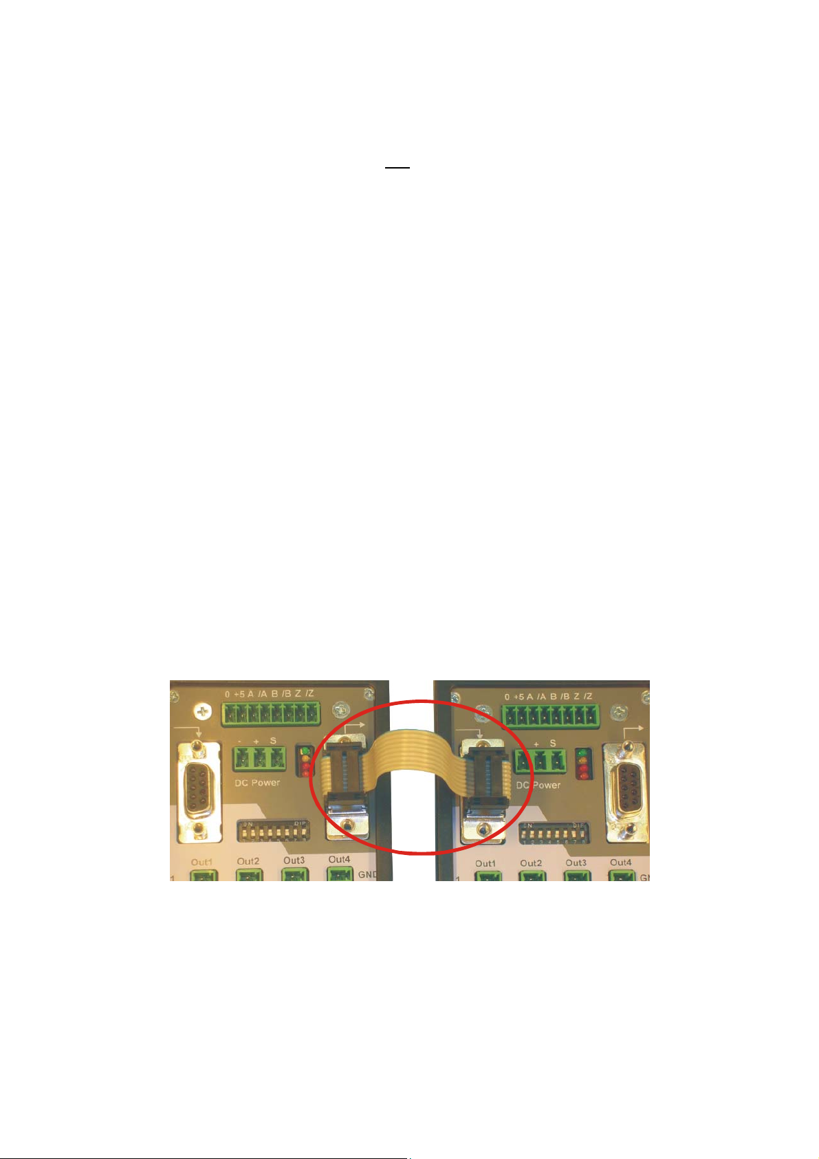
2.5. Cascading of Several Units and Encoder Select Function
The unit can be cascaded very easily to any number of output channels, without loss of regular
encoder outputs. For cascading, pins 1, 3, 5 and 7 of the cascading output of the first unit must
be connected to the corresponding pins of the cascading input of the follower unit.
An appropriate ribbon cable connection is available under motrona part # FK470
FK470