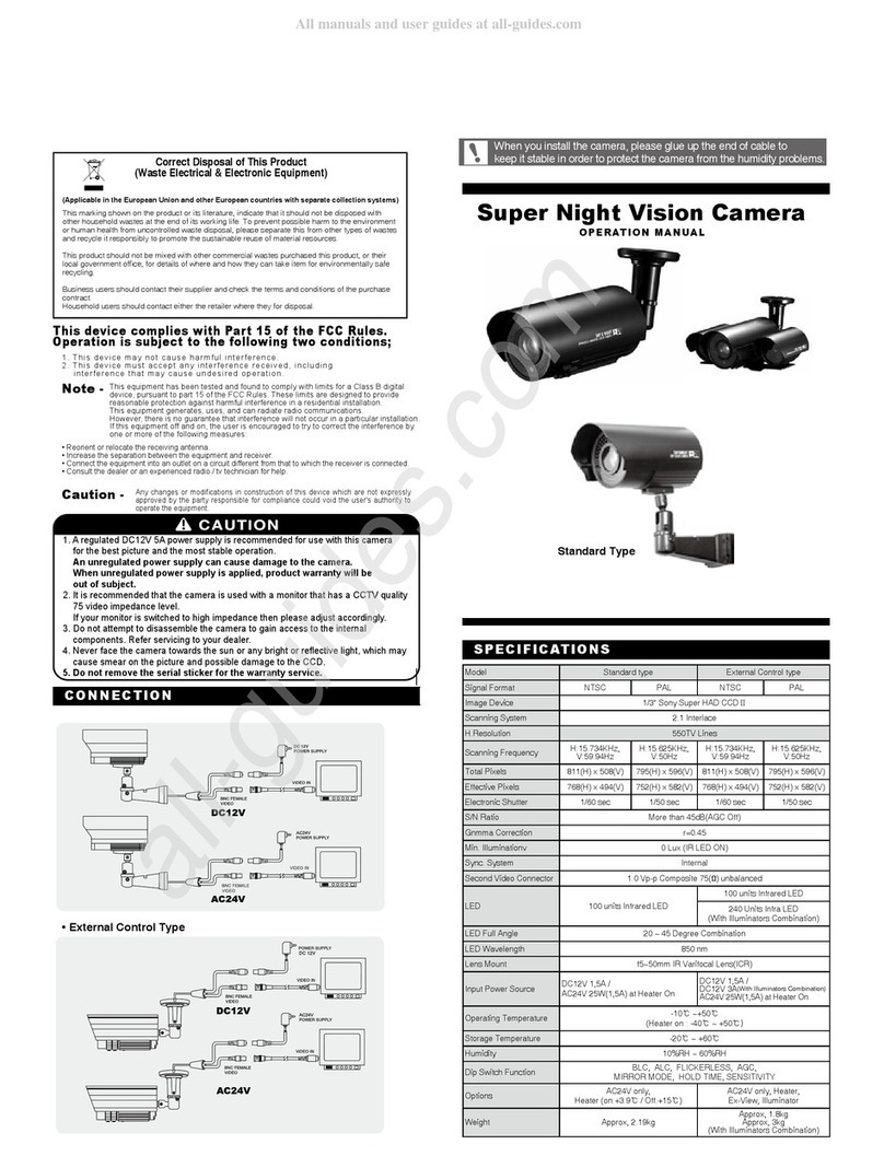
Genesis CCTV BC-540DNI User manual

Product Manual
BC-540DNI

Box Camera :
Color Day/Night w/ICR
Vision with Integrity
www.genesiscctv.com

2
Thank you for purchasing HQ Day&Night Camera. Before using the camera, please read this operation
manual carefully to obtain the best result and keep this manual for future reference.
Table of Contents
FEATURES ······························································· 3
NAME & FUNCTION ················································ 4
Lens Connector ······················································· 8
REAR VIEW & FUNCTION ······································· 6
Setup Switch ···························································· 9
LENS INSTALLATION ··········································· 13
Mounting a Lens ···················································· 14
Back-Focus Adjustment ······································· 15
CAMERA INSTALLATION ······································16
Installation & Tripod Mounting Base
SPECIFICATION ····················································· 17
SUPPLIED ACCESSORIES····································· 18

3
FEATURES
• Day & Night
The Optical Low Pass Filter is switched
automatically and converts the image to color or
monochrome according to the light conditions.
• High sensitivity
Built in interline tranfer method 1/3” Sony Super
HAD CCD, approx 410,000 picture elements.
High Sensitivity, minimum illumination is
0.05Lux (Color Mode), 0.03Lux (B/W Mode) at
F1.2
• High quality image
High resolution, high sensitivity design for a
horizontal resolution of 540 TV lines.
High quality image is obtained by digital signal
processing with optimization of control program
and image correction algorithm.
• Back light compensation
When a camera scene has a strong light source
that shines toward the camera objects in the
foreground will appear as silhouettes. The
backlight compensation function suppresses
the bright back light and exposes detail on
objects that are in the foreground.
• Iris function
The CCD iris function automatically sets the
brightness of the picture by changing the
shutter speed of the camera according to the
incident light levels. This allows a manual iris
lens to be fitted to the camera for internal
applications.

4
NAME & FUNCTION
(Front Panel)

5
1. Lens mount
Mount for lens installation. C-mount lens can be used when C-mount adapter is attached and CS-
mount lens can be used when it is removed.
2. Lens connector
When using an auto iris lens, connect the lens cable to this connector. See page 10.
3. Back-Focus screw
Loosen this screw to adjust “coarse focus”, when correctly adjusted tighten the screw. See page 17.
4. Tripod mounting base
Mounting base for camera installation. See page 18.

6
REAR VIEW & FUNCTION

7
1. Video output connector
BNC connector that outputs a composite video signal.
2. DC Iris level
Adjusts the lens iris level when using a DC(direct drive) type auto iris lens.
3. V-Phase adjust
Adjusts the phase when cameras are using the line lock function.
4. Setup switch
Switch for camera setup according to the operating circumstances. See page 11~13.
5. Power input terminal
Connect to 12VDC or 24VAC power source. When operating with 12VDC or 24VAC power supply, use
only an isolated power source. (Be sure not to connect the power source until all other connections are
completed)
6. Lens select switch
When using an auto IRIS lens, set the switch according to the lens type.
VIDEO : Set to this position when using a Video type lens.
DC : Set to this position when using a DC (galvanometric) type lens.
7. Video Voltage Adjust (Option)
Allows the video output of the camera to be increased when driving long cable runs.

8
Lens Connector
When using an auto IRIS lens, connect the lens cable to the lens plug.
•
Video IRIS type lens
:
Set lens switch to VIDEO, and put the lens cable into the lens connector.
If the plug on the cable is a different type, replace it with the provided 4-pin
iris plug.
• DC IRIS type lens :
Set lens switch to DC, and put the lens cable into the lens connector.
If the plug on the cable is a different type, replace it with the provided 4-pin
iris plug.
• Pin Assignment •
VIDEO Iris type Lens
•
DC Iris type Lens
Pin No.
1
2
3
4
Signal
+9V DC (50mA max)
NC
Video
GND
Pin No.
1
2
3
4
Signal
Damping coil(-)
Damping coil(+)
Drive coil(+)
Drive coil(-)
Note :
When using the Auto iris lenes, set-up switch to A.I position on the rear panel.
Auto iris lens can not be operated properly if the switch is set for E.E.

9
Setup Switch
1. AGC (Automatic Gain Control)
At the AGC on setting, camera’s sensitivity is automatically increased when the
level of ambient light drops. AGC function automatically controls signal gain in
the range of maximum 34dB.
2. E.E/A.I (Electronic Shutter Control)
When using a fixed IRIS lens, the brightness of the picture image will be fixed by
setting E.E mode as the shutter speed is automatically varied in the range of 1/60
to 1/100,000 sec according to the incident light.
Set A.I mode when VIDEO type or DC type auto IRIS lens is used.

10
3. BLC (Back Light Compensation)
Strong light, such as a spotlight, entering the scene back ground causes the lens
iris to close, thereby possibly obscuring desired portions of the scene.
Backlight compensation function automatically adjust the light level
compensation, so that user can always obtain a clear picture, the finest detail
and perfect light contrast.
The camera has 5 BLC zones in it’s field of view. During BLC operation the BLC sensing
zone uses the two upper zones as shown on the diagram on the left. When BLC is applied
video levels are adjusted so that objects can be distinguished more clearly in
unfavourable light conditions.
4. FLK (Flickerless)
If the camera is used with 50Hz fluorescent lighting, there will be flicker on the
screen. In this case, set the FLK on. But FLK should be OFF in 60Hz power
source.
Flickerless mode can overcome flickering on the screen in case that the AC
power frequency is different from the vertical sync frequency of the camera.
0
243
1

11
5. ATW (Auto-Tracking White Balance)
At the ATW on setting, color temperature is automatically adjusted and true color
image can be shown.
PUSH : White balance is fixed under the present light temperture.
6. Video Voltage Adjustment(Optional)
The longer cable installed, the lower Ω(ohm) rate applied.
75Ω : Default 51Ω 30Ω 10Ω

12
• L.L/INT(Line-Lock/Internal)
Line lock or internal sync mode are automatically selected by the type of power supply used to power
the camera.
When using the camera in line lock mode(with an AC supply) it is possible to adjust the V phase
alignment between 0 and 270 degrees.
Note :
At the L.L setting, the camera’s vertical synchronization is driven by the AC signal supplied by AC
PSU.
• When in line lock mode the camera synchronization may not be correct for a few seconds after
power up. This is normal.
• If horizontal lines rolling upward or downward observed from the screen, reverse the polarity of
the power cable connected to the power input connector.

13
LENS INSTALLATION
• Please connect a lens cable when DC type lens or Video
type lens is applied.
• E.E/A.I switch on the rear panel should be set to
E.E position when manual IRIS lens is used.
• When using a Video type lens please adjust the iris level
using the lenses onboard adjusters.
• When using a DC type lens please adjust the iris level by
using the lens level adjuster on the camera’s rear panel.

14
• Mounting a lens
Remove the lens mount cap from the camera
Attach or remove the C-mount adapter depending on the lens to be used.
- If the adapter is attached so tightly that is difficult to remove, use long - nosed
pliers to remove it.
Insert the tips of the pliers into the holes with no threads, thus turn to remove.
A screwdriver can be also used. Insert M2.6 Screws into the holes so that the screw driver has
something to grip.(Store the C-mount adapter for possible future use)
Attach the lens to the mount and secure it so that it does not become loose.
If the lens has an auto-IRIS mechanism, connect the lens connector.
- When a Video-IRIS lens is used, lens switch should be set VIDEO position.
- When a DC IRIS lens is used,lens switch should be set DC position.
• ADJUSTING AUTO-IRIS LENSES
Make this adjustment after connecting the camera to a power source and a monitor.
Set AGC mode to “Off”.
When using a Video type lens. Adjust the iris level on the lens to produce minimum smear and optimum
picture quality.
When using a DC type lens. Use the cameras onboard DC iris level adjuster to produce minimum
smear and optimum picture quality.
Set AGC mode to “On”. It is recommended to set AGC mode on after adjusting the video level.

15
• Back-Focus Adjustment
- When a lens is mounted, Back-Focus Adjustment can be
required. Adjust with the lens focus ring when the correct
focus cannot be obtained.
• With a Fixed-Focus Lens
- Fully open the aperture and set the focus ring to
“∞”(infinity). In the case of an auto IRIS lens only, shoot a
comparatively dark object so that the aperture is fully open.
- Loosen the back-focus screw with a L-wrench, and turn the lens mount to focus.
- After adjusting the back-focus, tighten the back-focus screw.
• With a Vari-focal Lens
- Fully open the aperture and set the lens to the maximum tele-photo position. Then turn the focus ring
to focus. In case of an auto IRIS lens only, shoot a comparatively dark object so that aperture is fully
open.
- Set the lens to its maximum wide-angle position.
- Loosen the back-focus screw with a L-wrench, and turn the lens mount to focus. After adjusting the
back-focus, tighten the back-focus screw.
- Repeat above step until the difference between focusing position “Tele” and “Wide” becomes the
smallest.

16
CAMERA INSTALLATION
• Installation
Camera can be installed on a tripod or a fixing part from
the upper or the bottom plate by using the camera fixing
holes (1/4, 20UNC) on the tripod mounting base. The tripod
mounting base is attached on the bottom plate when
shipped from factory.
Move the tripod mounting base when installing the camera
from the upper plate.
There are two camera fixing holes on the tripod mounting
base, Use the two holes to increase the fixing intensity when installing the camera specially.
• Tripod mounting base
1. Remove the tripod
fixing screws to
remove the tripod
mounting base from
the camera bottom
plate.
(Bottom view)
2. Attach the tripod
mounting base on
the upper plate of
the camera with the
tripod fixing screws.
(Side view)

17
SPECIFICATION (Day&Night Camera)
True Day/Night
Image Sensor
Signal System
Effective Pixels
Scanning System
Scanning Frequency
Sync.System
Video Output
Video S/N Ratio
Horizontal Resolution
Minimum Illumination
Function Key
Lens Mount
Camera Mount
Power Source
Power Consumption
Operating Temperature
Operating Humidity
External Dimensions
Weight
Day/Night(ICR)
Sony 1/3” Super HAD CCD
NTSC
410K
525Lines 2:1 Interlace
(H)15.734KHz(V)59.94Hz
Internal(12VDC)/L.L(External, 24VAC), Automatic Switching
1Vpp, 75Ω, Composite Video Signal
48dB (AGC Off)
540 TV Lines
0.05Lux (F1.2, Color)
AGC, EE/AI, FLK, BLC, ATW
C/CS Mount
1/4” 20UNC (Top/Bottom)
12VDC / 24VAC Dual Power(Non Polarity)
12VDC 450mA ±10% / 24VAC 8W ±10%
14˚F ~ 122˚F (-10˚C ~ +50˚C)
Within 90%RH
65(W) x 54(H) x 133(D)
300g
BC-540DNI

18
SUPPLIED ACCESSORIES
- Lens connector plug
- Lens mount cap
- L-Wrench
- Operation manual
- Triped Mounting Base
- Triped fixing screw x 4
- C-Mount adapter
• The lens mount cap and CS-mount adapter are attached when supplied.
Note :
Design and specifications are subject to change without notice.

Table of contents
Other Genesis CCTV Security Camera manuals

Genesis CCTV
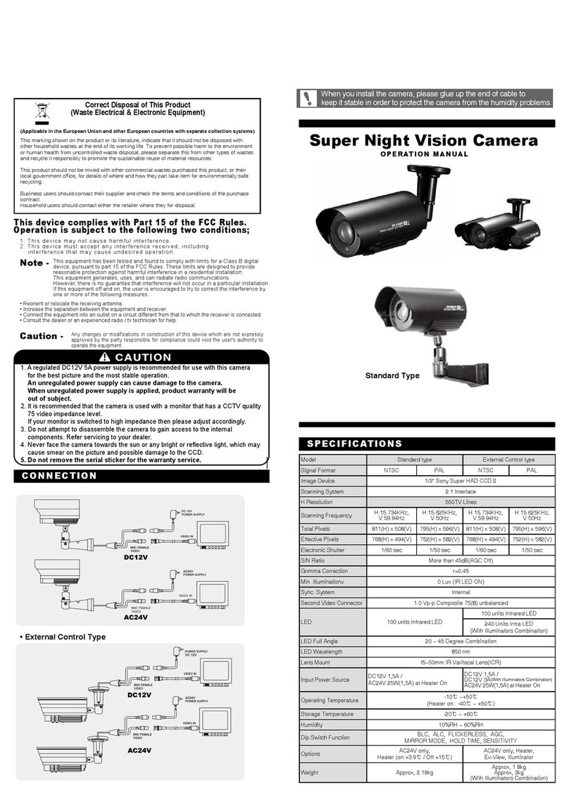
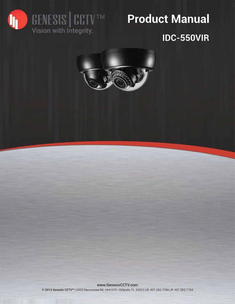
Genesis CCTV IDC-550VIR User manual

Genesis CCTV
Genesis CCTV External Control Type User manual

Genesis CCTV
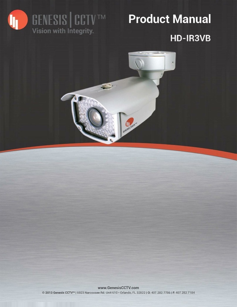
Genesis CCTV HD-IR3VB User manual

Genesis CCTV
Genesis CCTV BC-540WDR User manual

Genesis CCTV
Genesis CCTV VDC-700VIR User manual

Genesis CCTV
Genesis CCTV Standard type User manual

Genesis CCTV
Genesis CCTV IDC-700VIR User manual
Popular Security Camera manuals by other brands

Zhejiang Dahua Vision Technology
Zhejiang Dahua Vision Technology IPC-PFW8840-A180 quick start guide

Sunell
Sunell SN-TPC6406KT-F user manual

NewTek
NewTek 3Play Mini user guide

avertX
avertX HD7012-RW user manual

HIK VISION
HIK VISION DS-7104NI-K1 manual

Grandstream Networks
Grandstream Networks GXV 3615 Series manual