Genesis CCTV BC-540WDR User manual

Box Camera :
Day/Night w/PIXIM’s WDR
Vision with Integrity
www.genesiscctv.com

2
Thank you for purchasing Wide Dynamic Camera. Before using the camera, please read this operation
manual carefully to obtain the best result and keep this manual for future reference.
Table of Contents
FEATURES ······························································· 3
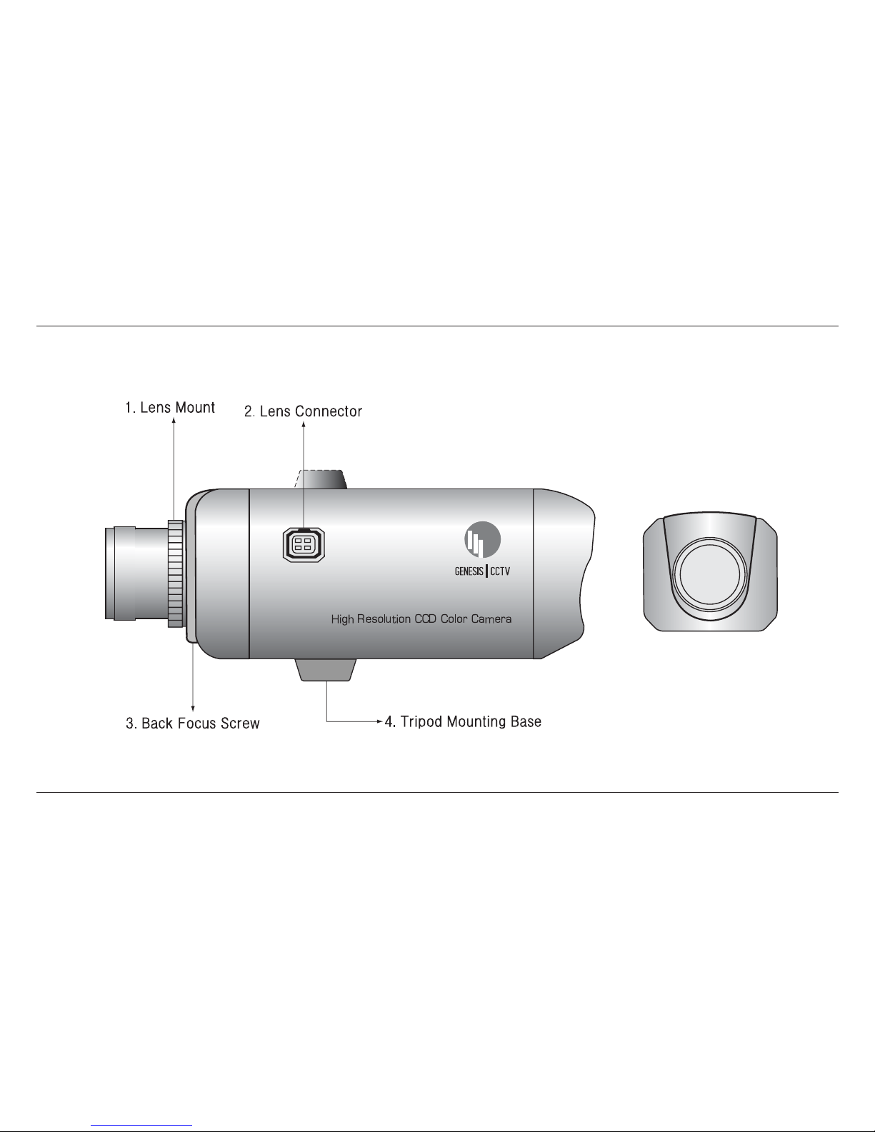
NAME & FUNCTION ················································ 4
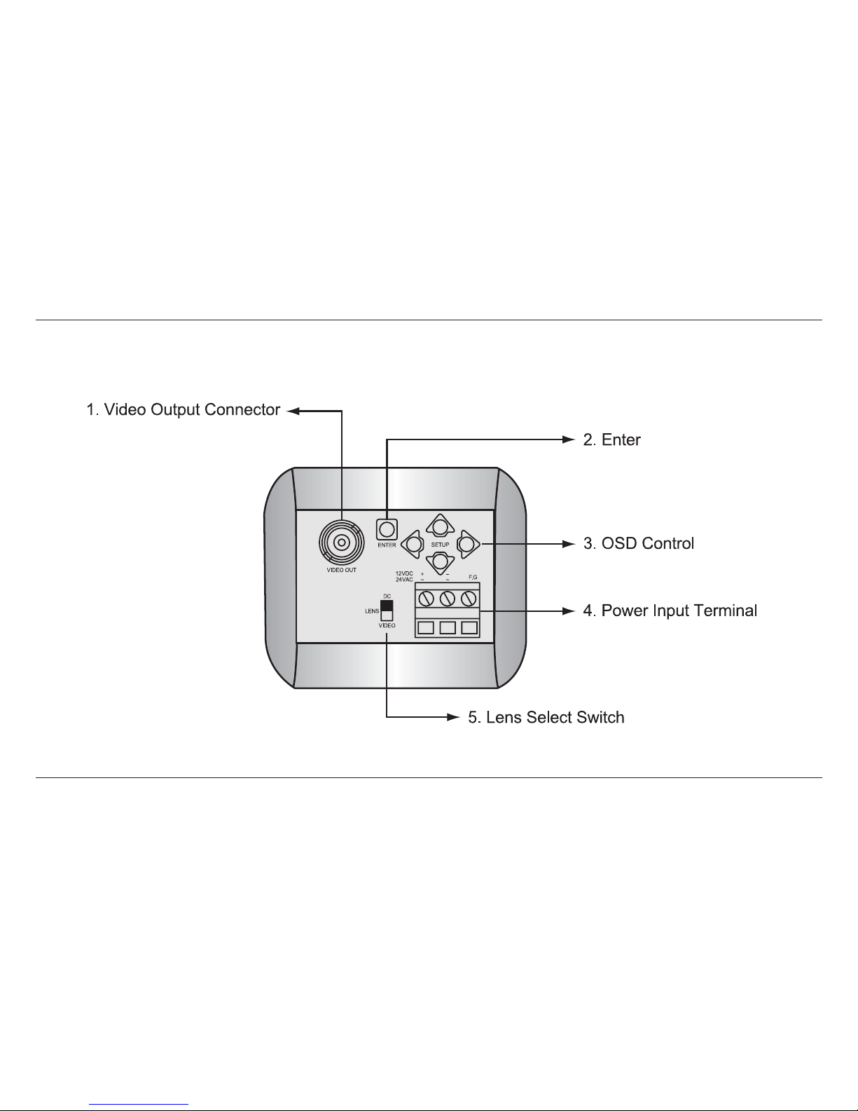
REAR VIEW & FUNCTION ······································· 6
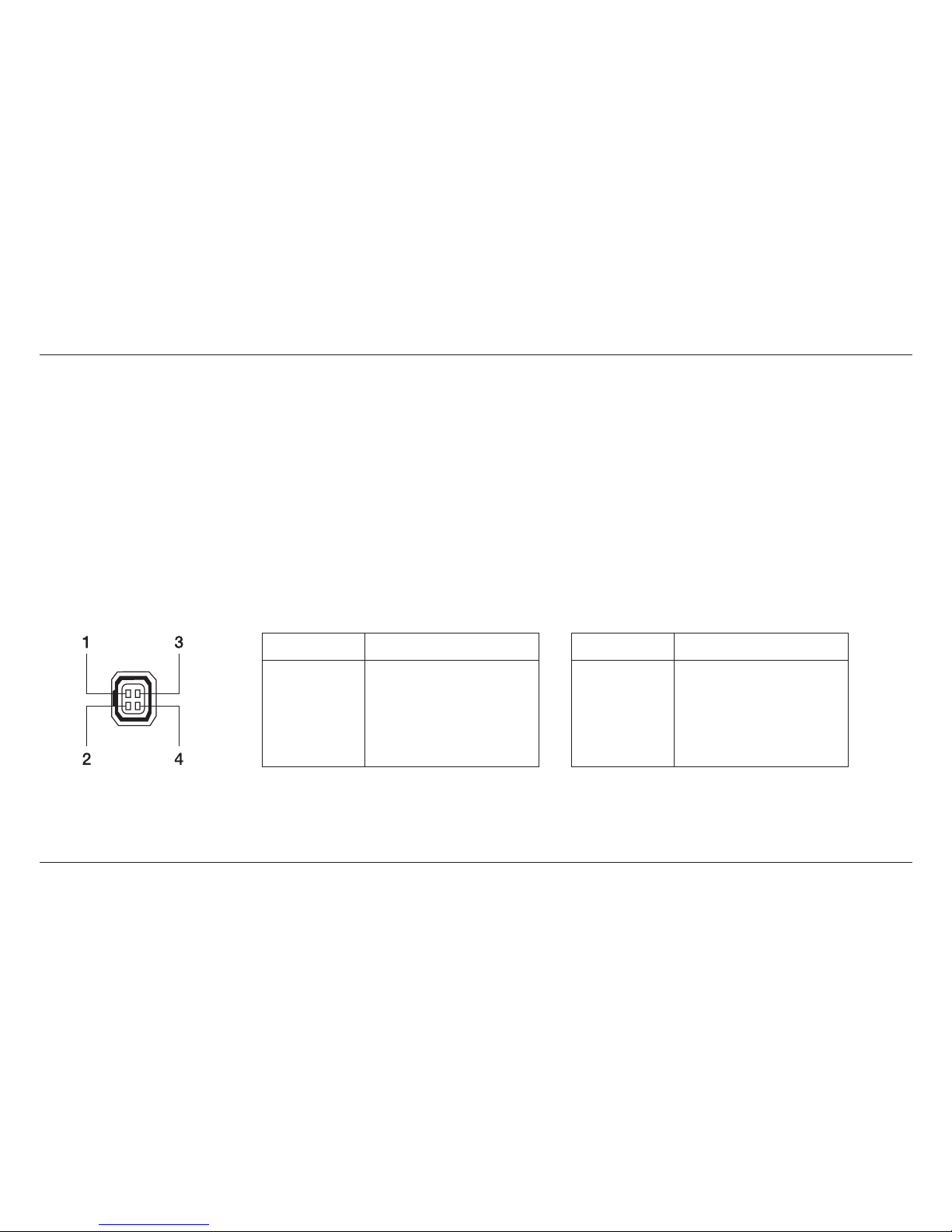
Lens Connector ······················································· 8
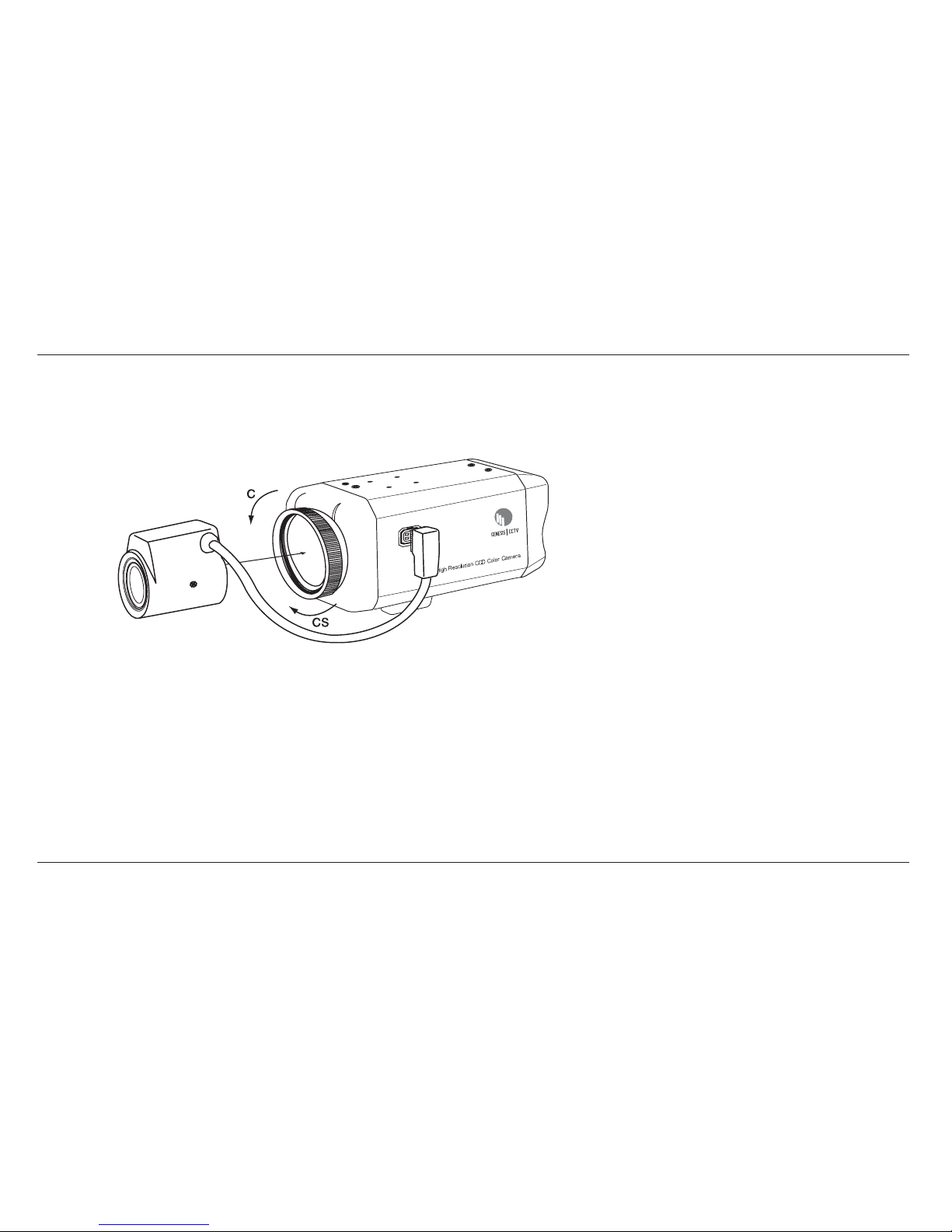
LENS INSTALLATION ··············································9
Mounting a Lens ···················································· 10
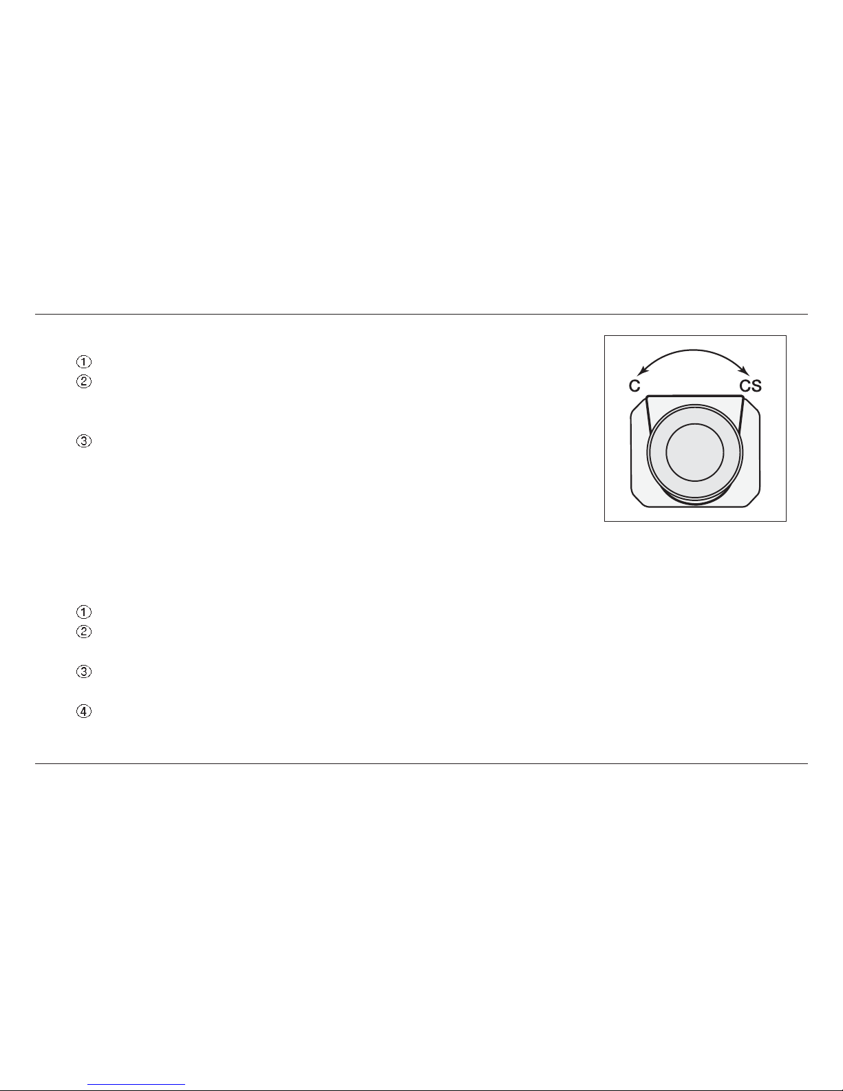
Back-Focus Adjustment ······································· 11
CAMERA INSTALLATION ····································· 12
Installation & Tripod Mounting Base
OSD Manual ·························································· 13
SPECIFICATION ····················································31
SUPPLIED ACCESSORIES···································· 33

3
FEATURES
• Superior Images even in tough back light conditions
• 1/3" Digital Pixel System & Innovative 32 Bit DSP
• Wide Dynamic Range : 95dB(14Bit), 120dB Max.
• More than 540TVL of Horizontal Resolution
• High speed, automatic 5 level exposure control for each pixel
• Multiple camera options, including premium class of WDR using Digital Pixel System
• Wide Range of visible scene in real time
• Good Smearless even in the presense of strong light.
• Catch the image of fast moving object.
• Motion Detection and Digital Pan/Tilt/Zoom
• On Screen Menu and Camera ID
• C/CS Mount Lens Available
• 12VDC/24VAC Dual Power(Non-polarity)

4
NAME & FUNCTION
(Front Panel)

5
1. Lens mount
Mount for lens installation. See page 9.
2. Lens connector
When using an auto iris lens, connect the lens cable to this connector. See page 8.
3. Back-Focus screw
Screw it after adjusting the back-focus to fix the setting. See page 11.
4. Tripod mounting base
Mounting base for camera installation. See page 12.

6
REAR VIEW & FUNCTION

7
1. Video output connector
BNC connector that outputs a composite video signal.
2. Enter
3. OSD control
Push arrow keys to move the cursor to left, right, up and down.
4. Power input terminal
Connect to 12VDC or 24VAC power source. When operating with 12VDC or 24VAC power supply, use
only an isolated power source. (Be sure not to connect the power source until all other connections are
completed)
5. Lens select switch
When using an auto IRIS lens, set the switch according to the lens type.
VIDEO : Set to this position when using a Video type lens.
DC : Set to this position when using a DC (galvanometric) type lens.

8
Lens Connector
When using an auto IRIS lens, connect the lens cable to the lens connector.
•
Video IRIS type lens
:
Set lens switch to VIDEO, and put the lens cable into the lens connector.
If the plug on the cable is a different type, replace it with the provided 4-pin
iris plug.
• DC IRIS type lens :
Set lens switch to DC, and put the lens cable into the lens connector.
If the plug on the cable is a different type, replace it with the provided 4-pin
iris plug.
• Pin Assignment •
VIDEO Iris type Lens
•
DC Iris type Lens
Pin No.
1
2
3
4
Signal
+9V DC (50mA max)
NC
Video
GND
Pin No.
1
2
3
4
Signal
Damping coil(-)
Damping coil(+)
Drive coil(+)
Drive coil(-)

9
LENS INSTALLATION
• Please connect a lens cable when using the DC type
lens or VIDEO type lens.
• When using the VIDEO type lens, please adjust a
brightness of image by volume attached with the lens.

10
1. Mounting a lens
Remove the lens mount cap from the camera
Attach the lens to the mount. Secure it so that it does not become loose
- C Mount lens : Turn the adaptor ring to counterclockwise.
- CS Mount lens : Turn the adaptor ring to clockwise.
If the lens has an auto-IRIS mechanism, connect the lens connector.
- When installing a Video-IRIS lens, lens switch should be set to VIDEO
position.
- When installing a DC IRIS lens, lens switch should be set to DC
position.
2. Adjusting Auto-IRIS Lenses
Make this adjustment after connecting the camera to a power source and a monitor.
Set AGC mode to off.
When using a Video type lens : Adjust the level on the lens to produce minimum smear and optimum
pictures.
When using a DC type lens : Adjust the video level on the rear panel to produce minimum smear and
optimum pictures.
Set AGC mode to on. It is recommended that AGC be used in the “on” mode after adjusting the video level.

11
3. Back-Focus Adjustment
- When a lens is mounted, back-focus adjustment can be
required. Adjust with the lens focus ring when the correct
focus cannot be obtained.
4. With a Fixed-Focus Lens
- Fully open the aperture and set the focus ring to
“∞”(infinity). In the case of an auto IRIS lens only, shoot a
comparatively dark object so that the aperture is fully open.
- Loosen the back-focus screw with a L-wrench, and turn the lens mount to focus.
- After adjusting the back-focus, tighten the back-focus screw.
5. With a Vari-focal Lens
- Fully open the aperture and set the lens to the maximum tele-photo position. Then turn the focus ring
to focus. In case of an auto IRIS lens only, shoot a comparatively dark object so that aperture is fully
open.
- Set the lens to its maximum wide-angle position.
- Loosen the back-focus screw with a L-wrench, and turn the lens mount to focus. After adjusting the
back-focus, tighten the back-focus screw.
- Repeat above step until the difference between focusing position “Tele” and “Wide” becomes the
smallest.

12
CAMERA INSTALLATION
1. Installation
Camera can be installed on a tripod or a fixing part from
the upper or the bottom plate by using the camera fixing
holes (1/4, 20UNC) on the tripod mounting base. The tripod
mounting base is attached on the bottom plate when
shipped from factory.
Move the tripod mounting base when installing the camera
from the upper plate.
There are four tripod fixing screws on the tripod mounting
base, Use four holes to increase the fixing intensity when installing the camera specially.
2. Tripod mounting base
Remove the tripod
fixing screws to
remove the tripod
mounting base from
the camera bottom
plate.
(Bottom view)
Attach the tripod
mounting base on
the upper plate of
the camera with the
tripod fixing screws.
(Side view)

13
OSD Manual
*How to Operate Camera OSD:
Use the five buttons on the rear of this product to configure the features.
• Click the ENTER button. The features will start to be configured. The main menu is displayed on the
monitor.
• Click the Up/Down button to move your selection vertically and to point to the selection.
• Use the Left/Right button to change the current state. By using the Left/Right button, optional values or
states will be displayed in sequence. Click the button until the state you want is displayed.
• Select EXIT on each page and press ENTER button on rear panel for several seconds to end the setting.
These settings cannot be saved.
• To move to a submenu, click the ENTER button in the mode that has a period (.).

14
1. SYSTEM INFORMATION
• CAMERA TYPE: Displays the current TV system.
• H/W VERSION: Displays the hardware version.
• S/W VERSION: Displays the software version.
• FACTORY DEFAULTS RESET: Changes the values to the factory
settings and saves the settings.
• EXIT: Moves to the previous page.
MAIN MENU
SYSTEM INFORMATION
CAMERA SETUP
WDR SETUP
DISPLAY SETUP
EXIT

15
2. CAMERA SETUP
• VIDEO SETUP: Selects TV SYSTEM (NTSC/PAL), SYNC
(INTERNAL/L.L) and SYNC AUTOSENSE(ON/OFF).
• LENS SELECTION: Selects a lens type (DC/VIDEO/MANUAL).
• VIDEO ADJUSTMENT: Sets WHITE BALANCE, AGC, BLC,
FLICKERLESS, GAMMA, RESOLUTION,
SHARPNESS, and SATURATION.
• D&N SETUP: Selects COLOR or BW
• SAVE&EXIT: Saves the changed values of the current page and
moves to the previous page.
• EXIT: Moves to the previous page.
2.1 VIDEO SETUP
CAMERA SETUP » VIDEO SETUP

16
2.1.1 TV SYSTEM
• SETUP LEVEL: Selects between 0 IRE and 7.5 IRE (Minimum black level of camera)
• VIDEO LEVEL: Sets the level of the video display signal.
• COLOR BAR: Displays the color bar on the monitor.
2.1.2 SYNC
• INT: Internal. Internal synchronization method
• L.L: LineLock. Power synchronization method (When an input voltage of 24VAC is used)
Select a V-PHASE value (0-624).
CAMERA SETUP » VIDEO SETUP » TV SYSTEM » NTSC, PAL
CAMERA SETUP » VIDEO SETUP » SYNC » LL

17
2.1.3 SYNC AUTOSENSE
• OFF: Selects between INT and L.L.
• ON: Synchronization is automatically set depending on the input power.
With a 12VDC power supply, INT will be set. With an 24VAC power supply, L.L will be set.
2.2 LENS SELECTION
• LENS SELECT: Selects one item from DC, VIDEO, and
MANUAL LENS.
- When selecting the DC lens or VIDEO lens, the LENS
selection switch on the rear side of this product should also
be selected accordingly.
• DC GAIN: Controls the AUTO IRIS response rate of the DC lens
as brightness changes.
• VIDEO GAIN: Controls the AUTO IRIS response rate of the
VIDEO lens as brightness changes.
- The lower the gain value, the slower the response rate. The
higher the gain value, the faster the response rate.
- If the value is set too high, hunting may occur.
CAMERA SETUP » VIDEO SETUP » SYNC AUTOSENSE
CAMERA SETUP » LENS SELECTION

18
• AI THRESH: Controls the gain value of the system where AUTO IRIS starts operating.
- As the gain value gets lower, IRIS operates in an environment where the light is stronger. As the gain
value gets higher, the IRIS operates in an environment where the light is weaker.
- Disable this menu if MANUAL LENS is selected.
2.3 VIDEO ADJUSTMENT
• WHITE BALANCE
• AGC: AUTOMATIC GAIN CONTROL. Sets the brightness of the
screen at a low light level.
• BLC: BACKLIGHT COMPENSATION. If the light near the subject is
too strong, the subject will be too dark. In this situation, use
this option to get a better video.
• FLICKERLESS: If the power frequency of the NTSC system is 50 Hz,
use this option to disable any potential flickering of
the screen.
• GAMMA: Corrects the gamma of the screen.
• RESOLUTION: Sets the resolution of the screen.
• SHARPNESS: Sets the SHARPNESS/APERTURE value of the screen.
• SATURATION: Sets the SATURATION (CHROMA) value of the
screen.
CAMERA SETUP » VIDEO ADJUSTMENT

19
2.3.1 WHITE BALANCE
• ATW: AUTO TRACKING WHITE BALANCE. Automatically sets the
value of white balance (Range: color temperature of 2,800
to11,000 K).
- ATW SPEED: The higher the value, the slower the tracking rate.
- WB BIAS: Sets the color temperature, which is the reference
point of ATW operation.
• PUSH AWB: This feature allows you to obtain the screen appropriate
for your current lighting environment. Put the mouse point
on ‘Save AWB&All changes’ from the PUSH AWB
CONFIRM page and click the ENTER button to set the
optimal state automatically.
CAMERA SETUP » VIDEO ADJUSTMENT » WHITE BALANCE

20
• MANUAL: There are two types of
ADJ(Adjustment) modes that
allow you to perform settings in
detail manually:
- KELVIN: Changes the color temperature to
get the screen setting you want.
- R/B: Increases or decreases the values of
RED and BLUE to get the screen
setting you want.
2.3.2 AGC(Automatic Gain Control)
• NORMAL: Increases or decreases the gain value from 0 to 26 dB automatically.
• HIGH: Increases or decreases the gain value from 0 to 34 dB automatically.
• CUSTOM: Sets the gain value from 0 to 60 dB manually.
• LOW: Increases or decreases the gain value from 0 to 18 dB automatically.
* The higher the gain value, the brighter the screen but the higher the noise.
CAMERA SETUP » VIDEO ADJUSTMENT » AGC » CUSTOM
Table of contents
Other Genesis CCTV Security Camera manuals

Genesis CCTV
Genesis CCTV IDC-550VIR User manual

Genesis CCTV
Genesis CCTV Standard type User manual

Genesis CCTV
Genesis CCTV HD-IR3VB User manual

Genesis CCTV
Genesis CCTV BC-540DNI User manual

Genesis CCTV
Genesis CCTV IDC-700VIR User manual

Genesis CCTV
Genesis CCTV External Control Type User manual

Genesis CCTV
Genesis CCTV VDC-700VIR User manual