AutoVu SharpX mobile installation
tip.genetec.com | AutoVu Hardware Guide for SharpX Mobile Installation
EN.410.018-XS(6) | Last updated: October 6, 2016 3
Component What you should know
B LPR
Processing
Unit
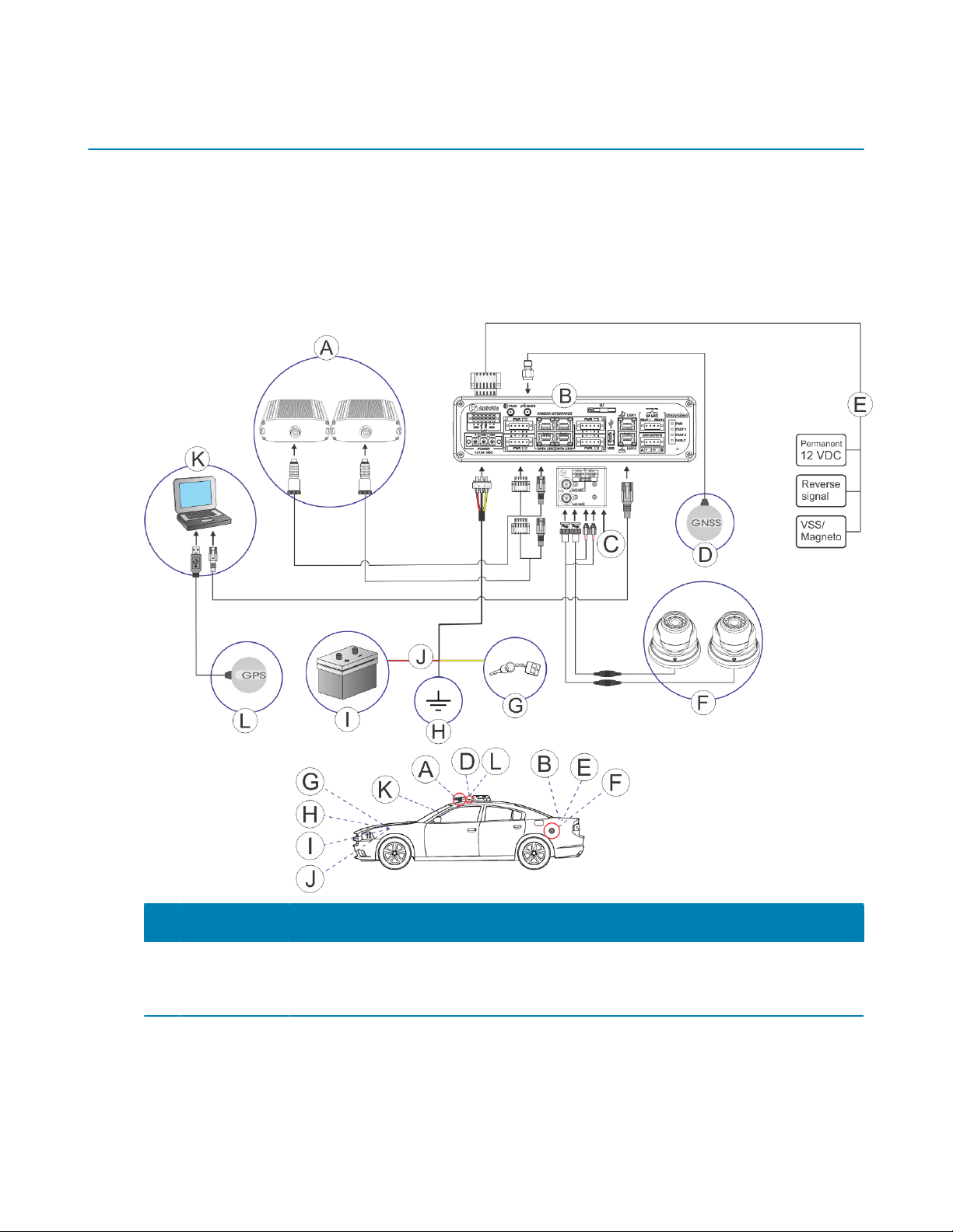
This is the main processing component of the SharpX system. The LPR
Processing Unit is sometimes referred to as the “trunk unit” because it is
typically installed in a vehicle's trunk.This is the main processing component
of the SharpX system. The LPR Processing Unit is sometimes referred to as
the “trunk unit” because it is typically installed in a vehicle's trunk. For more
information, see About mounting the LPR Processing Unit on page 11.
C Tire/Aux
Imaging
Adapter
Module
If the installation includes wheel imaging cameras that require a BNC
connection, you will need to install the Tire/Aux Imaging Adapter Module. For
more information, see Connecting a wheel imaging camera on a SharpX system
on page 48.
D Satellite
navigation
antenna
The GNSS satellite navigation antenna is connected to the LPR Processing Unit
and works in conjunctions with the NAV inputs to provide precise geocoding
for the vehicles associated with the plate reads. For more information on which
satellite navigation hardware to install, see Navigation hardware options on
page 52.
E Navigation
inputs
LPR Processing Unit's NAV inputs can provide odometry readings to Patroller.
The Patroller software uses this information to provide precise geocoding
for the vehicles associated with the plate reads. For more information on the
NAV connections, see Installing the AutoVu Navigation Option on the LPR
Processing Unit on page 61
F Wheel
imaging
cameras
(optional)
Wheel imaging cameras are used for virtual tire-chalking technology that takes
images of the wheels of vehicles to prove whether they have moved between
two license plate reads. For information, see About installing wheel imaging
cameras in a mobile AutoVu system on page 43.
G Vehicle’s
ignition
Yellow wire is connected to vehicle’s ignition. For more information, see
Connecting the LPR Processing Unit to the ignition signal on page 40.
H Ground Black wire is grounded to vehicle’s frame or chassis. For more information, see
Connecting power to the LPR Processing Unit on page 39.
I Vehicle’s
battery
Red wire is connected from the power cable through a 15A ATO/ATC in-line fuse
to vehicle’s battery. For more information, see Connecting power to the LPR
Processing Unit on page 39.
J Power cable
in-line fuse
Red wire is connected to vehicle’s battery. The fuse is installed as close to the
battery as possible. For more information, see Connecting power to the LPR
Processing Unit on page 39.
K Mobile data
computer
(MDC)
For instructions on how to install the in-vehicle MDC mount, refer to your
mount manufacturer’s documentation.
L Satellite
navigation
receiver
The USB GPS satellite navigation receiver is connected to the in-vehicle
computer for systems that do not include the external Navigator box or the LPR
Processing Unit with AutoVu Navigation Option. For more information on which
satellite navigation hardware to install, see Navigation hardware options on
page 52.