Genie Z-135/70 User manual

Operator’s Manual
Z-135/70
Second Edition
First Printing
Part No. 114475
Serial Number Range
after 00000
with
Maintenance
Information
CE

Operator's Manual Second Edition • First Printing
Z-135/70 PartNo.114475
Copyright © 2005 by Genie Industries
First Edition: Third Printing, August 2006
Second Edition: First Printing, February 2007
"Genie" and "Z" are registered trademarks of
Genie Industries in the U.S.A. and many other
countries.
Printed on recycled paper
Printed in U.S.A.
Important
Read,understandandobey thesesafety rulesand
operating instructions before operating this machine.
Only trained and authorized personnel shall be
permitted to operate this machine. This manual
should be considered a permanent part of your
machine and should remain with the machine at all
times. If you have any questions, call Genie Industries.
Contents
Page
Introduction ................................................................ 1
Symbols and Hazard Pictorials Definitions................. 3
GeneralSafety........................................................... 5
PersonalSafety ......................................................... 7
Work Area Safety....................................................... 8
Legend ...................................................................... 16
Controls .................................................................... 17
Inspections ............................................................... 25
OperatingInstructions ............................................... 38
TransportandLifting Instructions .............................. 49
Maintenance ............................................................. 52
Specifications ........................................................... 55
Contact us:
Internet:http://www.genielift.com
e-mail:[email protected]

Operator'sManualSecond Edition · First Printing
PartNo.114475 Z-135/70 1
Introduction
Danger
Failure to obey the instructions and
safety rules in this manual will
result in death or serious injury.
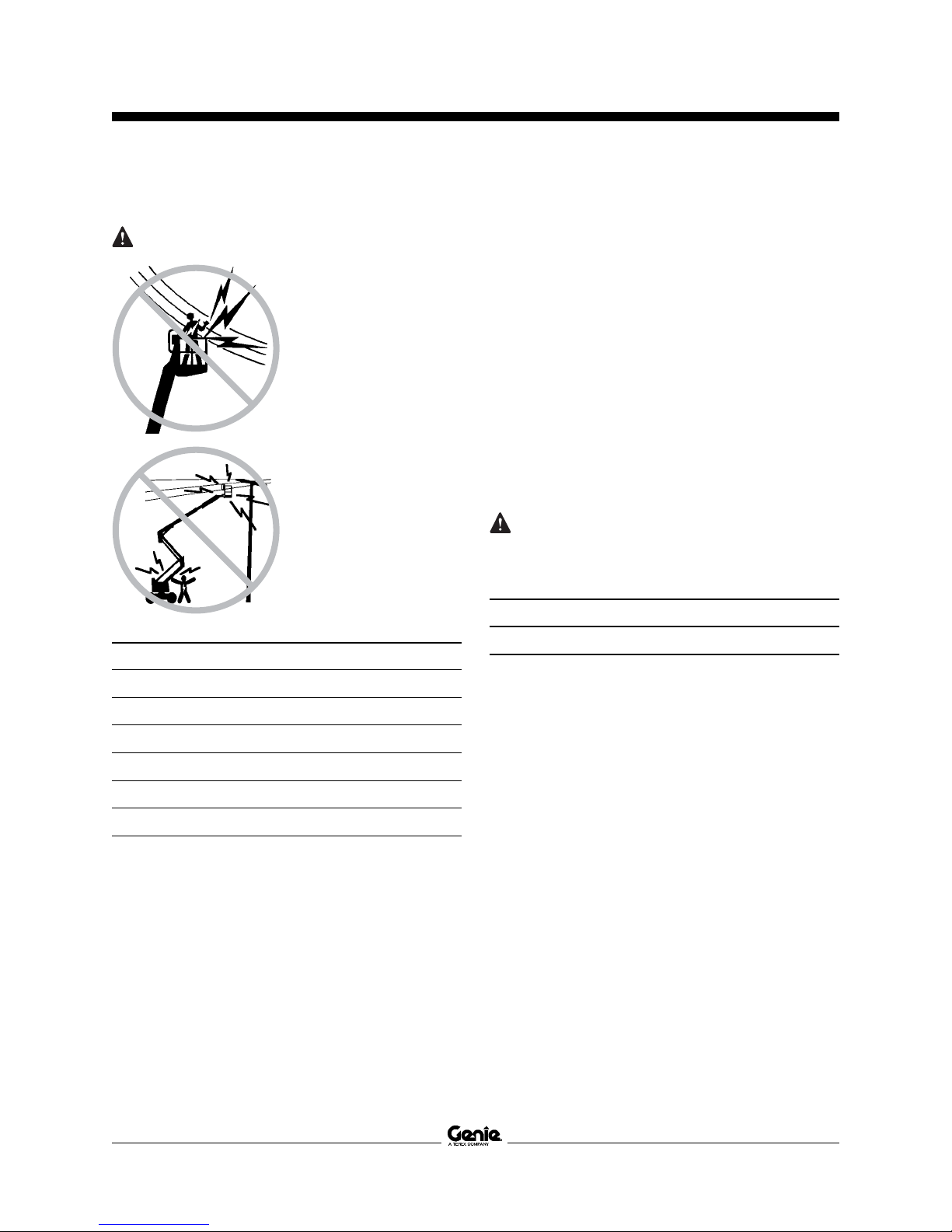
Do Not Operate Unless:
You learn and practice the principles of safe
machineoperationcontainedinthisoperator's
manual.
1 Avoidhazardoussituations.
Knowandunderstandthesafetyrulesbefore
going on to the next section.
2 Alwaysperformapre-operationinspection.
3 Always perform function tests prior to use.
4 Inspect the workplace.
5 Only use the machine as it was intended.
Youread,understand andobeythe
manufacturer'sinstructionsand safetyrules—
safetyandoperator'smanualsandmachine
decals.
Youread,understandandobeyemployer's
safety rules and work site regulations.
Youread,understandandobeyallapplicable
governmentalregulations.
Youare properlytrained tosafely operate the
machine.
Owners, Users and Operators:
Genieappreciates your choiceof our machinefor
yourapplication. Ournumber onepriority is user
safety, which is best achieved by our joint efforts.
We feel that you make a major contribution to
safety if you, as the equipment users and
operators:
1 Comply with employer, job site and
governmentalrules.
2 Read, understand and follow the instructions
in this and other manuals supplied with this
machine.
3 Use goodsafe work practices ina
commonsenseway.
4 Onlyhavetrained/certifiedoperators,directed
byinformedandknowledgeablesupervision,
runningthemachine.
If there is anything in this manual that is not clear
orwhich youbelieve should be added, please
contact us.
Internet:www.genielift.com
E-mail:[email protected]

Operator'sManual Second Edition · First Printing
2 Z-135/70 PartNo.114475
Intended Use
This machine is intended to be used only to lift
personnel, along with their tools and materials to an
aerial work site.
Introduction
Safety Sign Maintenance
Replace any missing or damaged safety signs.
Keep operator safety in mind at all times. Use mild
soap and water to clean safety signs. Do not use
solvent-basedcleanersbecausetheymaydamage
the safety sign material.
Hazard Classification
Genie uses symbols, color coding and signal words
to identify the following:
Safety alert symbol—used to alert
youto potentialpersonal injury
hazards. Obey all safety
messages that follow this symbol
to avoid possible injury or death.
Indicatesa hazardous situation
which, if not avoided, will result in
deathor seriousinjury.
Indicatesa hazardous situation
which, if not avoided, could result
in death or serious injury.
Indicatesa hazardous situation
which, if not avoided, could result
inminorormoderate injury.
Indicatesa hazardous situation
which, if not avoided, could result
inpropertydamage.
Red
Orange
Yellow
Blue

Operator'sManualSecond Edition · First Printing
PartNo.114475 Z-135/70 3
Symbol and Hazard Pictorials Definitions
ExplosionHazard
Electrocution
Hazard FallHazard
CrushHazard
Tip-overHazard
Tip-overHazard
Tip-overHazard Electrocution
Hazard Maintainrequired
clearance.
Readtheoperator’s
manual.
Keep off this
surface.
Keepawayfrom
path of moving
platform.
Nosmoking.
Noflame.
Stopengine.
Do not use ether
orotherhigh
energystarting
aids on machines
equippedwith
glowplugs.
Readservice
manual
Ratedplatform
capacity
Platformuphill:
1 Lowerprimary
2 Retract/lower
secondary
3 Retractprimary
Platformdownhill:
1 Retract primary
2 Retract/lower
secondary
3 Lowerprimary
Recovery procedure if tilt alarm sounds
whileelevated.
Onlytrained
maintenance
personnelshould
access
compartments
CrushHazard Keepawayfrom
movingparts.
ExplosionHazard
Disconnectbattery.

Operator'sManual Second Edition · First Printing
4 Z-135/70 PartNo.114475
Symbol and Hazard Pictorials Definitions
Lanyard
attachmentpoint Wheelload Voltageratingfor
powertoplatform Pressureratingfor
air line to platform
Avoid contact. Tie-down
instructions Tie-down
instructions
Fireextinguisher
Weightofwelder
reducescapacity Windspeed
No step. Donotjump-start
this battery.
FireHazard
Tirespecification

Operator'sManualSecond Edition · First Printing
PartNo.114475 Z-135/70 5
General Safety
Safety signs and locations
133179 A
82546 B
272 kg
+
< =
272 kg

Operator'sManual Second Edition · First Printing
6 Z-135/70 PartNo.114475
General Safety
Safety signs and locations
133179 A
133180 A

Operator'sManualSecond Edition · First Printing
PartNo.114475 Z-135/70 7
Personal Safety
Fall Protection
Personal fall protection equipment (PFPE) is
requiredwhenoperatingthismachine.
Occupants must wear a safety belt or harness in
accordancewithgovernmentalregulations.Attach
the lanyard to the anchor provided in the platform.
Operators must comply with employer, job site and
governmentalrulesregardingtheuseofpersonal
protectiveequipment.
All PFPE must comply with applicable
governmentalregulations,andmustbeinspected
and used in accordance with the PFPE
manufacturer’sinstructions.

Operator'sManual Second Edition · First Printing
8 Z-135/70 PartNo.114475
Work Area Safety
Electrocution Hazards
This machine is not
electricallyinsulated
andwill not provide
protection from contact
with or proximity to
electricalcurrent.
Maintain safe distances
fromelectricalpower
linesandapparatusin
accordancewith
applicable
governmental
regulationsandthe
followingchart.
LineVoltage Required Clearance
0 to 50KV 3.0 m
50 to 200KV 4.6 m
200 to 350KV 6.1 m
350 to 500KV 7.6 m
500 to 750KV 10.6 m
750 to 1000KV 13.7 m
Allow for platform movement, electrical line sway or
sag and beware of strong or gusty winds.
Keep away from the machine if it contacts
energizedpowerlines.Personnelonthegroundor
in the platform must not touch or operate the
machine until energized power lines are shut off.
Do not use the machine as a ground for welding.
Donotoperatethemachineduringlightningor
storms.
Beforeperforming service onthis machine,
disconnectthebatteriesunderbothturntable
covers.
Tip-over Hazards
Occupants,equipment and materialsshall not
exceed the maximum platform capacity.
Maximum platform capacity 272 kg
Maximum occupants 2
The weight of options and accessories, such as
pipecradles,panel cradlesandwelders,will reduce
the rated platform capacity and must be factored
into the total platform load. See the decals with the
options.
If using accessories, read, understand and obey
the decals and instructions with the accessory.

Operator'sManualSecond Edition · First Printing
PartNo.114475 Z-135/70 9
Do not raise or extend
the boom unless the
machine is on a firm,
level surface.
Donotdepend onthe
tilt alarm as a level
indicator. The tilt alarm
sounds in the platform
onlywhenthemachine
is on a severe slope.
If the tilt alarm sounds
while the boom is
lowered:Donotextend,
rotateor raise the boom
abovehorizontal.Move
the machine to a firm,
levelsurfacebefore
raisingtheplatform.
If the tilt alarm sounds when the platform is raised:
Use extreme caution. Identify the condition of the
boom on the slope as shown below. Follow the
steps to lower the boom before moving to a firm,
level surface. Do not rotate the boom while
lowering.
If the tilt alarm sounds with the platform uphill:
1 Lowertheprimaryboom.
2 Retract/lowerthesecondary
boom.
3 Retracttheprimaryboom.
If the tilt alarm sounds with the
platformdownhill:
1 Retracttheprimary
boom.
2 Retract/lowerthe
secondaryboom.
3 Lowertheprimary
boom.
Do not raise the boom
whenwindspeedsmay
exceed 12.5 m/s. If
windspeedsexceed
12.5 m/s when the
boomis raised,lower
the boom and do not
continuetooperatethe
machine.
Do not operate the machine in strong or gusty
winds. Do not increase the surface area of the
platform or the load. Increasing the area exposed to
the wind will decrease machine stability.
Useextremecare and
slowspeedswhile
driving the machine in
thestowedposition
acrossuneventerrain,
debris,unstableor
slipperysurfaces and
nearholesanddrop-
offs.
Donot drivethe machine on or nearuneven terrain,
unstablesurfacesorotherhazardousconditions
withthe boomraised orextended.
Work Area Safety

Operator'sManual Second Edition · First Printing
10 Z-135/70 PartNo.114475
Work Area Safety
Do not use air-filled tires. These machines are
equippedwith foam-filledtires.Wheel weightis
critical to stability.
Do not modify or alter an aerial work platform
withoutpriorwrittenpermission from the
manufacturer.Mountingattachmentsforholding
toolsor other materialsonto the platform,toeboards
or guard rail system can increase the weight in the
platform and the surface area of the platform or the
load.
Do not place or attach
overhangingloadsto
any part of this
machine.
Donot placeladders or
scaffolds in the
platformor against any
part of this machine.
Do not transport tools
andmaterialsunless
they are evenly
distributedandcan be
safely handled by
person(s)inthe
platform.
Do not use the machine
on a moving or mobile
surface or vehicle.
Be sure all tires are in good condition and lug nuts
areproperlytightened.
Do not use the machine as a crane.
Do not push the machine or other objects with the
boom.
Do not contact adjacent structures with the boom.
Do not tie the boom or platform to adjacent
structures.
Do not place loads outside the platform perimeter.
Do not push off or pull
towardanyobject outside
of the platform.
Maximum allowable
manual force - CE
400 N
Do not alter or disable machine components that in
any way affect safety and stability.
Do not replace items critical to machine stability
with items of different weight or specification.
Do not replace factory-installed tires with tires of
different specification or ply rating.
Do not use the platform controls to free a platform
thatiscaught, snaggedorotherwise prevented
from normal motion by an adjacent structure. All
personnelmust beremoved from theplatform
before attempting to free the platform using the
groundcontrols.

Operator'sManualSecond Edition · First Printing
PartNo.114475 Z-135/70 11
Fall Hazards
Occupants must wear a
safety belt or harness
inaccordancewith
governmental
regulations. Attach the
lanyardtotheanchor
providedinthe
platform.
Do not sit, stand or
climb on the platform
guardrails.Maintain a
firm footing on the
platform floor at all
times.
Do not climb down from
theplatformwhen
raised.
Keepthe platformfloor
clear of debris.
Lowertheplatform
entry mid-rail or close
theentrygate before
operating.
Do not enter or exit the platform unless the
machine is in the stowed position and the platform
is at ground level.
Operation on Slopes Hazards
Do not drive the machine on a slope that exceeds
the maximum uphill, downhill or side slope rating of
the machine. Slope rating applies only to machines
in the stowed position.
Maximum slope rating, stowed position
Platform downhill 45% (24°)
Platform uphill 30% (17°)
Side slope 25% (14°)
Note: Slope rating is subject to ground conditions
and adequate traction. See Driving on a Slope in
the Operating Instructions Section.
Work Area Safety

Operator'sManual Second Edition · First Printing
12 Z-135/70 PartNo.114475
Collision Hazards
Be aware of limited sight distance and blind spots
whendrivingoroperating.
Beaware of theboom positionand tailswing when
rotatingtheturntable.
Beawareofmachinelengthwhenoperating.The
machine is 12.9 m long.
Checkthe work areafor
overheadobstructions
orotherpossible
hazards.
Beawareof crushing
hazardswhengrasping
theplatformguardrail.
Operatorsmust comply
with employer, job site
andgovernmentalrules
regardingtheuse of
personalprotective
equipment.
Observeand usethe
color-codeddirection
arrowsontheplatform
controlsanddrive
chassis for drive and
steer functions.
Do not operate a boom in the path of any crane
unless the controls of the crane have been locked
outand/or precautionshavebeen takento prevent
any potential collision.
No stunt driving or
horseplaywhile
operatingamachine.
Donotlower theboom
unlesstheareabelow
is clear of personnel
andobstructions.
Limit travel speed
accordingto the
conditionoftheground
surface,congestion,
slope, location of
personnel,andany
otherfactors which
may cause collision.
Bodily Injury Hazard
Do not operate the machine with a hydraulic oil or
air leak. An air leak or hydraulic leak can penetrate
and/orburnskin.
Alwaysoperate themachine ina well-ventilated
areatoavoidcarbonmonoxidepoisoning.
Impropercontactwith componentsunderany cover
will cause serious injury. Only trained maintenance
personnel should access compartments. Access
by the operator is only advised when performing a
pre-operationinspection.Allcompartmentsmust
remainclosedandsecuredduringoperation.
Work Area Safety

Operator'sManualSecond Edition · First Printing
PartNo.114475 Z-135/70 13
Work Area Safety
Explosion and Fire Hazards
Do not start the engine if you smell or detect liquid
petroleumgas (LPG),gasoline, diesel fuelor other
explosive substances.
Donot refuelthe machine withthe enginerunning.
Refuel the machine and charge the battery only in
anopen,well-ventilated areaawayfromsparks,
flames and lighted tobacco.
Donot operatethe machinein hazardous locations
orlocationswherepotentiallyflammableor
explosive gases or particles may be present.
Donotspray etherintoengines equippedwithglow
plugs.
Damaged Machine Hazards
Donot usea damaged ormalfunctioning machine.
Conductathoroughpre-operationinspectionofthe
machine and test all functions before each work
shift. Immediately tag and remove from service a
damagedormalfunctioningmachine.
Besure allmaintenance hasbeen performed as
specifiedin this manualand theappropriateGenie
servicemanual.
Be sure all decals are in place and legible.
Be sure the operator’s, safety and responsibilities
manualsare complete, legible and inthe storage
containerlocated onthe platform.
Component Damage Hazards
Do not use any battery or charger greater than 12V
to jump-start the engine. Apply jumper cables to the
starter and controls battery, not the auxiliary power
batteries.
Do not use the machine as a ground for welding
unless the machine is equipped with the weld line
to platform option and it is properly connected.
Battery Safety
Burn Hazards
Batteries contain acid.
Alwayswearprotective
clothingandeyewear
whenworkingwith
batteries.
Avoid spilling or
contacting battery acid.
Neutralizebatteryacid
spills with baking soda
andwater.
Explosion Hazard
Keep sparks, flames
andlightedtobacco
awayfrombatteries.
Batteries emit
explosive gas.
Electrocution Hazard
Avoid contact with electrical terminals.

Operator'sManual Second Edition · First Printing
14 Z-135/70 PartNo.114475
Pipe Cradle Safety
Read,understandandobeyallwarningsand
instructions provided with the pipe cradles.
Do not exceed the rated platform capacity. The
pipe cradle assembly and the weight in the pipe
cradles will reduce rated platform capacity and
must be factored into total platform load.
The pipe cradle assembly weighs 9.5 kg.
The maximum capacity of the pipe cradle assembly
is 91 kg.
The weight of the pipe cradle assembly and the
load in the pipe cradles may limit the maximum
number of occupants in platform.
Center the load within the perimeter of the platform.
Secure the load to the platform.
Do not obstruct the entrance or the exit of the
platform.
Do not obstruct the ability to operate the platform
controls or the red Emergency Stop button.
Donotoperateunless youareadequately
instructed and are aware of all of the hazards
associated with movement of the platform with an
overhangingload.
Do not cause a horizontal force or side load to the
machine by raising or lowering a fixed or
overhangingload.
ElectrocutionHazard: Keep pipes awayfromall
energizedelectricalconductors.
Panel Cradle Safety
Read,understandandobeyallwarningsand
instructionsprovided with thepanel cradles.
Do not exceed the rated platform capacity. The
combined weight of the cradles, panels, occupants,
tools and any other equipment must not exceed
rated capacity.
The panel cradle assembly weighs 13.6 kg.
The maximum capacity of the panel cradles is
113 kg.
The weight of the panel cradles and the load in the
panel cradles may limit the maximum number of
occupants in platform to one person.
Secure the cradles to the platform. Secure the
panel(s) to the platform railing using the straps
provided.
Donotoperateunless youareadequately
instructed and are aware of all hazards associated
with lifting panels.
Do not cause a horizontal force or side load to
machine by raising or lowering a fixed or
overhangingload.
Maximum vertical height of panels: 1.2 m
Maximum wind speed: 6.7 m/sec
Maximum panel area: 3 m2
Work Area Safety

Operator'sManualSecond Edition · First Printing
PartNo.114475 Z-135/70 15
Work Area Safety
Lockout After Each Use
1 Select a safe parking location—firm level
surface, clear of obstruction and traffic.
2 Retract and lower the boom to the stowed
position.
3 Rotate the turntable so that the boom is between
thenon-steerwheels.
4 Turn the key switch to the off position and
remove the key to secure from unauthorized
use.
5 Chockthe wheels.
Welder Safety
Read,understandandobeyallwarningsand
instructionsprovidedwiththewelding powerunit.
Do not connect weld leads or cables unless the
welding power unit is turned off at the platform
controls.
Donot operateunless theweld cables areproperly
connectedandthewelderisproperlygrounded.
Theweight of thewelder will reduce the rated
platform capacity and must be factored into the
totalplatformload.The welder powersupplyweighs
34 kg.
Donot operatethe welderunless a fire extinguisher
is immediately available for instant use, per OSHA
regulation1926.352(d).
Weld Line to Platform Safety
Read,understandandobeyallwarningsand
instructionsprovidedwiththewelding powerunit.
Do not connect weld leads or cables unless the
welding power unit is turned off at the platform
controls.
Donot operateunless theweld cables areproperly
connected.
Connect the positive lead to the twist-lock
connectorat theturntable andplatform.
Clamp the negative lead to the ground post at the
turntableandplatform.

Operator'sManual Second Edition · First Printing
16 Z-135/70 PartNo.114475
Legend
1 Square-endtire
2 Groundcontrols
3 Secondaryboom
4 Primaryboom
5 Jibboom
6 Platform
7 Platformcontrols
8 Slidingmid-rail
9 Manualstoragecontainer
10 Lanyardanchoragepoint
11 Foot switch

Operator'sManualSecond Edition · First Printing
PartNo.114475 Z-135/70 17
Controls
GroundControl Panel
1 Primaryboomdownbutton
2 Primaryboomextend/retract
buttons
3 Primaryboomupbutton
4 Notused
5 LCDscreencontrolbuttons
6 LCDreadoutscreen
7 RedEmergencyStopbutton
8 Glowplugbutton
9 Key switch for off/ground/
platformselection
10 Enginestart button
11 Enginespeed select button
12 Auxiliarypowerbutton
13 Highspeedfunctionenable
button
14 Lowspeedfunctionenable
button
15 20A circuit breaker for
system circuit
16 Alarm
17 Platformlevelup/down
buttons
18 Jibboomextend/retract
buttons
19 Jibboomup/downbuttons
20 Secondaryboomup/extend
anddown/retractbuttons
21 Platform rotate left/right
buttons
22 Turntablerotateleft/right
buttons

Operator'sManual Second Edition · First Printing
18 Z-135/70 PartNo.114475
Controls
GroundControl Panel
1 Primaryboomdownbutton
Pushtheprimary boomdownbutton
andtheprimary boomwilllower.
2 Primaryboomextend/retractbuttons
Pushthe primary
boomextendbutton
andtheprimary
boomwill extend.
Pushthe primary
boomretractbutton
and the primary boom will retract.
3 Primaryboomupbutton
Push the primary boom up button
and the primary boom will raise.
4 Notused
5 LCDscreencontrolbuttons
6 LCDreadoutscreen
a lowfuelindicator
b engineoilpressureindicator
c watertemperatureindicator
d auxiliarypowerindicator
e highenginerpmindicator
f hourmeter
7 RedEmergencyStopbutton
Push in red Emergency Stop button to the off
position to stop all functions and turn the engine
off. Pull out the red Emergency Stop button to
the on position to operate the machine.
8 Glowplugbutton
Push the glow plug button and hold for 3 to 5
seconds.
9 Key switch for off/ground/platform selection
Turn the key switch to the off position and the
machine will be off. Turn the key switch to the
groundpositionandthegroundcontrolswill
operate. Turn the key switch to the platform
position and the platform controls will operate.
10 Enginestart button
Push the engine start button and the engine will
start.
11 Enginespeed select button
Push the engine speed select button to select
theenginespeed.Whenthearrowabovethe
rabbit is lit, the engine is in high idle speed.
When the arrow above the turtle is lit, the engine
is in low idle speed.
12 Auxiliarypowerbutton
Useauxiliary powerif theprimary power source
(engine)fails.
Simultaneouslypushtheauxiliary power button
and activate the desired function.
13 Highspeedfunctionenablebutton
Push the high speed function enable switch to
enablethefunctions ontheground controlpanel
tooperate at highspeed.
14 Lowspeedfunctionenablebutton
Push the low speed function enable switch to
enablethefunctions ontheground control panel
to operate at low speed.
15 20A circuit breaker for system circuit
16 Alarm
ab c de f
Other manuals for Z-135/70
2
Table of contents
Other Genie Boom Lift manuals

Genie
Genie Z-45/25 User manual

Genie
Genie S-65 XC CE Installation and operating manual

Genie
Genie Z-34/22 User manual

Genie
Genie Z-34/22 User manual

Genie
Genie TZ-50 User manual

Genie
Genie Z-45/25 User manual

Genie
Genie S-40 TRAX User manual

Genie
Genie GS-2646 User manual

Genie
Genie S-80 XC User manual

Genie
Genie S-100HD User manual

Genie
Genie S-65 User manual

Genie
Genie S-80 Installation and operating manual

Genie
Genie S-60 HC User manual

Genie
Genie S-100 User manual

Genie
Genie S-60 HC User manual

Genie
Genie gS-1530/32 User manual

Genie
Genie GTH-1048 User manual

Genie
Genie ZX-135/70 with Jib-Extend User manual

Genie
Genie Super-Straddle User manual

Genie
Genie Z45/25J Operating manual