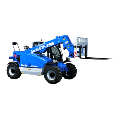
Genie GTH-2306 Service manual

Handler with telescopic boom
GTH-2306
OPERATOR HANDBOOK
Document 57.0002.2200 - 12/2002
CAUTION: THOROUGHLY READ AND UNDERSTAND THIS HANDBOOK BEFORE OPERATING THE MACHINE
CAUTION: KEEP THIS HANDBOOK IN THE MACHINE AT ALL TIMES
English
Edition


Operator Handbook 57.0002.2200 - GTH-2306
All rights reserved. No part of this publication may be reproduced, stored in a retrieval system or transmitted in any form or by
any means without prior written permission from TEREXLIFT srl.
In pursuing a policy of constant quality improvement, TEREXLIFT srl reserves the right to make changes at any time and
without undertaking to give prior notice; therefore, also this publication may be subject to modifications.
Some photos or drawings have been used to illustrate a specific function; as a result, they may not refer to the machine
treated in this manual.
© Copyright 2002 TEREXLIFT srl - All rights reserved
Produced by:
EUROPEAN TECHNICAL SERVICES
GENIE FRANCE
10 Z.A. de la Croix Saint-Mathieu
28320 Gallardon
France
Tel. : 0033 (0)2 37 26 09 99
Fax : 0033 (0)2 37 26 09 98
GENIE GERMANY
Finienweg 3
28832 Achim/Bremen
Germany
Tel. : 0049 (0)4202 8852 0
Fax : 0049 (0)4202 8852 20
GENIE IBÉRICA
Gaià31
Poligono Industrial Plàd’en Coll
08110 Montcada i Reixac
Barcelona
Spain
Tel. : 0034 93 579 5090
Fax : 0034 93 579 5091
GENIE SCANDINAVIA
Tagenevägen 72
425 37 Hisings Kärra
Sweden
Tel. : 0046 315 751 00
Fax : 0046 315 790 20
GENIE UK
The Maltings
Wharf Road
Grantham
Lincs NG31 6BH
United Kingdom
Tel. : 0044 (0)1476 584333
Fax : 0044 (0)1476 58433


Document 57.0002.2200 - 12/2002
Page 1
Handler with telescopic boom
GTH-2306
■
I
NTRODUCTION
This handbook provides information for a safe and
proper operation and maintenance of the machine.
STRICTLY COMPLY WITH THE INSTRUCTIONS
GIVEN IN THIS HANDBOOK!
READ AND UNDERSTAND THIS HANDBOOK
BEFORE STARTING, USING AND CARRYING
OUT ANY OPERATION WITH AND ON THE
MACHINE.
The handbook is divided into seven sections:
Sect. AGENERAL INFORMATION
Sect. BSAFETY
Sect. COPERATING INSTRUCTIONS
Sect. DMAINTENANCE
Sect. ETROUBLESHOOTING
Sect. FOPTIONAL ATTACHMENTS
Sect. GTABLES AND ENCLOSURES
Section Acontains general concepts that are decisive
for the knowledge of the main parts of the machine.
It also contains all necessary data for a correct
identification of the machine, the technical features of
the machine, etc.
Section Bis especially addressed to the personnel,
who shall operate, repair and service the machine, and,
in case of companies with a wide fleet of machines, to
the safety responsible.
It describes the essential compulsory qualities of the
personnel in charge and other important information
for the safety of persons and things.
Section Cis mainly addressed to the operators who
operate the machine. This section illustrates all control
devices.
Additionally, it contains the main use instructions -i.e.
engine starting, machine parking, machine storing.
Section Dis addressed to the maintenance responsible
and the servicemen.
The section describes the maintenance schedule and
the relevant intervals.
Section E deals with the failure diagnostics.
Section Fmakes a list of the main interchangeable
attachments that can be coupled to the machine:
dimensions, weight, application field and limits of use.
Section Gcontains tables and various enclosed
documents like load charts, wiring diagrams, hydraulic
schemes, torque wrench setting table, etc.
Sections are subdivided into chapters and paragraphs
that are numbered progressively.
The quickest way to look for an information is the
reference to the general index or the titles of the single
chapters and paragraphs that represent keys for an
easy consultation.
Take care of this handbook and keep it in an
accessible place within the machine, even
after its reading, so that it will always be
within reach if in doubt.
If you are unsure about anything, please address to
GENIE Assistance Service or to your agent/dealer:
addresses, phone and fax numbers are printed in
the cover and in the title-page of this manual.
IMPORTANT
Any difference between the contents of this manual
and the real functional character of the machine
can be attributed to either a machine manufactured
before the issue of this manual or to a manual going
to be updated after some changed effected on the
machine.
Always contact Genie Assistance Service for any
updated version of this manual and any additional
information.
INTRODUCTION

Document 57.0002.2200 - 12/2002
Page 2
Handler with telescopic boom
GTH-2306
■SYMBOLS
When using the machine, operators could have to face
some situations requiring special care and particular
knowledge.
When these situations involve the safety of operators
or bystanders, the machine efficiency and proper
utilisation, this handbook stresses these specific
instructions by means of SPECIAL SYMBOLS.
There are six special (or safety) symbols in this manual,
always combined with keywords that class the situations
according to their danger degree.
The symbols are always followed by a text explaining
the situation taken into account, the attention to be
paid to such situation, the method and the behaviour to
be adopted. When necessary, it stresses prohibitions
or supplies instructions to prevent dangers.
Sometimes, it can be followed by illustrations.
We list below the special (or safety) symbols according
to the relative seriousness of the hazard situation:
DANGER
Draws the attention to situations that involve your
own as well as the others’ safety and that can result
in serious or lethal injury.
ELECTRICAL
DANGER
Draws the attention to situations that involve your
own as well as the others’ safety and that can result
in serious injury or lethal injury.
CAUTION
Draws the attention either to situations that involve
your own as well as the others’ safety and that can
result in minor or moderate injury or to situations
that involve the machine efficiency.
ATTENTION
Draws the attention to situations that involve the
machine efficiency.
IMPORTANT
Draws the attention to important technical
information or practical advice that allows for a
safer and more efficient use of the machine.
PROTECT THE
ENVIRONMENT
Draws the attention to important environment-
related information.
WHEN READING THIS MANUAL, PAY THE
GREATEST ATTENTION TO THESE SPECIAL
SYMBOLS AND THE EXPLANATION OF THE
SITUATIONS THEY EMPHASIZE.
The manual in electronic format also contains the
following symbol:
which enables the user to return to the
table of contents
INTRODUCTION
Document 57.0002.2200 - 12/2002
Page 3
Handler with telescopic boom
GTH-2306
GENERAL INDEX
GENERAL INFORMATION Sect. A
SAFETY Sect. B
OPERATING INSTRUCTIONS Sect. C
MAINTENANCE Sect. D
TROUBLESHOOTING Sect. E
OPTIONAL ATTACHMENTS Sect. F
TABLES AND DOCUMENTS ENCLOSED Sect. G
GENERAL INDEX

Document 57.0002.2200 - 12/2002
Page 4
Handler with telescopic boom
GTH-2306
INTENTIONALLY BLANK PAGE

Page A-1
Document 57.0002.2200 - 12/2002
GENERAL INFORMATION
Handler with telescopic boom
GTH-2306
Section A
GENERAL INFORMATION
TABLE OF CONTENTS
A-1 CONVENTIONAL REFERENCES ................................................................................ A-2
A-1.1 Machine position ........................................................................................................ A-2
A-1.2 Labels and warning plates applied on the machine ................................................... A-3
A-1.3 Explanation of the different symbols used on the machine ....................................... A-7
A-2 MACHINE IDENTIFICATION ....................................................................................... A-9
A-2.1 Machine model and type ............................................................................................ A-9
A-2.2 Manufacturer .............................................................................................................. A-9
A-2.3 Machine identification plates...................................................................................... A-9
A-2.4 CE mark ...................................................................................................................... A-10
A-2.5 Chassis serial number ................................................................................................ A-10
A-2.6 Identification plates of the main parts ........................................................................ A-10
A-3 ALLOWED USE .......................................................................................................... A-11
A-3.1 Allowed use ................................................................................................................ A-11
A-3.2 Improper use .............................................................................................................. A-11
A-3.3 Residual hazards ........................................................................................................ A-11
A-3.4 Applicable standards.................................................................................................. A-12
A-3.5 Safety devices ............................................................................................................ A-13
A-4 GENERAL DESCRIPTION .......................................................................................... A-15
A-4.1 List of the main components ...................................................................................... A-15
A-4.2 Description of the main components ......................................................................... A-16
A-4.3 Optional accessories .................................................................................................. A-16
A-5 TECHNICAL DATA AND PERFORMANCE ................................................................. A-17
A-5.1 Main dimensions ........................................................................................................ A-17
A-5.1.1 Restrictions of use ...................................................................................................... A-17
A-5.2 Weight ........................................................................................................................ A-17
A-5.3 Speed ......................................................................................................................... A-17
A-5.4 Payload and reach...................................................................................................... A-18
A-5.5 Forks (fixed type) ........................................................................................................ A-18
A-5.6 Diesel engine .............................................................................................................. A-18
A-5.7 Electrical system ........................................................................................................ A-18
A-5.8 Machine sound levels ................................................................................................. A-18
A-5.9 Vibration levels ........................................................................................................... A-18
A-6 LIFETIME .................................................................................................................... A-19

Page A-2
Document 57.0002.2200 - 12/2002
GENERAL INFORMATION
Handler with telescopic boom
GTH-2306
A-1
CONVENTIONAL REFERENCES
■A-1.1 MACHINE POSITION
Conventionally the machine should be considered
positioned as shown in the figure.
This convention is necessary to make any reference of
this handbook to different machine parts (front, rear,
etc.) clear and unmistakable.
Any exception to this rule will always be specified.
RIGHT SIDE
LEFT SIDE
LOWER PART
UPPER PART
FRONT PART
REAR PART

Page A-3
Document 57.0002.2200 - 12/2002
GENERAL INFORMATION
Handler with telescopic boom
GTH-2306
■A-1.2 LABELS AND WARNING PLATES
APPLIED ON THE MACHINE
This paragraph lists the labels and warning plates
normally applied on standard machines or on special
attachments coupled to the machine.
IMPORTANT
The familiarisation with these labels is never a
waste of time.
Make sure they are easy to read. For this purpose,
clean them or replace those that become
unreadable (either graphic or text).
To clean labels, use of a soft cloth, water and soap.
Never use solvents, petrol, etc.
When a label is applied on a part to be replaced,
make sure that the replaced part is already labelled
as required or apply a new label.
Description:
label with white background “Keep out of the working
range of the machine”.
Meaning:
when the machine is running, entering the working
range of the machine is prohibited.
Location:
one on the right side in the casing of the engine
compartment
one on the left side on the fuel tank
Description:
red/white label “Keep out of the working range of
the machine”.
Meaning:
when the machine is running, entering the working
range of the machine is prohibited.
Location:
on the telescopic boom, both on the right and on the
left.
Description:
label with transparent background explaining the use
of the control lever.
Meaning:
through the use of special symbols, this label explains
all possible functions and motions of the control lever
and the built-in pushbuttons.
Location:
in the cab, on the windscreen, to the right of the driving
place.
KEEP OUT OF
WORKING RANGE

Page A-4
Document 57.0002.2200 - 12/2002
GENERAL INFORMATION
Handler with telescopic boom
GTH-2306
XX
XX
Description:
label with yellow background and black inscription
showing the "Sound power level".
Meaning:
it indicates the guaranteed sound power level measured
in accordance with the Directive 2000/14/EC
Location:
in the cab, on the rear left-side glass.
Description:
label with yellow background and black inscription
showing the "Sound pressure level".
Meaning:
it indicates the guaranteed sound power level measured
in accordance with the Directive 2000/14/EC
Location:
in the cab, on the rear left-side glass.
DANGER
ELECTRIC CABLES AND
POWER LINES
KEEP EVERY PART OF THE MACHINE, LOADS AND
ACCESSORIES AT LEAST 6 METERS FROM
OVERHEAD POWER LINES
Description:
label with transparent background “Use limits close
to electric lines”.
Meaning:
it defines the minimum distance to be kept when the
machine is used close to aerial electric lines.
Location:
in the cab, on the windscreen, to the right of the driving
place.
Description:
label on yellow background “Do not open while
engine is running”.
Meaning:
do not open the engine bonnet when engine is running,
since this may result in serious injury due to moving
parts or hot components.
Location:
on the engine bonnet.
VIETATO APRIRE CON MOTORE IN MOTO
DO NOT OPEN WHILE ENGINE IS RUNNING
N'OUVRIR QU'A L'ARRET DU MOTEUR
ÖFFNEN NUR BEI STILLSTEHENDEM MOTOR
ABRIR SOLO CON MOTOR PARADO
PROIBIDO ABRIR COM O MOTOR LIGADO
VERBODEN KOFFERBAK TE OPENEN WANNEER DE MOTOR DRAAIT.

Page A-5
Document 57.0002.2200 - 12/2002
GENERAL INFORMATION
Handler with telescopic boom
GTH-2306
Description:
label with transparent background "Load chart".
Meaning:
it defines the exact working limits of the machine (in
terms of payload and reach) to be strictly respected
by the operator when using the machine.
Location:
in the cab, on the windscreen, to the right of the driving
place.
IMPORTANT
The load charts shown in these pages are supplied
as mere example. For the payload limits, see the
load charts referring to the specific machine model.
0
-1
1
2
3
4
5
6
7
01234
m
1500 kg
1000 kg
2000 kg
1250 kg
800 kg
2300
kg
5750
450
500
3340

Page A-6
Document 57.0002.2200 - 12/2002
GENERAL INFORMATION
Handler with telescopic boom
GTH-2306
Description:
label on yellow background with
black drawing "Hotsurfaces. Risk
of burns".
Meaning:
Applied on those surfaces which during operation can
become hot and cause burns.
Location:
In all parts involved such as exhaust silencer, thermal
engine, heat exchanger.
Description:
label on yellow background with
black drawing "Unscrew the plug
with extreme caution: hot water.
Risk of burns!".
Meaning:
Warns the operator of the risk of burns when unscrewing
the plug of the compensation tank of the heat exchanger.
Location:
Applied on the compensation tank of the fluid of the
heat exchanger.
WARNING
ONLY AUTHORIZED PERSONNEL CAN OPERATE
THISEQUIPMENT.THEMANUFACTURER/DEALER
TAKE NO RESPONSABILITY FOR DAMAGE OR
INJURYCAUSEDBYMISUSEOFTHISEQUIPMENT.
BEFORE OPERATING THE MACHINE ENSURE YOU
HAVE READ AND UNDERSTOOD THE SAFETY
GUIDELINES GIVEN IN THE MACHINE’S MANUAL.
THE INSTRUCTIONS ARE DELIVERED WITH THE
MACHINE;ADDITIONALCOPIESMAYBEOBTAINED
FROM YOUR DEALER OR DIRECTLY FROM
TEREXLIFT.
WARNING
DO NOT RAISE BOOM ON UNSTABLE OR SLOPING
GROUND.
NEVER EXCEED MAXIMUM PERMITTED LOADS
(SEE LOAD CHARTS).
EXERCISE CAUTION WHILE USING THE BOOM IN A
RAISED POSITION.
BEFORE LEAVING THE CAB ENSURE THE
FOLLOWING:
-TRANSMISSION IS NEUTRAL.
-PHAND BRAKE IS ON.
-BRING ANY LOAD TO THE GROUND.
-IGNITION SWITCH IS OFF AND KEY REMOVED.
WARNING
SAFETY GUIDELINES FOR MACHINES EQUIPPED
WITH STABILIZERS
NEVER USE THE STABILIZERS IF THE LOAD IS
ALREADYRAISED; THE STABILIZERS CANBEUSED
ONLY TO INCREASE THE STABILITY OF THE
MACHINE.
IMPROPER USE OF THE STABILIZERS CAN CAUSE
INSTABILITY.
ENSURE THAT THE STABILIZER INDICATOR LAMP
IS ON BEFORE USING THE BOOM.
BEFORERAISINGANYLOAD, LEVEL THE MACHINE
BY MEANS OF THE LEVEL INDICATOR.
Description:
label with transparent background “General
application limits”.
Meaning:
it defines the main limits to be strictly obeyed by the
operator when using the machine.
Location:
in the cab, on the windscreen, to the right of the driving
place.

Page A-7
Document 57.0002.2200 - 12/2002
GENERAL INFORMATION
Handler with telescopic boom
GTH-2306
■A-1.3 EXPLANATION OF THE DIFFERENT
SYMBOLS USED ON THE MACHINE
This paragraph illustrates those symbols that are
normally applied on the main control devices and
instruments of a standard machine, and those that can
be applied on accessories or special attachments.
They are mainly (ISO) standardised symbols that are
now part of the common life. But we consider useful to
explain them once again.
Symbol Description
IMPORTANT
Spend the necessary time to become familiar with
these symbols and to learn their meaning.
Hazard warning lights
Windscreen wiper
Windscreen washer
Cab ventilation fan
Diesel engine water temperature
Fuel gauge
Hydraulic oil temperature
Position lights
High beam
Turn signals
Parking brake
Battery charge
Attachment pushbutton
Symbol Description
Steering mode switch
Engine oil pressure
Boom up
Boom down
Boom out
Boom in
Attachment locked
Attachment unlocked
Fork pitching forward
Fork pitching back
Oil filter clogged
Air filter clogged
Front (optional) work light

Page A-8
Document 57.0002.2200 - 12/2002
GENERAL INFORMATION
Handler with telescopic boom
GTH-2306
Lifting point
Road/cabin selector switch
Symbol Description Symbol Description

Page A-9
Document 57.0002.2200 - 12/2002
GENERAL INFORMATION
Handler with telescopic boom
GTH-2306
A-2 MACHINE IDENTIFICATION
IMPORTANT
Check that the operator handbook refers to the
delivered machine.
When asking for information or technical
assistance, always specify model, type and serial
number of the machine.
■A-2.1 MACHINE MODEL AND TYPE
Handler with telescopic boom:
❑model GTH-2306
■A-2.2 MANUFACTURER
TEREXLIFT srl
Zona Industriale (Ind. Estate) - I-06019 UMBERTIDE
(PG) - ITALY
Enrolled in the register of companies at the Court of
Perugia under no. 4823
C.C.I.A.A. n°102886
Fiscal Code/V.A.T. no. 00249210543
■A-2.3 MACHINE IDENTIFICATION PLATES
Three identification plates are applied on the machine.
They are:
Machine data plate.
Placed on the driving seat base in a well visible
position when opening the cab door (Fig. A8) or
instead of the road traffic data plate (Fig. A10) on
machines destined for foreign markets.
The identification plate (Fig. A9) contains the main
identification data of the machine like model, serial
number and year of manufacture.
ROPS-FOPS cab type-approval plate.
Placed on the driving seat base in a well visible
position when opening the cab door (Fig. A8).
199
kg
kg
kg
kg
ITALMACCHINES.p.A.-ZONAINDUSTRIALE-06019UMBERTIDE(PG)-ITALY
Tel.(075)941.811Fax(075)941.53.82Telex66106ITALMAI
MODELLO-MODEL-MODELE-TYP-MODELO
ANNODICOSTRUZIONE-YEAROFMANUFACTURE-ANNEEDEFABRICATION
BAUJAHR-AÑODEFABRICACIÓN
MATRICOLA-SERIALN.-N.DESERIE-FZ.-IDENTNR.-NO.DESERIE
OMOLOGAZIONE
FABBRICATOINITALIA-MADEINITALY
PESOMAXASSALEANT.-MAXFRONTAXLEWEIGHT-POIDSMAXESSIEUAVANT
ZUL.ACHSLASTVO.N.STVZO-PESOMAXEJEANTERIOR
PESOMAXASSALEPOST.-MAXREARAXLEWEIGHT-POIDSMAXESSIEUARRIERE
ZUL.ACHSLASTHI.N.STVZO-PESOMAXEJEPOSTERIOR
PESOTOTALE-TOTALWEIGHT-POIDSTOTAL-ZUL.GESAMTGEWICHTN.STVZO
PESOTOTAL
MATRICOLAMOTORETERMICO-ENGINESERIALN.-N.MOTEURTHERMIQUE
FABRIKNR.DIESELMOTOR-NO.DESERIEMOTORTERMICO
200
kgkg
kg
kg
TEREXLIFT srl - ZONA INDUSTRIALE - 06019 UMBERTIDE (PG) - ITALY
Tel. (075) 941.811 Fax (075) 941.53.82 Telex 66106 ITALMA I
MODELLO - MODEL - MODELE - TYP - MODELO
ANNO DI COSTRUZIONE - YEAR OF MANUFACTURE - ANNEE DE FABRICATION
BAUJAHR - AÑO DE FABRICACIÓN
MATRICOLA - SERIAL N. - N. DE SERIE - FZ.-IDENT NR. - NO. DE SERIE
OMOLOGAZIONE
FABBRICATO IN ITALIA - MADE IN ITALY
PESO MAX ASSALE ANT. - MAX FRONT AXLE WEIGHT - POIDS MAX ESSIEU AVANT
ZUL. ACHSLAST VO. N. ST VZO - PESO MAX EJE ANTERIOR
PESO MAX ASSALE POST. - MAX REAR AXLE WEIGHT - POIDS MAX ESSIEU ARRIERE
ZUL. ACHSLAST HI. N. ST VZO - PESO MAX EJE POSTERIOR
PESO TOTALE - TOTAL WEIGHT - POIDS TOTAL - ZUL. GESAMTGEWICHT N. ST VZO
PESO TOTAL
MATRICOLA MOTORE TERMICO - ENGINE SERIAL N. - N. MOTEUR THERMIQUE
FABRIK NR. DIESEL MOTOR - NO. DE SERIE MOTOR TERMICO
Fig. A 8
Fig. A 9
Fig. A10

Page A-10
Document 57.0002.2200 - 12/2002
GENERAL INFORMATION
Handler with telescopic boom
GTH-2306
Road traffic data plate.
Placed on the front right side of the chassis (only for
machines destined for the Italian market). This
plate contains the road traffic related data and the
weights of the specific machine model.
■A-2.4 CE MARK
This machine fulfils the safety requirements of the
Machinery Directive.The conformity has been certified
and the placing of the CE marking on the machine
demonstrates compliance with the regulatory
requirements.
The CE marking is placed directly on the identification
plate of the machine. ( Fig. A8 and A9).
■A-2.5 CHASSIS SERIAL NUMBER
The chassis serial number is punched on the front left
part of the chassis side member ( Fig. A10).
■A-2.6 IDENTIFICATION PLATES OF THE MAIN
PARTS
The plates of the main components, not directly
manufactured by TEREXLIFT srl (for instance, engines,
pumps, etc.), are located where originally applied by
the manufacturers.
199
kg
kg
kg
kg
ITALMACCHINES.p.A.-ZONAINDUSTRIALE-06019UMBERTIDE(PG)-ITALY
Tel.(075)941.811Fax(075)941.53.82Telex66106ITALMAI
MODELLO-MODEL-MODELE-TYP-MODELO
ANNODICOSTRUZIONE-YEAROFMANUFACTURE-ANNEEDEFABRICATION
BAUJAHR-AÑODEFABRICACIÓN
MATRICOLA-SERIALN.-N.DESERIE-FZ.-IDENTNR.-NO. DESERIE
OMOLOGAZIONE
FABBRICATOINITALIA-MADEINITALY
PESOMAXASSALEANT.-MAXFRONTAXLEWEIGHT-POIDSMAXESSIEUAVANT
ZUL.ACHSLASTVO.N.STVZO-PESOMAXEJEANTERIOR
PESOMAXASSALEPOST.-MAXREARAXLEWEIGHT-POIDSMAXESSIEUARRIERE
ZUL.ACHSLASTHI.N.STVZO-PESOMAXEJEPOSTERIOR
PESOTOTALE-TOTALWEIGHT-POIDSTOTAL-ZUL.GESAMTGEWICHTN.STVZO
PESOTOTAL
MATRICOLAMOTORETERMICO-ENGINESERIALN.-N.MOTEURTHERMIQUE
FABRIKNR.DIESELMOTOR-NO.DESERIEMOTORTERMICO
200
kgkg
kg
kg
TEREXLIFT srl - ZONA INDUSTRIALE - 06019 UMBERTIDE (PG) - ITALY
Tel. (075) 941.811 Fax (075) 941.53.82 Telex 66106 ITALMA I
MODELLO - MODEL - MODELE - TYP - MODELO
ANNO DI COSTRUZIONE - YEAR OF MANUFACTURE - ANNEE DE FABRICATION
BAUJAHR - AÑO DE FABRICACIÓN
MATRICOLA - SERIAL N. - N. DE SERIE - FZ.-IDENT NR. - NO. DE SERIE
OMOLOGAZIONE
FABBRICATO IN ITALIA - MADE IN ITALY
PESO MAX ASSALE ANT. - MAX FRONT AXLE WEIGHT - POIDS MAX ESSIEU AVANT
ZUL. ACHSLAST VO. N. ST VZO - PESO MAX EJE ANTERIOR
PESO MAX ASSALE POST. - MAX REAR AXLE WEIGHT - POIDS MAX ESSIEU ARRIERE
ZUL. ACHSLAST HI. N. ST VZO - PESO MAX EJE POSTERIOR
PESO TOTALE - TOTAL WEIGHT - POIDS TOTAL - ZUL. GESAMTGEWICHT N. ST VZO
PESO TOTAL
MATRICOLA MOTORE TERMICO - ENGINE SERIAL N. - N. MOTEUR THERMIQUE
FABRIK NR. DIESEL MOTOR - NO. DE SERIE MOTOR TERMICO
Fig. A 8
Fig. A 9
Fig. A10

Page A-11
Document 57.0002.2200 - 12/2002
GENERAL INFORMATION
Handler with telescopic boom
GTH-2306
A-3 ALLOWED USE
■A-3.1 ALLOWED USE
The handlers have been designed and manufactured
for lifting, handling and transporting agricultural or
industrial products by means of specific attachments
(see section F) manufactured by TEREXLIFT srl.
Any other use is considered contrary to that established
and, therefore, improper.
The compliance with and the strict respect of the
operation, maintenance and repair conditions, indicated
by the Manufacturer, represent an essential part of the
allowed use.
The handler must be used and serviced only by
operators knowing its characteristics and the safety
procedures in depth.
It is also essential to comply with the safety at work
legislation, the precautions concerning safety and
industrial medicine as well as the local and national
road traffic regulations.
IMPORTANT
Effecting changes or carrying out interventions on
the machine or the platform other than those of
routine maintenance is expressly forbidden. Any
modification of the machine or the platform not
carried out by TEREXLIFT or an authorised
assistance centre involves the automatic
invalidation of the conformity of the machine to the
Directive 98/37/EC.
■A-3.2 IMPROPER USE
Improper use means a utilisation of the handler
following working criteria that do not comply with the
instructions of this manual, and that, in general, may
result in risks for both operators and bystanders.
DANGER
We list below some of the most frequent and
hazardous situations of improper use:
-Carrying passengers on the machine
-Not strictly complying with the operation and
maintenance instructions of this handbook
-Working beyond the handler working limits
-Working on unstable edges of ditches
-Working during a storm
-Working on steep slopes
-Using attachments other than those
recommended
-Using attachments not approved or directly
manufactured by Terexlift
-Working in potentially explosive areas
-Working in confined and non-ventilated
environments.
■A-3.3 RESIDUAL HAZARDS
Although the machine has been designed and
manufactured according to the latest technology and
all expected hazards have been eliminated, some
operations performed by the machine operator can
result in potentially hazardous situations. Among them:
•Hazards deriving from a too high work or transfer
speed in relation to the load handled or the ground
condition of the jobsite.
•Hazards deriving from work procedures adopted
during the check or replacement of a block valve
(residual pressure - uncontrolled movements).
•Hazards deriving from work procedures adopted
while disassembling parts of the machine -e.g. the
cylinders, without supporting mobile parts suitably
(risk of uncontrolled fall of the mobile part).
•Hazard deriving from an accidental overturning of
the machine in the event the operator has not
fastened the safety belts.

Page A-12
Document 57.0002.2200 - 12/2002
GENERAL INFORMATION
Handler with telescopic boom
GTH-2306
■A-3.4 APPLICABLE STANDARDS
For the operator’s safety, the following standards were
obeyed during the risk assessment of the handler fitted
with telescopic boom:
Directive Title
98/37/CE Machinery Directive
89/336/CEE Electromagnetic compatibility
73/23/CEE Low Voltage
2000/14/CE Environment Acoustic Emissions
Standard Title
EN 1459:1988 Harmonised standard. Safety of industrial
trucks - Self- propelled variable reach
trucks.
EN 281:1988 Self-propelled industrial trucks sit- down
rider-controlled. Rules for the
construction and layout of pedals.
EN 292-1:1991 Safety of machinery. Basic concepts,
general principles for design. Basic
terminology, methodology.
EN 292-2:1991 Safety of machinery. Basic concepts,
principles for design. Technical principles
and specification.
EN 1175-2:1998
Electrical requirements - General
requirements of internal combustion
engine powered trucks
prEN ISO 13564:1996 Test method for measuring visibility
from self-propelled trucks.
ISO 2330:1995 Fork-lift trucks - Fork arms - Technical
characteristics and testing.
ISO/DIS 3287 Powered industrial trucks. Pictorial signs.
Control symbols.
ISO 3449:1992 Earth-moving machinery - Falling-object
protective structures - Laboratory tests
and performance requirements.
EN 13510: 2002 Earth-moving machinery - Roll-over
protective structures - Laboratory tests
and performance requirements.
ISO 3776:1989 Tractors for agriculture - Seat belt
anchorages.
ISO 3795:1989 Road vehicles, tractors and machinery
for agriculture and forestry -
Determination of burning behaviour of
interior materials.
ISO 5053:1987 Powered industrial trucks - Terminology.
ISO 6055:1997 High-lift rider trucks - Overhead guards
- Specification and testing.
ISO 6292:1996
Powered industrial trucks and
tractors - Brake performance and
component strength
.
ISO 9533:1989 Earth-moving machinery - Machine-
mounted forward and reverse audible
warning alarm - Sound test method.
prEN 13059:1997 Safety of industrial trucks - Test methods
for measuring vibration
EN 50081-1: 1997 Electromagnetic compatibility – Generic
requirements on emissions - Part 1
EN 50082-1: 1997 Electromagnetic compatibility – Generic
requirements on immunity - Part 1
EN 60204-1:1998 Safety of machinery - Electrical
equipment of machines - Part 1
Table of contents
Other Genie Boom Lift manuals

Genie
Genie TMZ-50/30 User manual

Genie
Genie GTH-1048 User manual

Genie
Genie Z-34 Bi-Energy User manual

Genie
Genie Z-80 User manual

Genie
Genie S-100HD User manual

Genie
Genie S-60 User manual

Genie
Genie Z-45/25 Setup guide

Genie
Genie Z-45/22 User manual

Genie
Genie ZX-135/70 with Jib-Extend User manual

Genie
Genie S-40 TRAX User manual

Genie
Genie Z-62/40 TRAX User manual

Genie
Genie S-60 HC User manual

Genie
Genie Z-45/22 User manual

Genie
Genie S-40 TRAX User manual

Genie
Genie Z-30 User manual

Genie
Genie Z-45/25 User manual

Genie
Genie Super Tower User manual

Genie
Genie Z-34/22IC User manual

Genie
Genie Z-30/20N User manual

Genie
Genie GS-2669 RT User manual