9- RIGHTS RESERVED
Rights reserved with regards the “Instruction Manual” remain with the Manufacturer. No parts of the present manual, in full or in part, may be
copied and/or passed on in any way, without written authorisation from the Manufacturer. All the brands mentioned belong to the respective
owners.
10- INTENDED USE
FIELD OF OPERATION
PLACE OF OPERATION
Interior locations with sufficient lighting, ventilation, with temperature and air humidity values as per details provided
in , in compliance with legislation governing health and safety in the work place in force in the country of
usage. The appliance must rest on a surface that ensures the appliance is stable with respect to its weight and
overall dimensions .
Paragraph 2
(see Paragraph 2)
WARNING! THE APPLIANCE MUST BE KEPT OUT OF REACH OF CHILDREN.
INTENDED USE Compressing air (no oil) to be used with suitable pneumatic utensils according to current legislation in force (E.g.
blowing, pumping, washing, veneering and sandblasting, etc...).
OPERATORS
AUTHORISED USE An authorised operator with professional, technical skills as described in .Paragraph 6
Industrial, handicraft and civil.
12- TRANSPORTATION AND MOVEMENT OF THE APPLIANCE
13- PACKAGING
The machine is packed by the Manufacturer on a pallet, fixed with straps and covered by a cardboard box and can only be moved using a fork lift
truck or a transpallet. The pack contains 1 compressor and 1 instructions manual.
14- UNPACKING
Once the package has been placed on the floor on a flat surface which ensures stability, proceed with unpacking; remove the appliance from its
packaging as per the instructions provided in .Paragraph 12
16- STORAGE
15- LOCATION
The appliance must be placed in a work place which satisfies the characteristics described in ; it must be placed on
a flat surface which ensures stability with regards to overall dimensions and weight .
Paragraph 10
(see Paragraph 2)
17- ELECTRICAL CONNECTION
The machine can be connected to the mains electrical supply by plugging the power cable into the
special socket.
(FIG. 1 - Ref. 7)
THE POWER SUPPLY NETWORK TO WHICH THE APPLIANCE IS CONNECTED MUST CONFORM TO THE LEGISLATION CURRENTLY IN FORCE IN THE COUNTRY
OF USAGE, CONFORM TO THE TECHNICAL SPECIFICATIONS PROVIDED IN PARAGRAPH 2 AND BE EQUIPPED WITH A SUITABLE “PLANT EARTHING”SYSTEM
ALL MATERIALS USED FOR ELECTRICAL CONNECTION MUST BE SUITED TO THE INTENDED USAGE, LABELLED WITH “CE”IF SUBJECT TO THE LOW VOLTAGE
DIRECTIVE 2006/95/CE AND CONFORM TO THE REQUIREMENTS AS SPECIFIED IN THE LEGISLATION CURRENTLY IN FORCE IN THE COUNTRY OF APPLIANCE
USAGE.
DISREGARD FOR THE ABOVE DESCRIBED WARNINGS MAY LEAD TO IRREPERABLE DAMAGE TO THE APPLIANCE ELECTRICAL SYSTEM AND SUBSEQUENTLY
WARRANTY EXPIRY.
THE MANUFACTURER DECLINES ANY RESPONSIBILITY FOR FAULTS OR ANOMOLIES WITH APPLIANCE OPERATION CAUSED BY ELECTRICAL POWER SURGES
IN ADDITION TO TOLERANCES BY THE SUPPLY ENTITY (VOLTAGE ± 10%, FREQUENCY ± 2%).
IN ORDER TO ENSURE A SAFE WORKING ENVIRONMENT FOR AUTHORISED OPERATORS, WE RECOMMEND PLACING THE APPLIANCE AT A MINIMUM
DISTANCE OF 1 m FROM OTHER OBJECTS/ENTITIES.
WHERE NECESSARY, CONNECT THE APPLIANCE EXCLUSIVELY TO THE ELECTRICAL SUPPLY GENERATOR WITH POWER GRTEATER THAN THE INSTALLED
ELECTRICAL POWER (SEE PARAGRAPH 2), IN ORDER TO SUPPORT THE POWER-DRAW AT START-UP.
3- CE DECLARATION OF CONFORMITY
The Manufacturer declares that the compressors B110/05
4- CE LABEL
The CE marking certifies the compliance of the machine with the essential health and safety requirements established by the product Directives
applied. It takes the form of a polyester sticker, with a black thermal transfer mould, which are applied on the motor frame .(FIG. 2)
5- IMPORTANCE OF THE MANUAL
The “Instruction Manual” was compiled according to the instructions as specified in , in order to guarantee
easy and correct understanding of subjects relevant to operators authorised to use and oversee maintenance of the appliance in question.
Should operators find errors, please do not send incorrect personal interpretations/amendments that may threaten safety, rather, we advise
you immediately request the Manufacturer send the correct explanations or further details. The “Instruction Manual” must be accessible by
authorised operators at all times and must be always be kept in a safe place within close proximity of the appliance.
Machinery Directive 2006/42/CE
BEFORE USING THE APPLIANCE IN QUESTION, AUTHORISED USERS MUST READ AND UNDERSTAND THE PRESENT INSTRUCTION MANUAL IN ITS ENTIRETY.
THE MANUFACTURER DECLINES ANY RESPONSIBILITY FOR DAMAGE TO PERSONS, ANIMALS AND OBJECTS CAUSED BY INOBSERVATION OF REGULATIONS
AND WARNINGS DESCRIBED IN THE PRESENT INSTRUCTION MANUAL.
THE PRESENT INSTRUCTION MANUAL COMPLIES WITH TECHNICAL PROVISIONS AT THE TIME OF PURCHASE OF THE APPLIANCE AND CANNOT BE
CONSIDERED INCORRECT IN THE INSTANCE WHERE NEW EXPERIMENTATION RESULTS IN UPDATES OF SUCH TECHNICAL PROVISIONS.
IN THE INSTANCE WHERE THE INSTRUCTION MANUAL IS LOST OR DAMAGED, RERQUEST A COPY FROM THE MANUFACTURER OR THE AUTHORISED
SUPPLIER, SPECIFYING THE APPLIANCE MODEL AND THE EDITION NUMBER PROVIDED WITHIN THE TITLE.
Conform to the conditions as specified in the following Directives:
And additionally that the following norms have been incorporated
Person authorised to compose
the technical documentation:
2006/42/CE, 2004/108/CE, 2006/95/CE,
97/23/CE (Art.3.3).
EN 60204-1:2006, EN ISO 12100-1-2:2003, EN 1012-1:1996,
13857:2008, EN ISO 3744:2009.
01/01/2010
EN ISO
Gentilin Giuseppe
Gentilin Giampaolo
GENTILIN SRL
Via delle Tezze, 20/22 - 36070 Trissino (VI) ITALY
(Administrator)
6- RECIPIENTS
This “Instruction Manual” is aimed exclusively at operators authorised to carry out operations according to specific technical skills
necessitated for the operation type. The below described symbols appear at the beginning of paragraphs in order to indicate the identity of
operators affected by the subject described.
AUTHORISED OPERATORS MUST ONLY CARRY OUT OPERATIONS FOR WHICH THEY ARE QUALIFIED.
BEFORE CARRYING OUT ANY OPERATIONS, AUTHORISED OPERATORS MUST POSSESS ADEQUATE PSHYCHO-PHYSICAL CAPABILITES IN ORDER TO ALWAYS
ENSURE SAFETY.
ASSIGNED OPERATOR:
MECCHANICAL/PNEUMATIC MAINTENANCE PERSON:
ELECTRICAL MAINTENANCE:
PERSON IN CHARGE:
MANUFACTURER’S TECHNICIAN:
an operator over the age of 18 (private user or employee) and, who, in compliance with current legislation on health
and safety in the work place in force within the country of usage, is capable of exclusively activating, using and deactivating the appliance
whilst completely complying with the instructions presently provided, whilst using the dedicated personal safety device items.
a qualified technician, capable of carrying out exclusive interventions on
mechanical/pneumatic parts in order to oversee the regulation, maintenance and/or repairs even with protective devices disabled in
complete compliance with the instructions presently provided or with any other specific document supplied by the Manufacturer, whilst
using the dedicated personal safety device items.
a qualified technician, capable of carrying out exclusive interventions on electrical devices in order to oversee
the regulation, maintenance and/or repairs even where an electric supply is present and even with protective devices disabled in
complete compliance with the instructions presently provided or with any other specific document supplied by the Manufacturer, whilst
using the dedicated personal safety device items.
a qualified technician offered by the Manufacturer and/or Supplier authorised to provide required technical
assistance, standard and extraordinary maintenance interventions and/or operations which are not presently included which
necessitate specialist knowledge of the appliance, whilst using the dedicated personal safety device items.
A person who, depending on his professional skills and within the limits of the hierarchic and functional powers
appropriate to the nature of the task he has been appointed to perform, supervises work activities and assures the Directives he
receives are implemented, checking the correct performance of the workers and exercising a functional power of initiative.
THE PRESENT INSTRUCTION MANUAL MUST BE PASSED OVER IN THE INSTANCE WHERE THE APPLINACE IS HANDED OVER TO ANOTHER USER.
18- AIR PIPE (EXTENSION) AND UTENSILS CONNECTION
1) Connect the utensil to the air pipe (extension);
Connect the air pipe (extension) to the appliance air outlet spigot
2) (FIG. 1 - Ref. 11).
THE MANUFACTURER DECLINES ANY RESPONSIBILITY FOR DAMAGE TO PERSONS, ANIMALS AND OBJECTS CAUSED BY THE INOBSERVATION OF THE
ABOVE DESCRIBED WARNINGS.
AIR PIPES (EXTENSION), CONNECTIONS AND UTENSILS WHICH CONFORM TO THE MANUFACTURER’S INSTRUCTION MANUALS MUST BE USED.
THE USE OF UNSUITABLE AIR PIPES (EXTENSIONS), CONNECTIONS AND UTENSILS AND/OR THOSE WHICH DO NOT COMPLY WITH LEGILATION CURRENTLY
IN FORCE IS STRICTLY FORBIDDEN.
In the instance where the appliance is not to be used for an extended period of time, it must be stored in a safe place, with
suitable temperature and air humidity values, where it is protected from dust. Before storing the appliance, we recommend
draining moisture from the air tank .(FIG. 1 - Ref. 14)
THE PRESENT INSTRUCTION MANUAL FORMS AN INTEGRAL PART OF THE APPLIANCE AND MUST BE KEPT FOR FUTURE REFERENCE AND UP UNTIL THE END
OF APPLIANCE LIFE. IT MUST ALWAYS BE ACCESSIBLE TO AUTHORISED OPERATORS AND IT MUST BE SAFELY STORED AND KEPT WITHIN CLOSE PROXIMITY
OF THE APPLIANCE ITSELF.
2- TECHNICAL SPECIFICATIONS
V / Hz
bar
°C / %
kW
l / min
rpm
litri
kg
mm
dB
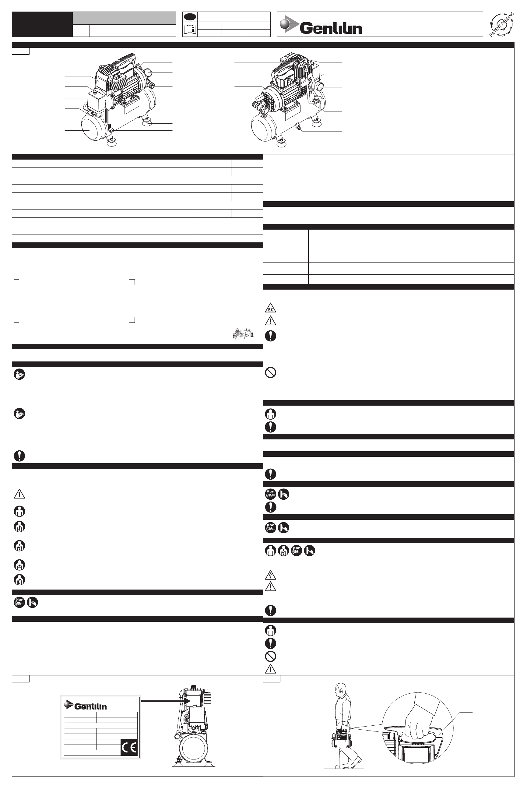
The machine can be carried by an operator using the handle .(FIG. 3 - Ref. 1)
THE MACHINE MUST BE MOVED BY AN OPERATOR IN OBSERVANCE OF THE REGULATIONS GOVERNING THE "MANUAL HANDLING OF LOADS" IN ORDER TO
PREVENT UNFAVOURABLE ERGONOMIC CONDITIONS THAT COULD CAUSE BACK INJURY.
7- STATUS “APPLIANCE OFF”
Before carrying out any type of maintenance and/or regulation operation on the appliance, you must:
Shut off the power supply ensuring that the “ ” switch is in the “OFF (O)” position
Unplug the power cable from the plug located near the appliance;
Empty the tank (no pressure).3)
1) (FIG. 1 - Ref. 3)
2) (FIG. 1 - Ref. 7)
(FIG. 1 - Ref. 14)
ON (I) -OFF (0) ;
4) VALIDITY: the warranty is valid if the buyer notifies the manufacturer of any lack of conformity within 2 months from the date on which the lack
was detected. The above mentioned notification must necessarily be accompanied by a regular proof of purchase (till receipt or invoice).
5) EXPIRY:
6) RESPONSIBILITY:
7) FEES:
the warranty expires in the instance where the Acquirer uses the appliance in an inappropriate and/or in such a way that goes against
the details in the “Instruction Manual” supplied by the Manufacturer, or in the instance where the defect is owing to the inexperience of the
Acquirer or an accident.
the Manufacturer is exempt from all responsibility from harm caused to the Acquirer in terms of lack of or reduced
performance owing to conformity defects.
the fees relative to the work force and materials necessary to restore the appliance are charged to the Manufacturer. The fees and
delivery methods are to be agreed upon with the Authorised Supplier.
8- WARRANTY
1) WARRANTY DECLARATION:
2) ACQUIRER:
3) TERMS:
the Manufacturer guarantees the Acquirer, the replacement, repair and intervention relative to all appliances, where
the aforementioned display conformity defects which comprise correct usage and operation, only where such defects are owing to the fault of
the Manufacturer. The Manufacturer reserves the right to adopt the best solution in order to restore appliance conformity within a
reasonable amount of time.
the Acquirer is defined as a “consumer” where the purchase was made by a physical person and where the appliance is not to be
used for commercial or professional purposes;
The Acquirer is defined as a “professional or company” where the purchase was made by a professional or company who aims to use the
appliance for commercial or professional purposes.
the Manufacturer is responsible where the defect of conformity is discovered within the following time frame from the purchase date:
24 months where the purchase was made by a “consumer” as described under point 2);
12 months where the purchase was made by a “professional or company” as described under point 2).
GENTILIN SRL
Via delle Tezze, 20/22 - 36070 Trissino (VI) ITALY
Tel. +39 0445 962000 - Fax +39 0445 491412
COMPRESSOR B110
MOD. B110/05
FIG. 3
Right side
1
(cont.)
11- INCORRECT USE
The appliance was designed and manufactured exclusively for the aim as described in ; in order to ensure the safety of authorised
operators and appliance efficiency at all times, any other use is completely forbidden.
Paragraph 10
DANGER OF BURNS UPON ACCIDENTAL CONTACT WITH SINGLE-CYCLINDER PUMPING ASSEMBLY AND ELECTRTIC MOTOR. WARNING –RESIDUAL RISK
(SEE PARAGRAPH 22).
IT IS COMPLETELY FORBIDDEN TO OPERATE THE APPLIANCE IN ENVIRONMENTS PRONE TO EXPLOSIONS AND/OR WHERE COMBUSTIBLE SUBSTANCES ARE
PRESENT (E.G. WOOD GRAINS, FLOUR, SUGAR AND GRANULES).
THE MACHINE MUST BE USED IN COMPLIANCE WITH LEGISLATION GOVERNING EMISSIONS (NOISE) IN FORCE IN THE COUNTRY OF USE.
DURING USE, ENSURE THAT UNAUTHORISED PERSONS DO NOT COME WITHIN PROXIMITY OF THE APPLIANCE.
THE APPLIANCE MUST BE KEPT OUT OF THE REACH OF CHILDREN.
IT IS STRICTLY FORBIDDEN TO USE THE MACHINE OUTDOORS.
INCORRECT USE OF THE APPLIANCE OR USE WHICH DIFFERS FROM THAT SPECIFIED IN PARAGRAPH 10 IS FORBIDDEN.
THE USE OF UNSUITABLE AIR PIPES (EXTENSIONS), CONNECTIONS AND UTENSILS OR THOSE WHICH DO NOT CONFORM WITH CURRENT LEGISLATION IN
FORCE ARE COMPLETELY FORBIDDEN.
IT IS FORBIDDEN TO LIFT THE APPLIANCE WITH CRANES AND/OR LIFTING DEVICES.
IT IS FORBIDDEN TO DIRECT COMPRESSED AIR JETS AT PERSONS AND/OR ANIMALS.
IT IS FORBIDDEN TO USE THE APPLIANCE TO MOVE AND/OR LIFT PERSONS, ANIMALS OR OBJECTS.
IT IS FORBIDDEN TO MOUNT THE APPLIANCE.
IT IS FORBIDDEN TO TOW THE APPLIANCE USING ANY TYPE OF MEDIUM AND/OR VEHICLE.
IT IS FORBIDDEN TO MANUALLY MOVE THE APPLIANCE UPHILL AND/OR DOWNHILL WHERE DANGEROUS INCLINATIONS ARE PRESENT.
PLEASE DISPOSE OF THE PACKAGING DIVIDING IT UP ACCORDING TO THE VARIOUS WASTE MATERIALS AND IN COMPLIANCE WITH LEGISLATION
CURRENTLY IN FORCE IN THE COUNTRY OF USAGE.
1)
2)
3)
4)
5)
6)
7)
8)
9)
10)
11)
12)
13)
14)
15)
16)
17)
18)
19)
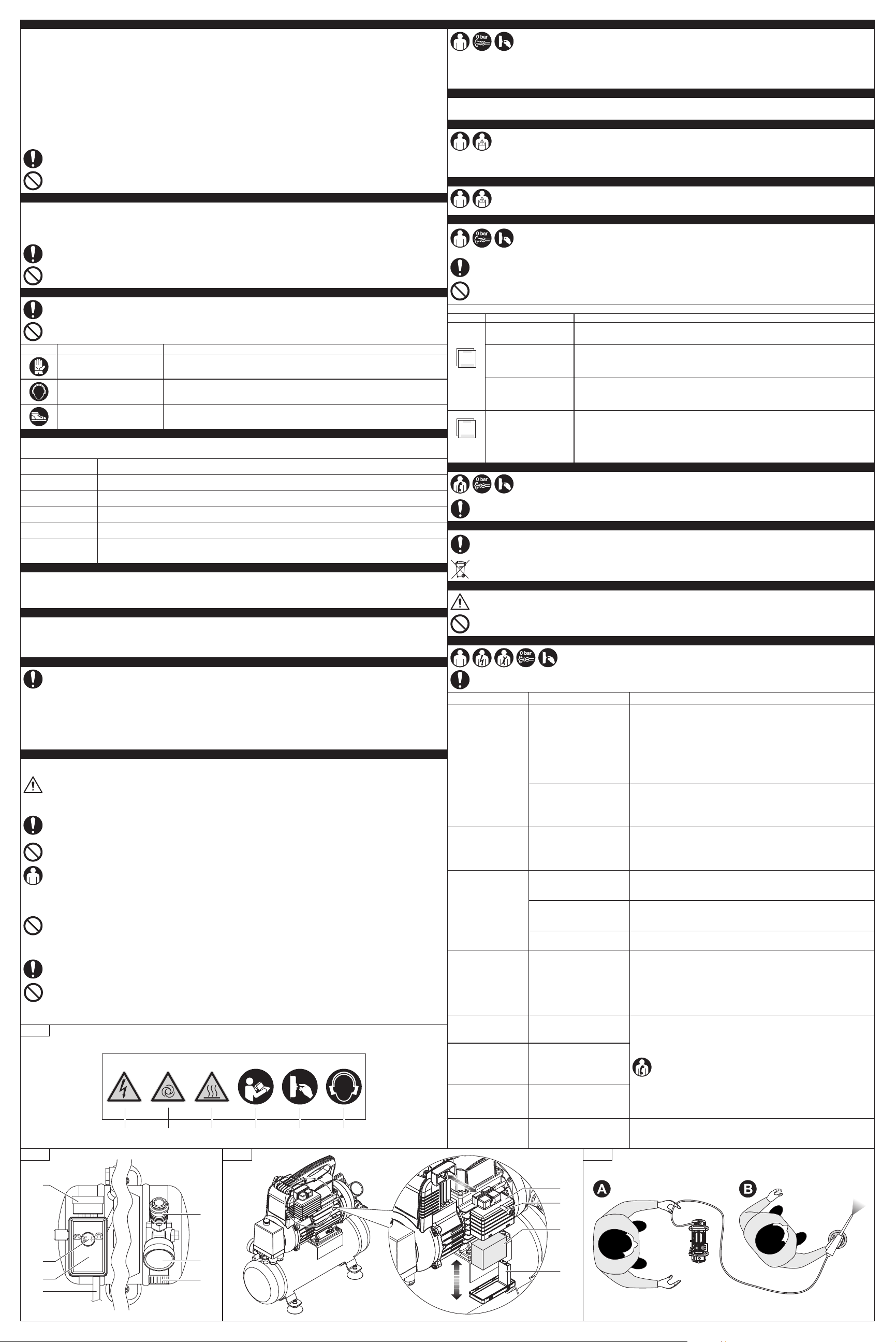
Carrying handle
Air conveyor
ON (I) – OFF (O) switch
Pressure switch
Safety valve (set to 10.5 bar)
Air tank
Power plug and cable
Feet
Outlet pressure regulator
Tank outlet gauge
Air outlet spigot
Air filter
Electric motor
Condensate pump
Pump/Tank connection pipes
Non-return valve
Tank pressure gauge
Fixed cooling fan protective net
Single-cylinder pumping assembly
FIG. 1
RH side view
6
5
3
4
2
7
9
10
11
1
8
LH side view
12
14
17
16
13
19
18
15
Front side
GENTILIN SRL
Via delle Tezze, 20/22
36070 Trissino (VI) ITALY
Tel. +39 0445 962000
Fax +39 0445 491412
TIPO / MODELLO
TYPE / MODEL
ANNO / YEAR
SERIAL NoN° DI SERIE / .
S3
PRESSIONE MAX. ESERCIZIO
MAX. WORKING PRESSURE
VEL. ROTAZIONE ALBERO
SHAFT ROTATION SPEED
POTENZA NOM.
RATED POWER
PESO
WEIGHT
TENSIONE
TENSION
...... rpm
..... V / ..... Hz / ..... A
9 bar
20 min ON / 10 min OFF - 66% ON
........
B110/05
...... kW
kg 12.5
FIG. 2
TRANSLATION OF THE
ORIGINAL INSTRUCTIONS
30.06.11
00
CM11163
EN
Code Issue Revision
INSTRUCTION
MANUAL
1- PARTS LIST
Supply voltage/Frequency
Nominal power
Max. operating pressure
Levelof output noise levels A at the work stations (Leg. 2006/42/CE)
Driveshaft rotation speed
Tank volume
Performance (aspirations/yield)
Temperature/air humidity
Total weight
Dimensions (lxwxh)
/
/
110 - 230 / 50
9
+5 ÷ +40 / 5 ÷ 95
110 / 60
2800
5
12,5
191x414x392
72
110 - 230 / 60
0,5 /
/