genoQs Machines Octopus User manual


Introduction
Welcome, and sincere congratulations to the purchase of your
new sequencer – a genuine genoQs Machines Octopus!
You now own one of the definitely finest MIDI instruments ever
built. We proudly put in your hands a device built to drive your
creativity and provide you joy for years to come.
Octopus is conceived as a living instrument with long-lasting
value, to help you search and un-cover new sonic territory,
rewarding you with an unequalled haptics experience.
We invite you to explore the capabilities of Octopus as you like
and provide this manual as a start-up guide. Herein, you will
recognize many known terms and concepts. However, others
may be used slightly differently from what you would expect
and some may be entirely puzzling.
This is why we recommend that once you are over the first
wave of pushing buttons, flashing lights and turning knobs
you read this guide end-to-end carefully – and we are aware
that no-one likes to read the manual..
Taking a step back, we do appreciate the complexity that
Octopus is able to provide. Don’t get intimidated! You will soon
discover fast ways of operation that best suit your style and
preference, the comfort zone where you are most productive.
But remember that only few clicks away await things that you
had never thought of doing or achieving. This is what Octopus
is about – at every stage and no matter what - you are
encouraged to experiment, explore and push the boundaries!
Please check our web site for the latest software and
documentation at www.genoqs.net
genoQs Machines - April 2007, Stuttgart, Germany

TABLE OF CONTENTS
IOVERVIEW........................................................................................................................................I-0
GENERAL CONCEPTS .......................................................................................................................... I-1
II START-UP ........................................................................................................................................ II-0
CONNECT AND POWER-ON ..............................................................................................................II-1
GENERAL CONTROLS.........................................................................................................................II-3
INTERFACE CONVENTIONS..............................................................................................................II-4
BASIC STEP OPERATION ...................................................................................................................II-5
BASIC TRACK OPERATIONS.............................................................................................................II-7
TRACK CHAINING ............................................................................................................................ II-10
STEP REAL-TIME ENTRY ................................................................................................................ II-12
THE MODE BLOCK............................................................................................................................ II-13
III STEP MODE....................................................................................................................................III-0
BASIC OPERATION ............................................................................................................................ III-1
STEP ATTRIBUTES ............................................................................................................................. III-2
STEP MUTATORS ............................................................................................................................... III-4
STEP SELECTIONS ............................................................................................................................. III-2
IV TRACK MODE ...............................................................................................................................IV-0
BASIC OPERATION ............................................................................................................................ IV-1
TRACK ATTRIBUTES......................................................................................................................... IV-2
TRACK MUTATORS ........................................................................................................................... IV-5
TRACK SELECTIONS ......................................................................................................................... IV-8
TRACK CHAINING ............................................................................................................................. IV-8
TRACK PROGRAM CHANGES.......................................................................................................IV-10
TRACK TEMPO MULTIPLIERS......................................................................................................IV-11
TRACK AUXILIARIES......................................................................................................................IV-13
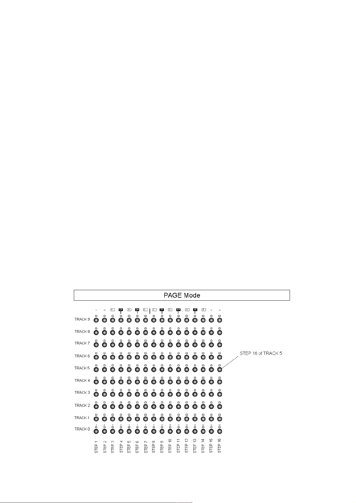
VPAGE MODE.................................................................................................................................... V-0
BASIC OPERATION ............................................................................................................................. V-1
THE MIXER BLOCK ............................................................................................................................ V-2
PREVIEW STATE.................................................................................................................................. V-5
EDITOR ATR STATE............................................................................................................................ V-6
EDITOR MCC STATE........................................................................................................................... V-7
PAGE FUNCTIONS ............................................................................................................................... V-8
BANK VIEW .......................................................................................................................................... V-9
PLAY MODE ........................................................................................................................................ V-10
VI GRID MODE ...................................................................................................................................VI-0
BASIC OPERATION ............................................................................................................................ VI-1
PAGE OPERATIONS ........................................................................................................................... VI-2
PAGE CLUSTERS ................................................................................................................................ VI-3
VII PERFORMANCE TOOLS ..................................................................................................... VII-0
WORKING WITH PAGES ..................................................................................................................VII-1
GRID CC MAPS ...................................................................................................................................VII-3
GRID MODE PAGE MUTES..............................................................................................................VII-4
PAGE SETS...........................................................................................................................................VII-5
GRID-TRACK MODE .........................................................................................................................VII-6
VIII MUSICAL TOOLS .................................................................................................................VIII-1

STEP CHORDS .................................................................................................................................. VIII-2
PAGE SCALES ................................................................................................................................... VIII-7
THE GRID SCALE............................................................................................................................. VIII-9
IX ADVANCED TOPICS ....................................................................................................................IX-0
CUSTOM TRACK DIRECTIONS ....................................................................................................... IX-1
VIRTUAL MIDI CHANNELS ............................................................................................................. IX-6
TRACK ATTRIBUTE MAPS .............................................................................................................. IX-7
STEP EVENTS ....................................................................................................................................IX-11
THE EFFECTOR .................................................................................................................................IX-13
NOTE ATTRIBUTE COMPUTATION ............................................................................................IX-17
XMIDI IN ............................................................................................................................................. X-0
NOTE STREAM RECORDING ............................................................................................................ X-1
CONTROLLER STREAM RECORDING ........................................................................................... X-2
STEP-NOTE RECORDING................................................................................................................... X-3
ADVANCED RECORDING ................................................................................................................. X-4
CONTROLLER MAP LEARNING ...................................................................................................... X-6
EXTERNAL FORCE TO SCALE ......................................................................................................... X-7
EXTERNAL SCALE BUILDING......................................................................................................... X-8
EXTERNAL PROGRAM CHANGE .................................................................................................... X-9
XI GENERAL TOOLS ........................................................................................................................XI-0
UTILITY FUNCTIONS ........................................................................................................................ XI-1
MIDI CLOCK......................................................................................................................................... XI-2
SYSTEM LOAD HANDLING ............................................................................................................. XI-4
INSTRUMENT STATE INTERNAL SAVE....................................................................................... XI-6
EXPORT MEMORY CONTENT TO MIDI........................................................................................ XI-7
OPERATING SYSTEM UPDATE....................................................................................................... XI-9
XII RELEASE NOTES................................................................................................................... XII-0
RELEASE 1.00......................................................................................................................................XII-1
RELEASE 0.98......................................................................................................................................XII-5
KNOWN ISSUES .................................................................................................................................XII-7
LEGEND ...............................................................................................................................................XII-8
XIII TUTORIALS............................................................................................................................XIII-0
MIDI CC CONTROL ......................................................................................................................... XIII-1
LFO-TYPE MODULATIONS / SUPERSTEP ................................................................................. XIII-3
DIRECTION EDITING...................................................................................................................... XIII-6

I-0
I OVERVIEW

I-1
Octopus hierarchy of objects and related attributes
GRID
PAGE 1
Track 0 Step 1
Step 16
PAGE GRID
144 PAGES
1440 TRACKS
23040 STEPS
Track 9 Step 1
Step 16
CC Map 0
CC Map 5
PAGE 144
Track 0 Step 1
Step 16
Track 9 Step 1
Step 16
CC Map 0
CC Map 5
CC Map 0
CC Map 5
VEL
PIT
Velocity
Pitch
VEL
PIT
LEN
STA
POS
DIR
AMT
GRV
MCC
MCH
Velocity
Pitch
Length
Start
Position
Direction
Amount
Groove
MIDI CC
MIDI Channel
VEL
PIT
LEN
STA
AMT
MCC
Velocity
Pitch
Length
Start
Amount
MIDI CC
GENERAL CONCEPTS
This section provides an
introduction to the concepts at
the base of Octopus.
We advise the impatient reader
skipping this to come back to
this section once confusion sets
in and nothing makes sense
anymore.
THE OCTOPUS WORLD
In brief, the Octopus world
consists of entities or objects,
attributes that are associated
with them, and functions that
modify those objects or their
attributes.
The ultimate idea is to allow
modifications of the objects in
the most flexible manner and in
real time, which is done using a
subjectively intuitive control
model and the comprehensive
Octopus user interface.
OCTOPUS OBJECT MODEL
The master Octopus object is the
GRID, which contains PAGES,
each of them containing
TRACKS, which are made up of
STEPS.
Each object is associated with
attributes and functions that
can be operated upon. The
diagram depicts at a high level
the Octopus hierarchy of objects
and their related attributes.

I-2
NAVIGATION BASICS
The Grid contains all Page
objects and any Page is made up
of Tracks and Steps.
As we will also see later, moving
around this hierarchy tree is
trivial: to jump between leaves
you can always go up a level and
down again. However, in most
cases direct paths are also
provided, allowing you to jump
directly from one leaf to another.
MOVING AROUND
Just as an example, assuming
you are in the GRID mode, you
would hold the PAGE button and
select the page you would like to
jump into, by pressing its button.
Or you would double-click on
the corresponding page button.
You would do the same to get
further down into a specific
track and from there into a
specific step. You may also
choose to go from a page into a
step directly, as we will see later.
Navigating back up the tree is
only one click away, and will
take you directly to the selected
level. Or simply use the ESC key
to always get to the PAGE level
of your current page, arriving at
a known starting point.
Similarly, in Track mode, press
TRACK and the selector
corresponding to the track you
would like to jump to. This
works in MAP mode as well. In
Step mode, press and hold STEP
and press a grid button to jump
to the step corresponding to the
pressed button.

I-3
THE GRID
Octopus provides a total of 144
pages grouped in 9 banks of 16
pages each, making up the GRID.
Visually a bank corresponds to
one row of the matrix; hence a
page corresponds to one button
of the matrix. This accounts for
9 rows (row 1-9), with row 0
serving as a grid set selector.
Each bank can be activated for
current play by selecting one of
its (non-empty) pages. This
means that up to 9 pages may
be played concurrently.
Depending on the number of
tracks and the density of the
data, it is possible to overload
the MIDI stream. A more
complete discussion of various
system and MIDI loading is
found in the section on System
Load Handling. See the picture
above for a better understanding
of the Matrix in the Grid mode.
MIDI CONTINUOUS CONTROLLER
(CC) MAPS
The CC Maps are simply
assignments of CC functionality
to the Mixer knobs of Octopus.
You can use CC Maps to freely
assign MIDI Controllers and
their appropriate channels to the
Mixer knobs, independently of
what is going on in the PAGE.
PAGES
One can think of Octopus' pages
as track containers. The number
of tracks in a page is 10, with a
default length of 16 steps each.
See picture.

I-4
Musical structures longer than
16 steps are built by chaining
tracks in a page, such that
chained tracks are played
consecutively.
At a glance, the preset chain
modes available are: 10 tracks of
1 row each (default), 5 tracks of
2 rows each, 2 tracks of 4 rows
each + a track of 2 rows, and 1
track made up of 8 rows + a
track of 2 rows.
However, the user is also free to
build any other track chain
configuration, as desired.
This combined with the ability to
play up to 9 pages concurrently
and each of the 9 pages being
part of a cluster of at most 16
consecutive pages gives you a lot
of room for both composition
and live play.
TRACKS
If pages are Octopus' track
containers, then tracks are the
step containers.
Apart from other attributes, each
track has a locator associated
with it which can be controlled
independently from locators of
other tracks.
STEPS
In Octopus steps are the
smallest meaningful entities, for
example notes in a musical
context.
In track mode the individual
steps of a selected track can be
modified across their available
range of attributes.
MUTATORS
Entities or attributes of entities
can be operated upon using
mutators or functions, for
example clear, randomize,
modify, copy, paste, and others.
While the modify function is
mapped directly to the knobs as
described in the operation mode
section, the others are invoked
by pressing the appropriate
mutator buttons.
ATTRIBUTES
All of the above entities of
Octopus have attributes
associated with them. The range
includes but is not limited to
Velocity, Pitch, Length, Start,
Position, and others.
Generally, attributes can be
modified in real time, during
play or stop. Their semantics
may differ across entities and
Page
Track
Step
VEL
x
x
x
PIT
x
x
x
LEN
x
X
STA
x
x
POS
x
x
DIR
x
AMT
x
x
GRV
x
x
MCC
x
x
MCH
x

I-5
not all attributes are applicable
to all entities.
The attached table gives an
overview of the entities and their
applicable attributes.
ATTRIBUTE MAPS
The attribute maps are basically
views associated with TRACK
objects which will allow you to
view and edit directly the values
of all steps in a track, for a
specific attribute.
For example, the velocity map of
a track will show you at a glance
all step velocities, allowing you
to change them directly by the
press of a button.

I-6
THE FRONT PANEL
The Octopus front panel consists
of visual groups which we will
name and to which we will refer
in the course of this document.
They are explained in a left to
right order.
MIX ENCODERS
Each row has a dedicated left
rotary encoder – in the MIX
(Mixer) group.
SEL BUTTONS
Each row has a dedicated button
in the SEL (Selector) group.
MATRIX
The MATRIX refers to the field of
16x10 buttons.
The buttons take on various
functions, depending on the
operating mode of the sequencer.
The most obvious one is
probably, when matrix rows
represent tracks of 16 steps
each.
Right below the matrix is the
MIX TARGET field which
determines the functionality of
the MIX rotary knobs.
MUT BUTTONS
Each row has a dedicated button
in the MUT (Mutator) group.
Octopus front panel
MIX (mixer) rotary encoders
SEL (selector) buttons
MATRIX field (160 buttons)
MIX TARGET field
MUT (mutator) buttons
EDIT (editor) rotary encoders
MAIN knob
CHORD block
TRANSPORT block
MODE block
SCALE block
OUTER CIRCLE
INNER CIRCLE

I-7
EDIT ENCODERS
Each row has a dedicated right
rotary encoder – in the EDIT
(Editor) group.
CIRCLE
The circle is made of buttons
that provide a range of
functionality that applies across
modes and objects.
Among other controls, the circle
includes the SCALE, MODE,
TRANSPORT, and CHORD fields
and the MAIN knob.
Each of the listed building
blocks of the front panel takes
on specific functions according
to the operational mode active at
any point in time.
NOTE:
First and foremost we are asking
that you familiarize yourself with
the front panel layout, so we can
refer to buttons and LEDs as we
go along. The miniature picture
provided should be enough as an
orientation, since you have the
real thing in front of you.
ADDITIONAL CONTROLS
Beside the front panel controls
there are two other important
buttons:
The power-on button is located
next to the power plug on the
back side of the unit. No further
explanation necessary.
The reset button is located
under the main Octopus panel
just under the Main knob. The
red reset button does what the
name suggests – it will simply
reboot your machine, by default
resetting it to the last saved
state.

II-0
II START-UP

II-1
CONNECT AND POWER-ON
Start simply by connecting just
one sound source to the MIDI
OUT 1 port and then use the
provided power cord to connect
Octopus to a power outlet.
POWER SUPPLY
Octopus has an auto-sensing
110-240 Volt (50-60Hz) power
supply so you can safely power it
up in any country without extra
adapters or converters. All you
need is a cable that fits your
power outlet, and that should
have come with your machine
already.
SOUND SOURCE
Set your sound source to receive
on channel 1 and also choose a
pitched sound with a medium
release time. Something like
piano may be suitable, but don’t
feel constrained in any way.
POWER-ON
Power on the unit by flipping the
power switch.
USB LAMP
If you have connected a USB
lamp in the port labelled “Lamp”,
you should see it turn on
immediately, and about two
seconds later you should see
some of the front panel LEDs
turn on.
The LED labelled PAGE should
be blinking orange.
Congratulations – you are now
ready to engage on a long and
rewarding journey with your new
sequencer!
START
Upon power-on (or reset),
Octopus starts in the state that
was last saved to its internal
FLASH (non-volatile) memory.
When you are powering up the
machine for the first time, or
after a memory refresh, the
machine is starting up with its
“factory default” values.
START-UP DEFAULTS
The defaults include having the
master tempo at 120bpm, all
tracks running on direction 1,
all tracks set to send on MIDI
channel 1 of port 1, and a
particular pitch assignment for
tracks 0-9 as follows:
C3, D3, E3, G3, A3, C5, D5, E5,
G5, and A5. Octopus may be
reset to this default condition at
any time during operation.
RESETTING TO START-UP
DEFAULTS
Please note that doing this will
erase any changes you have
made and possibly want to keep,
so use this with extreme
caution: the procedure is to

II-2
press and hold the GRID mode
button, while pressing the CLR
button.
Again, this only clears the RAM
(volatile) memory contents and
leaves the content of the FLASH
(non-volatile) memory untouched.
BYPASSING STATE RELOAD
By the same token, if you hold
the CLR button down while
powering up the machine,
Octopus will not load the FLASH
memory contents, but will
simply start with the factory
defaults.

II-3
GENERAL CONTROLS
Octopus features a set of
transport buttons, which are no
different from what you may
know from other devices. Start,
Stop and Pause functions are
available.
PLAY
Press any of the play buttons in
the transport section as depicted.
It makes no difference which one
you press as long as they show
an arrow in their label. The
difference between them will
appear later, so please bear with
us for a moment.
You should now see the red
chase light move across the
matrix.
If you do not hear anything, it is
because you have not yet set any
steps to play.
STOP
You may now want to stop the
sequencer – do that by pressing
the stop button – as labelled.
Stopping the sequencer will reset
the chase light position to zero.
PAUSE
Once the sequencer is playing,
you may also pause it – by
pressing the pause button – as
labelled.
The pause button freezes the
chase light at the current step.
To continue from pause (to un-
pause) you may press pause
again, or any of the play buttons.
You may want to play a bit with
the transport buttons to get
yourself familiar with how they
work.
MASTER TEMPO
Before you continue, you may
want to set a different master
tempo for the sequencer.
Simply turn the MAIN rotary
encoder in the top right corner –
clockwise (increase) or counter-
clockwise (decrease).

II-4
INTERFACE CONVENTIONS
NUMBER DISPLAY CONVENTION
Two other things to notice here:
the LED of the button labelled
Tempo is orange – this indicates
that the encoder is regulating
the tempo.
As you turn the knob, you will
see funny things happen to the
lights of the top left quadrant of
the outer circle. This part of the
panel is used to indicate the
current master tempo and
display its value. Do what?
Yes – the red dots have to be
understood as multiple of tens,
the green dot represents the
value of ones in the number on
display. Plus there is another
red light potentially lighting up,
labelled 100. That adds 100 to
the number.
For example, 143 would be
represented by the LEDs 100, 1,
2 and 4 lighting red, and 3
lighting green.
One exception to the rule is
numbers where the tens and the
one are the same digit - in that
case the digit in question will
light orange. For example 77 will
be displayed as 7 LEDs with
LED 1-6 lighting red and LED 7
lighting orange.
Experiment a bit with this and
you will get a good feel for this
representation quickly. You will
re-encounter it at many other
occasions as we move along.
CLICK CONVENTION
While we are here, we can
introduce another convention:
the click convention.
You can directly select a value
by pressing the buttons in the
tempo area. Double click on a
number to set the ten’s (red)
value and single click to set the
one’s (green) value.
For example double click on 7
and single click on 2 to set a
tempo of 72. Note that by just
double clicking on a number, the
ones value is set to zero.
This makes it very quick and
easy to select round values like
60, 80, or 120. Selecting non-
round values is just one more
click away.
As with the number display
convention, the click convention
is used all across the
instrument’s interface, so we will
run into it again, soon enough.

II-5
BASIC STEP OPERATION
STEP TOGGLE
The orange blinking PAGE LED
in the MODE field indicates that
you are now in the PAGE mode.
For now it is enough to know
that in this mode every row in
the matrix represents a track,
and every button represents a
note or a step. This is no
different as you would probably
expect anyways, knowing that
Octopus is a chase-light pattern
sequencer. Let’s press some
buttons now.
Press any of the matrix buttons,
and you will see the steps go on,
indicated by the green lights
going on. Pressing active steps
will deactivate them, turning
them off again.
Make sure that you set your
connected sound device to MIDI
Channel 1. If you do, you should
hear sound played by your
synthesizer.
STEP SKIP
Toggling steps as we have seen
before is sure fine – another
thing you may want to do
though, is skipping steps
entirely. Skipping a step means
that the chase-light will simply
ignore the step and just move to
the next un-skipped one.
To skip a step, press and hold
the MUT button (shown) while
you press the button of the step
that you want to skip. You will
see the step LED turn
red. Repeat the
procedure for as
many steps as you
would like.
To un-skip a step and make it
plays again in the regular
fashion, just press it by itself
and you should see its light go
off. Press it a second time - as
long as you don’t hold the MUT
button pressed, you will see it
toggle on as an active step.
STEP TWEAKING
Use what you have learned so
far to compose a pattern in one
of the tracks.
Start the sequencer and you will
hear the pattern played, boring
as it is, since all steps are set to
a default level.
Let’s change that, but tweaking
some Step attributes. We will
use PIT here as an example.
Just “grab” a Step by pressing
its button and keeping it pressed
(it doesn’t matter if it’s originally
on or off). Now turn the PIT
rotary encoder clockwise to
increase the pitch of the step.

II-6
Turning PIT counter-clockwise
will decrease the pitch – one
half-tone per encoder click.
The PIT rotary is the second one
from the top of the EDIT block.
You will now hear that the pitch
of the step has changed every
time the chase-light passes it.
Feel free to experiment as you
wish, with other attributes and
refer to the section on STEP
mode for details.
Grab other steps and play
around until you shape your
pattern into something you like
before moving on.
GHOST TOGGLE
Press and hold pressed two or
more step buttons placed in
separate rows. Let’s use for
instance the rows 4 and 5.
Press a step in row 4 and at the
same time a step in row 5 – and
make sure you do not release
the buttons yet.
Now toggle steps in row 4 – and
you will see that the steps in the
same column of row 5 will be
toggled as well. We call this
behaviour “ghost toggle”.

II-7
BASIC TRACK OPERATIONS
Since you now have a pattern
you like, but still want to explore,
let’s make an identical copy of
your track pattern first and then
modify the copy while keeping
the original safe.
On the left side of the
Octopus panel you see
a block called SEL, to
the right of the MIX
rotary encoder block.
These are the Selector
buttons.
Symmetrically to the
right you see another
block called MUT, to
the left of the EDIT
rotary encoder block.
These are the Mutator
buttons.
For now we will use the selector
button corresponding to our
track to “grab” it, and do
something – in this case copy it.
TRACK COPY
Go ahead and press the track
selector button of the
corresponding TRACK and keep
it pressed. You will see some
changes in the LED pattern of
the panel; don’t worry about it
for now. You will see that once
you have grabbed a track, the
mutator block becomes active
and you see that the CPY
mutator is now lit orange.
Press the CPY mutator and
release the track (move your
finger off the selector). You have
just copied the track you have
grabbed to an internal buffer*.
TRACK PASTE
Now grab an empty track as
described above by pressing its
selector and keeping it pressed.
You will notice that paste is now
available, indicated by the lit
PST mutator. Press the PST
mutator to paste the contents of
your source track into the
destination.
* NOTE: you have not copied the
full track data, but only a
reference to it. This means that at
the time of the paste operation
you will get the most recent data
of the just copied track and not
the data at the time of the copy
operation. Therefore, any
changes between the copy and
the paste operation are
permanent and not recoverable.
TRACK MUTE
The result of the previous copy
and paste operation is that you
now have two identical tracks in
the same page. So all you got is
just an annoying double-trigger
of your pattern (audible
Table of contents
Other genoQs Machines Recording Equipment manuals