User responsibility
Your fire alarm system should
have been designed, installed and
commissioned to your site specific
requirements and in accordance
with the requirements of BS5839
Part 1. You should have received
instructions about your system
during the handover stage and
must make arrangement to ensure
the system is regularly tested and
maintained.
It is recommended that the
person responsible for the fire
alarm system should ensure the
system is tested and maintained in
accordance with the requirements
of BS5839 Part 1 and become
familiar with:
qhow to operate the controls and
interpret the indications given at
the control panel and
qkeep up to date all
documentation associated with
the system.
CAUTION: Any servicing
work on the fire alarm
system must be carried out
by a suitably trained person,
refer to your servicing
organisation.
Daily
BS 5839:Part 1, states that the
system should be inspected daily
to ensure:
qthat a normal indication is given
at the control and indicating
equipment.
qthat any previously indicated
fault condition has received
appropriate attention.
qall the system events are
entered into the Log Book for
future reference.
qthat the use of the area(s)
inspected has not changed
since the system was designed.
qThat no unsafe practices that
could lead to fire are being
undertaken.
Weekly
When testing the system there
may be a need to isolate ancillary
outputs and to contact the alarm
receiving centre before and after
the weekly test.
qA different manual call point of
the system should be tested to
ensure the system is capable of
operating under alarm
conditions.
qThe operation of the alarm
should be checked to remind
those occupying the premises
that there is a fire alarm system
with a particular sound.
NOTE: The test should be
performed at a regular time to
avoid confusion between a test
and a genuine fire alarm. The
alarm receiving centre must be
contacted before and after the
test to check alarms are
received and also to avoid
unwanted alarms.
Quarterly
At quarterly intervals the system
should be inspected and any work
necessary should be performed by
a trained maintenance engineer.
NOTE: For help with service
and maintenance please refer to
your servicing organisation, see
contact details entered in the
log book.
Limitation of false alarm
It is recommended that the person
responsible for the fire alarm
system should arrange for suitable
investigation and appropriate
action on occasion of every false
alarm. For a system having less
than 40 automatic fire detectors
installed, an in-depth investigation
should be instigated on
occurrence of two false alarms in
any rolling 12 months. For a
system having more than
40 automatic fire detectors an
investigation should be instigated
if there has been:
qone false alarm for every 20
detectors installed in the system
in any rolling 12 months, or
qtwo or more false alarm
occurrence from a single
device.
Battery Replacement
NOTE: Any servicing work on
the System must be carried out
by a servicing organisation.
Under normal operating conditions
the maintenance free lead acid
batteries in the Control and
Repeat panels can have a useful
life of up to 5 years from the date
of manufacture.
NOTE: It is recommended that
these batteries are replaced at
4 Yearly intervals from the date
the System is first
commissioned.
CAUTION: The batteries should
only be replaced by trained
service personal.
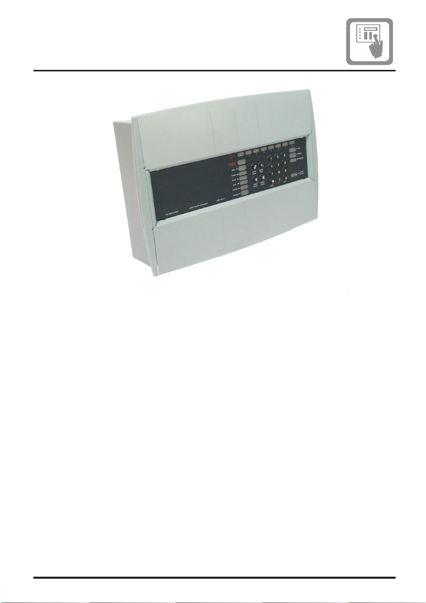
Fire Panels
4188-424 issue 8_Part 2_07-14_Xenex 2
www.acornfiresecurity.com
www.acornfiresecurity.com