Gentec-E PH100-Si User manual

Warranty
First Year Warranty
The Gentec-EO power and energy detectors carry a one-year warranty (from date of shipment) against
material and /or workmanship defects when used under normal operating conditions. The warranty does
not cover recalibration or damages related to misuse.
Gentec-EO will repair or replace at its option any wattmeter or joulemeter which proves to be defective
during the warranty period, except in the case of product misuse.
Any unauthorized alteration or repair of the product is also not covered by the warranty.
The manufacturer is not liable for consequential damages of any kind.
Customers must fill in and mail the warranty card in order to validate the warranty.
In the case of a malfunction, contact the local Gentec-EO distributor or nearest Gentec-EO office to obtain
a return authorization number. Return the material to the appropriate address below.
Contacting Gentec Electro-Optics Inc.
To help us answer your calls more efficiently please have the model number of the detector you are
using readybefore calling Customer Support.
All customers:
Gentec-EO, Inc.
445 St-Jean-Baptiste, Suite 160
Quebec, QC, G2E 5N7
Canada
Tel: (418) 651-8003
Fax: (418) 651-1174
Email: service@gentec-eo.com
Web: www.gentec-eo.com
Lifetime Warranty
Gentec-EO will warranty any power and energy detector head for its lifetime as long as it has been
returned for recalibration annually from the date of shipment. This warranty includes parts and labor for all
routine repairs including normal wear under normal operating conditions.
Gentec-EO will inspect and repair the detector during the annual recalibration. Exceptions to repair at
other times will be at Gentec-EO’s option.
Not included is the cost of annual recalibration or consequential damages from using the detector.

Version 2.0 ii
PH Series Instruction Manual Gentec Electro-Optics Inc. All rights reserved
The only condition is that the detector head must not have been subject to unauthorized service or
damaged by misuse. Misuse would include, but is not limited to, laser exposure outside Gentec-EO’s
published specifications, physical damage due to improper handling, and exposure to hostile
environments. Hostile environments would include, but are not limited to excessive temperature,
vibration, humidity, or surface contaminants; exposure to flame, solvents or water; and connection to
improper electrical voltage.
TABLE OF CONTENTS
WARRANTY.....................................................................................................................I
First Year Warranty ....................................................................................................................................................i
Lifetime Warranty........................................................................................................................................................i
TABLE OF CONTENTS..................................................................................................II
LIST OF ILLUSTRATIONS............................................................................................III
LIST OF TABLES..........................................................................................................III
1 PH SERIES PHOTO DETECTORS ............................................................................1
1.1 INTRODUCTION ................................................................................................................................................1
1.2 PHOTO DETECTOR CONNECTORS...............................................................................................................2
1.2.1 DB-15 “intelligent” connector ........................................................................................................................2
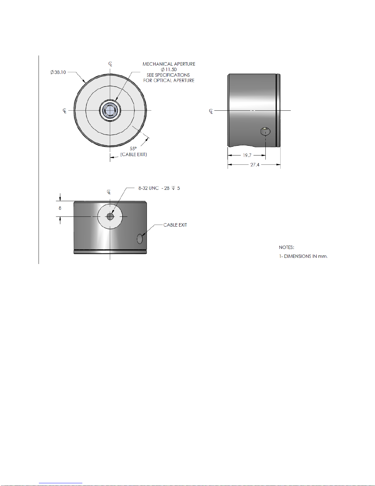
1.2.2 Dimensions .....................................................................................................................................................3
1.3 PH SERIES SPECIFICATIONS..........................................................................................................................4
1.4 PH-B SERIES SPECIFICATIONS......................................................................................................................6
1.5 PE-B SERIES SPECIFICATIONS ......................................................................................................................7
2 OPERATING INSTRUCTIONS............................................................................................................................8
2.1 WITH GENTEC-EO MONITORS.....................................................................................................................8
2.2 QUICK POWER MEASUREMENT PROCEDURE........................................................................................8
3 DAMAGE TO THE OPTICAL ABSORBER MATERIAL.............................................9
4 ERROR SOURCES.....................................................................................................9
4.1 OFFSET.................................................................................................................................................................9

Version 2.0 iii
PH Series Instruction Manual Gentec Electro-Optics Inc. All rights reserved
4.2 OFFSET DRIFT DUE TO TEMPERATURE ...................................................................................................9
4.3 SATURATION....................................................................................................................................................11
4.3.1 Procedure with a known transmission value filter..........................................................................................11
4.3.2 Attenuator calibration procedure ...................................................................................................................11
4.4 MEASUREMENT OF THE AVERAGE POWER OF A PULSE LASER BEAM.......................................11
4.5 WAVELENGTH.................................................................................................................................................11
4.5.1 Example........................................................................................................................................................12
LIST OF ILLUSTRATIONS
FIG. 1-1 PHOTO DETECTOR DIMENSIONS...........................................................................................................3
FIG 1-2 TYPICAL GE TEMPERATURE DEPENDENCE VS THE WAVELENGTH...........................................10
FIG 1-3 TYPICAL SI AND SIUV TEMPERATURE DEPENDENCE VS THE WAVELENGTH.........................10
FIG. 1-4 PH100-SI TYPICAL SPECTRAL RESPONSE..........................................................................................13
FIG. 1-5 PH100-SIUV, PH10B-SI, PE10B-SI TYPICAL SPECTRAL RESPONSE................................................13
FIG. 1-6 PH20-GE, PH5B-GE, PE5B-GE TYPICAL SPECTRAL RESPONSE.....................................................14
LIST OF TABLES
TABLE I. MEASURING RANGES OF GENTEC-EO PH PHOTO DETECTORS...................................................1
TABLE II. MEASURING RANGES OF GENTEC-EO PH-B AND PE-B PHOTO DETECTORS...........................1
TABLE III. THE DB-15 CONNECTOR PIN-OUT.....................................................................................................2
TABLE IV. PH SERIES SPECIFICATIONS FOR GENTEC-EO MONITORS.........................................................4

Version 2.0
PH Series Instruction Manual Gentec Electro-Optics Inc. All rights reserved
1
1 PH SERIES PHOTO DETECTORS
1.1 INTRODUCTION
The Gentec-EO PH Series photo detector family includes three photo detectors sensors (PH100-Si,
PH100-SiUV and PH20-Ge).
The PH100-Si detectors use a silicon photodiode. The PH100-SiUV detectors also use a silicon
photodiode but have enhanced sensitivity at shorter wavelengths. The PH20-Ge detectors use a
germanium photodiode. All three detector heads are 27.4mm thick by 38.1 mm in diameter.
Table I. Measuring ranges of Gentec-EO PH photo detectors
Configuration
PH100-Si series
PH100-SiUV series
PH20 series
Detector alone
0.6 nW to 30 mW
0.6 nW to 2.8 mW
2 nW to 30 mW
With OD-1 attenuator
6 nW to 300 mW
6 nW to 25 mW
20 nW to 300 mW
With OD-2 Attenuator
60 nW to 750 mW
60 nW to 30 mW
200 nW to 500 mW
Note: quoted maximum ranges are average power at the 1064 nm wavelength for PH100-Si and PH20-Ge, 532 nm for
PH100-SiUV, and 850 nm for PH100-SiUV with OD-2
quoted minimum ranges are average power at the 980nm for PH100-Si, 850 nm for PH-100-SiUV and 1550 nm for
PH20-Ge
Table II. Measuring ranges of Gentec-EO PH-B and PE-B photo detectors
PH10B-Si →
50pW to 200µW
PE10B-Si →
1.5 pJ to 0.16µJ
PH5B-Ge →
10pW to 32µW
PE5B-Ge →
500 fJ to 3.2nJ
Note: quoted maximum ranges are average power at the 1047 nm wavelength for Ge and In
quoted minimum ranges are average power at the 633nm for Si. The M-Link was used for those ranges.
The PH and PE series are supplied with a 180 cm long flexible cable terminated with a DB-15
"intelligent" male connector, for use with Gentec-EO Monitors.
NOTE: To eliminate possible damage, do not carry the detector using the connector cable.
The PH and PE photo detectors may also be supplied with a stand.
Call your nearest Gentec-EO distributor to replace the sensor
or to recalibrate the head. See p. ii,
Contacting Gentec Electro-Optics Inc.

Version 2.0
PH Series Instruction Manual Gentec Electro-Optics Inc. All rights reserved
2
1.2 PHOTO DETECTOR CONNECTORS
1.2.1 DB-15 “intelligent” connector
The DB-15 male "intelligent" connector contains an EEPROM (Erasable Electrical Programmable
Read-Only Memory) that stores information such as the model of the detector, the calibration
sensitivity of the available spectral range with or without attenuator and the applicable scales for
that specific PH and PE Series head. Wavelengths are not available where the sensor physical
properties don’t allow it.
The Gentec-eo monitors use the data in this connector to adjust their characteristics automatically
to the power sensor being connected. No calibration procedure is required when installing the
power heads, allowing for faster set-up.
Table III. The DB-15 connector pin-out
1- USED BY MONITORS
2- " " "
3- " " "
4- " " "
5- " " "
6- + Output signal
7- ‘’-’’ SUPPLY VOLTAGE PH-B/PE-B ONLY
8- USED BY MONITORS
9- ‘’+’’ SUPPLY VOLTAGE PH-B/PE-B ONLY
10- USED BY MONITORS
11- " " "
12- " " "
13- - Output signal
14- USED BY MONITORS
15- " " "
SHELL - BODY GRND
NOTE : Consult Gentec-Eo for supply voltage requierements
This manual suits for next models
18
Table of contents