Gentec-EO HP-BLU Series User manual

HP-BLU User Manual Revision 1.0 i
(Cover page to be inserted here)

HP-BLU User Manual Revision 1.0 ii
WARRANTY
The Gentec-EO HP-BLU Laser Power Detector carries a one-year warranty (from date of shipment) against
material and/or workmanship defects when used under normal operating conditions. The warranty does not
cover recalibration, or damages related to misuse.
Gentec-EO will repair or replace at our option any HP-BLU which proves to be defective during the warranty
period, except in the case of product misuse.
Any attempt by an unauthorized person to alter or repair the product will void the warranty.
The manufacturer is not liable for consequential damages of any kind.
In the case of a malfunction, contact your local Gentec-EO distributor or the nearest Gentec-EO office to
obtain a return authorization number. Return the material to the address below.
Contacting Gentec Electro-Optics Inc.
Gentec Electro-Optics, Inc.
445, St-Jean-Baptiste, Suite 160
Québec, QC
Canada, G2E 5N7
Tel: (418) 651-8003
Fax: (418) 651-1174
E-mail: service@gentec-eo.com
Website: gentec-eo.com
CLAIMS
To obtain warranty service, contact your nearest Gentec-EO agent or send the product, with a description
of the problem, transportation and insurance prepaid, to the nearest Gentec-EO agent. Gentec-EO Inc.
assumes no risk for the damage in transit. Gentec-EO Inc. will, at its option, repair or replace the defective
product free of charge or refund your purchase price. However, if Gentec-EO Inc. determines that the
failure is caused by misuse, alterations, accident or abnormal condition of operation or handling, you will
be billed for the repair and the repaired product will be returned to you, transportation prepaid.

HP-BLU User Manual Revision 1.0 iii
SAFETY INFORMATION
Do not use the HP-BLU if the device or the detector looks damaged, or if you suspect that the HP-BLU is
not operating properly.
This device is water-cooled. Water-cooling must be installed before operating the device. Refer to the
instructions for more information. The user must wait for the device to cool before handling after laser
power is applied. The surface of the detector gets very hot and there is a risk of injury if it is not allowed to
cool down.
Note: This equipment has been tested and found to comply with the limits for a Class A digital
device, pursuant to part 15 of the FCC Rules. These limits are designed to provide
reasonable protection against harmful interference when the equipment is operated in a
commercial environment. This equipment generates, uses, and can radiate radio frequency
energy and, if not installed and used in accordance with the instruction manual, may cause
harmful interference to radio communications. Operation of this equipment in a residential
area is likely to cause harmful interference in which case the user will be required to correct
the interference at his own expense.
Caution: Changes or modifications not expressly approved in writing by Gentec Electro-Optics Inc.
may void the user’s authority to operate this equipment.

HP-BLU User Manual Revision 1.0 iv
TABLE OF CONTENTS
1. HP-BLU laser detector .........................................................................................1
1.1. Introduction.......................................................................................................... 1
1.2. Included with your HP-BLU .................................................................................1
1.3. Description of main features................................................................................2
1.3.1. DB-15 connector..........................................................................................................................2
1.3.2. USB connector.............................................................................................................................2
1.3.3. Analog cable (M12 connector).....................................................................................................3
1.3.4. RS-232 cable (standard DB-9 connector) ...................................................................................3
1.3.5. Bluetooth......................................................................................................................................3
1.3.6. Button...........................................................................................................................................4
1.3.7. LED..............................................................................................................................................4
1.3.8. Water-cooling...............................................................................................................................5
1.3.9. Anticipation algorithm ..................................................................................................................6
1.3.10. Alarms........................................................................................................................................6
1.4. Specifications......................................................................................................7
2. Operating Instructions.........................................................................................8
2.1. Installing the USB Driver .....................................................................................8
2.2. Quick Measurement Procedure...........................................................................8
3. User Interface .......................................................................................................8
4. Serial Communication .........................................................................................9
4.1. Description .......................................................................................................... 9
4.2. Setting up Communication to the HP-BLU ..........................................................9
4.2.1. Verify the COM Port.....................................................................................................................9
4.2.2. Connect the HP-BLU ...................................................................................................................9
4.3. Serial Command Format ................................................................................... 10
4.4. List of Serial Commands for the HP-BLU.......................................................... 11
4.5. Detailed Description of the Serial commands For HP-BLU ............................... 12
4.5.1. Data Acquisition.........................................................................................................................12
4.5.2. Setup..........................................................................................................................................13
4.5.3. Control .......................................................................................................................................14
4.5.4. Instrument and Detector Information.........................................................................................17
4.6. Error Messages................................................................................................. 19
5. Declaration of Conformity .................................................................................20
Appendix A –WEEE Directive....................................................................................23

HP-BLU User Manual Revision 1.0 1
1. HP-BLU LASER DETECTOR
1.1.INTRODUCTION
To obtain full performance from HP-BLU, we recommend that you read this manual carefully.
The HP-BLU laser detectors are a variant of the HP series of high-power laser detectors, which also include
a wireless (Bluetooth) signal output. These specialized instruments provide accurate optical power
measurements for demanding high power applications. Using Gentec-EO proprietary calorimetric
measurement, excellent accuracy is attained across a wide range of laser powers. For convenience, the
power measurements can be transmitted wirelessly to your PC, removing the necessity of running a long
wire. The HP-BLU is powered by an internal, long-lasting lithium-ion battery that can last for 24 hours of
operation before needing to recharge.
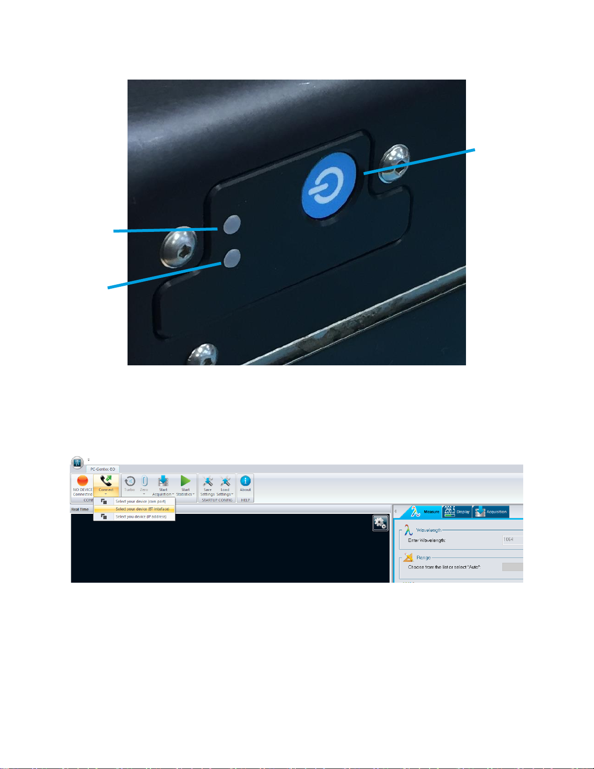
By default, the HP-BLU communicates the laser power measurement over Bluetooth or with a USB cable
to your PC. However, it is also possible to install one of the following cables to allow an additional
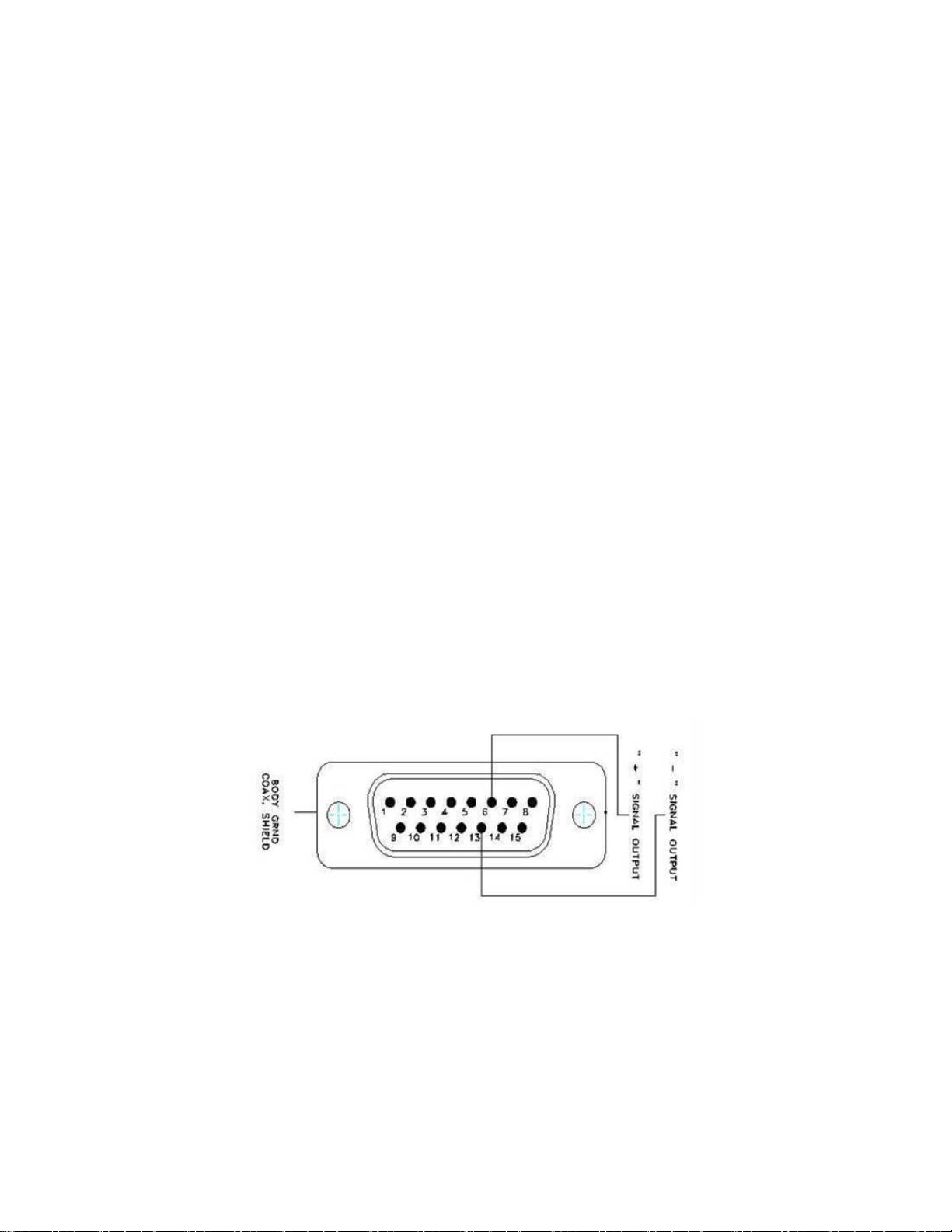
communication interface: a DB-15 cable, an RS-232 cable and an analog cable. The DB-15 cable allows
the HP-BLU to interface with other Gentec-EO monitors. An RS-232 cable with a DB-9 connector can be
installed to maintain compatibility with legacy systems. Finally, an analog cable with an M12 connector is
available for 0-12 V analog output.
The Gentec-EO HP-BLU series power detector family includes HP100A-4KW-HE-BLU, HP60A-15KW-GD-
BLU and HP100A-12KW-HD-BLU, HP125A-15KW-HD-BLU.
When relevant, the same specifications apply to beam dump versions: BD-4KW-HE and BD-12KW-HD.
- The HP100A-4KW-HE-BLU detector has dimensions of 127 mm x 127 mm and an aperture of
100 mm Ø.
- The HP100A-4KW-HE-TUBE-BLU detector has dimensions of 127 mm x 127 mm and a back-
reflection reducing tube with an aperture of 70 mm Ø.
- The HP60A-15KW-GD-BLU detector has dimensions of 153 mm x 153 mm and an aperture of
60 mm Ø.
- The HP100A-12KW-HD-BLU detector has dimensions of 127 mm x 127 mm and an aperture of
100 mm Ø.
- The HP100A-12KW-HE-TUBE-BLU detector has dimensions of 127 mm x 127 mm and a back-
reflection reducing tube with an aperture of 70 mm Ø.
- The HP125A-15KW-HD-BLU detector has dimensions of 153 mm x 153 mm and an aperture of
125 mm x 125 mm.
The high-power surface absorber sensors are designed for use at high average power densities.
The HP detectors can measure between
- 100 W and 4 kW of average power for HP100A-4KW-HE-BLU & HP100A-4KW-HE-TUBE-BLU
- 500 W and 15 kW of average power for HP60A-15KW-GD-BLU
- 300 W and 12 kW of average power for HP100A-12KW-HD-BLU & HP100A-12KW-HD-TUBE-BLU
- 500 W and 15 kW of average power for HP125A-15KW-HD-BLU
For lower power, consult Gentec-EO.
Easy software upgrade
Keep in touch with the latest improvements to our user-friendly software. You can download the latest
software version anytime from our website www.gentec-eo.com and install it on your PC.
1.2.INCLUDED WITH YOUR HP-BLU
Each HP-BLU comes with a Bluetooth USB dongle and a 5-meter USB cable. If you selected one of the 3
optional cables, the HP-BLU will come hardwired with it.

HP-BLU User Manual Revision 1.0 2
1.3. DESCRIPTION OF MAIN FEATURES
1.3.1. DB-15 connector
The optional DB-15 male connector contains an EEPROM (Electrically Erasable Programmable Read-
Only Memory) with different information related to the HP-BLU series detector head in use: detector
model, calibration sensitivity, applicable scales and wavelength correction factor for up to 20
wavelengths.
This connector, available in the HP-BLU, allows the U-LINK, P-LINK, S-LINK, SOLO 2, UNO, TUNER,
MAESTRO monitors to adjust their characteristics automatically according to the power detector being
connected. No calibration procedure is required when installing the power heads, allowing for faster
set-up.
The DB-15 connector pin-out is composed of (see Fig. 1):
1- USED BY MONITOR
2- " " " " "
3- " " " " "
4- " " " " "
5- " " " " "
6- SIGNAL +
7- USED BY MONITOR
8- " " " " "
9- " " " " "
10- " " " " "
11- " " " " "
12- " " " " "
13- SIGNAL -
14- USED BY MONITOR
15- " " " " "
SHELL - BODY GROUND
Figure 1 DB-15 pin-out diagram
1.3.2. USB connector
The USB connector allows using the HP-BLU on a PC. It is a USB type B connector on the HP-BLU. The
PC interface, PC-Gentec-EO, features statistical calculation, graphics displays and data logging options. It
also gives real time measurement of the cooling flow rate and temperature.
A standard 5-meter USB cable is supplied with the HP-BLU. If a longer cable is required, please contact
Gentec-EO for more information.
In some particular cases, the HP must be powered with a USB power supply. For example, when a DB15
extension is used between a HP and a Gentec-EO monitor, or if the DB15 connector is used for analog

HP-BLU User Manual Revision 1.0 3
reading and is not connected to a Gentec-EO monitor. This USB power supply is also required when the
RS-232 cable is used.
The USB power adapter (201221) can be ordered with the required AC plug: USA (201222), UK (201223),
Europe (201224) and Australia (201225).
1.3.3. Analog cable (M12 connector)
An optional configuration allows an analog output up to 12 VDC. This output is only available if the customer
supplies 12 to 24 V to the HP-BLU. This output is only available upon request. Contact Gentec-EO for
details. Please refer to table 1 for the M12 connector pin out:
Table 1 M12 orientation A pin-out
M12 Connector pin 1
Power supply V+, 12 to 24 V
M12 Connector pin 2
Power supply V-, Ground
M12 Connector pin 3
Not connected
M12 Connector pin 4
0-12 V signal, referenced to ground
1.3.4. RS-232 cable (standard DB-9 connector)
An optional configuration allows RS-232 communication to the HP-BLU. RS-232 is often used in legacy
systems. Gentec-EO recommends using USB communication interface instead of RS-232 whenever
possible. For reference, the pin-out of the DB-9 female connector on the HP-BLU is given here:
Table 2 RS-232 DB9 cable pin-out
Pin Number
Signal
1
No Connection
2
TX
3
RX
4
No Connection
5
Signal GND
6
Do Not Connect (Reserved)
7
No Connection
8
No Connection
9
No Connection
TX: Data transmitted from the HP-BLU (output)
RX: Serial commands received by the HP-BLU (input)
Figure 2 DB9: View looking into female connector on the RS-232 cable
1.3.5. Bluetooth
To use the Bluetooth signal, the supplied Bluetooth USB dongle must be plugged in a computer. Verify that
the HP-BLU is on by looking at the LED. If the LED is flashing with the blue colour rapidly, this means that
the HP-BLU is ready to be connected to a computer. If not, press the button on the HP-BLU to turn it on.

HP-BLU User Manual Revision 1.0 4
Please refer to section 1.3.6 for button description and section 1.3.7 for LED description. Please see figure
3 for the location of the on/off button.
Figure 3 Location of the on/off button
On the computer, start the PC-Gentec-EO software. Once PC-Gentec-EO is started, click on the small
arrow below the “Connect” button located in the top left corner of the user interface. Please see figure for a
visual representation of the connect with Bluetooth button. On the small drop-down menu that opens, click
on “Select device BT interface”. On the menu that pops up, select the HP-BLU device. After a short time,
the software should display the power measurement and the blue LED will flash slowly.
Figure 4 PC-Gentec-EO, connect with Bluetooth
1.3.6. Button
The button turns the HP-BLU on and off. The button needs a press of at least 1 second to register. The
button also has a device reset feature in the infrequent event of a HP-BLU malfunction. To use the reset
feature of the button, the button needs to pressed for more than 6 seconds. Please be patient as the device
might need up to 1 minute to recover during reset.
1.3.7. LED
The HP-BLU possesses two LEDs, one red and one blue. The blue LED describes the connection status
while the red LED describes the battery charging status and alarm states. When the blue LED is flashing
rapidly, this means that the HP-BLU is looking for a connection. When the blue LED is flashing slowly, this
On/off button
Red LED
Blue LED

HP-BLU User Manual Revision 1.0 5
means that the HP-BLU is connected to a device. When the blue LED is off, it means that the HP-BLU is
off.
For the red LED there are three possible states. When the red LED is on and not flashing, it means that the
battery is charging. When the red LED is flashing, it means that an alarm condition has happened. Please
see section 1.3.10 for details on alarm conditions. When the red LED is off, it means that the battery is not
charging and that no alarm condition has occurred.
1.3.8. Water-cooling
The fluid used to cool the HP-BLU must be clean water.
Water fittings and tubing:
The HP is equipped with 3/8’’ OD tube push to connect fittings.
It must be used with plastic pressure tube systems (like PE tubes).
The fittings are not compatible with copper or stainless-steel tubes.
The metric version of the HP is supplied with an adapter kit (201993) for 10 mm OD tube.
The kit contains two push to connect 3/8’’ to 10 mm tube adapters and two 3/8’’ coupling tube
stems.
The coupling stem is inserted between the HP and the adapter.
Note: The tube size is written on the adapter output (10mm or 3/8).
Water quality:
The HP series cooling fluid must be water. Do not use glycol or other additives that change the
coolant’s heat capacity.
Use filtered (< 50µm) water to avoid any residue.
Gentec-EO can provide an external water filter if water quality is an issue. Please ask for part
number 202290 (Metric) or 202984 (Imperial).
Note: The water filter provided by Gentec is a chemical-resistant filter. However, it is not compatible
with mineral acids.
The resistivity of the water must be over 100 kOhm/cm.
Distilled water can be used, but it is not recommended to use highly deionized ultra-pure water
because the water cavity is not completely inert.
A bare copper version is available for 10kW and 12 kW versions, contact Gentec-EO for details.
If an algicide must be used in the chiller, we recommended Optishield Plus or equivalent.
If chloride is present in the system, the concentration should not exceed 25 PPM and the PH must
be maintained between 6.0 and 8.0. (Low PH will remove the protective oxide layer)

HP-BLU User Manual Revision 1.0 6
Water temperature:
The cooling water can be between 15 and 25°C but must always remain above the dew point.
The ideal set point is 20.0°C, at which temperature the HP is calibrated.
Water temperature stability is very important since variations (1 to 60 seconds) in the temperature
can be interpreted as laser power fluctuation.
Regulate the temperature with a chiller or a re-circulator.
The water temperature can be monitored with the PC-Gentec-EO software.
Water flow rate:
Flow rate stability is very important since the measured power is directly proportional to water flow.
Variation (1 to 60 seconds) in the flow rate can be interpreted as laser power fluctuation.
The flow rate must be adjusted with a valve. A lower flow rate causes a slower response while
increasing the signal to noise ratio. A higher flow rate causes a faster response, reducing signal to
noise ratio.
The water flow rate can be monitored with the PC-Gentec-EO software.
Note: The water pressure at the HP input must never exceed 60 psi / 413 kPa.
Note: All these parameters should remain in the range stated in the specifications.
1.3.9. Anticipation algorithm
The HP-BLU relies on a calorimetric relation to determine the laser power. This principle provides precise
measurement but it has the drawback of having a slow response. To compensate for the slow response,
HP-BLU provides an anticipation algorithm in the firmware that gives a much faster response. Usually, the
anticipation algorithm reduces the rise time of the power measurement as described in the HP user manual.
The only drawback of using the anticipation algorithm is an elevated noise floor.
The anticipation algorithm can be enabled and disabled in the software or with the serial commands. If your
application needs faster measurement, it is recommended to enable the anticipation algorithm. If your
application needs the most precise measurement possible, then the anticipation algorithm should be
disabled. By default, the anticipation algorithm is on.
1.3.10. Alarms
The HP-BLU can detect 3 kinds of faults. It can detect an over-temperature condition on the device housing
f the water-cooling is insufficient, a low battery charge and it can detect water leaks on the internal PCB.
If one of the fault conditions is detected, the red LED will flash rapidly. The flashing can only stop when the
device is power cycled. If the alarm condition is still there, the flashing will continue.
To clear an over-temperature problem, the water-cooling flow must be increased (within range specification)
or the HP-BLU must be given time to cool down. To remove water on the PCB error, the only thing you can
do is wait until the water has evaporated. Please do not use your Blu HP detector if there is water on the
PCB. The drying time will vary with ambient air humidity and temperature but 24 hours should work. To
clear the low battery charge alarm, please charge the HP BLU with a USB cable.

HP-BLU User Manual Revision 1.0 7
1.4.SPECIFICATIONS
The following specifications are based on a one-year calibration cycle, an operating temperature of 18 to
28°C (64 to 82F) and a relative humidity not exceeding 80%. The HP-BLU comes in different model for
different power range and they are the same model as the HP product.
The different models of HP-BLU share the same specifications as the HP plus a few more which are
included in table 3. For example, a HP100A-4KW-HE-BLU will have the same specification as the HP100A-
4KW-HE plus the ones listed in table 3. To access the HP100A-4KW-HE specification, please refer to the
HP user manual.
Table 3 Table of specifications
Specifications are subject to change without notice
1 Others connectors may be available. Please contact Gentec-EO for the exact list.
2The Bluetooth® word mark and logos are registered trademarks owned by the Bluetooth SIG, Inc. and
any use of such marks by Gentec-EO is under license. Other trademarks and the trade names are those
of their respective owners.
3 UN38.3 certificate available upon request.
HP-…-BLU
USB communication
USB 2.0 compliant, 2 W power
Measurement sampling rate
10 Hz
Battery run time
24 hours
Battery recharge time
4.5 hours
0-80 % in 2.5 hours
Wireless range
30 m outdoors
Indoor: 1 to 2 rooms, depending on wall thickness
USB Bluetooth dongle
Included with HP-BLU purchase
Regulatory compliance
CE, FCC, IC, MIC (Japan), Bluetooth SIG2, ROHS
Lithium battery transport
compliance
UN: Recommendations on the Transport of Dangerous Goods,
Manual of Tests and Criteria, ST/SG/AC.10/11/Rev.6/Amend.1
Section 38.33
OPTIONS
Analog output 0-2 V, option1
DB-15 connector. The DB-15 connector is compatible with all
Gentec-EO DB-15 monitors
Analog output 0-12 V, option1
M12-4 connector. The analog output 0-12 V is only available if
the HP-BLU is powered by a 12 to 24 V DC, 2 W source
External power supply requirements
if analog output 0-12 V option is
chosen
12 to 24 V DC, 2 W minimum power
RS-232 optional communication
interface
115200 bauds rate
(requires USB power supply to power the HP-BLU, 2 W power)

HP-BLU User Manual Revision 1.0 8
2. OPERATING INSTRUCTIONS
First, install the PC-Gentec-EO software on your computer, along with the BLU drivers. Please find the
latest version on our website (www.gentec-eo.com) in the Resources/Download Center section.
After the download is completed, follow the instructions of the installer for both PC-Gentec-EO software
and the BLU drivers. The PC might need to reboot after installation.
2.1.INSTALLING THE USB DRIVER
Plug the HP-BLU into a USB port on the PC. If the PC supports USB 1.1, Windows detects the new device
and prompts you for the software drivers. A window will open that says “Found New Hardware –USB
Device”and after a few moments, the “Found New Hardware Wizard”will appear.
The BLU drivers are available on our website (www.gentec-eo.com) in the Resources/Download Center
section
At the end of this process, a new serial COM port will be added to the list of communication ports. It may
be used as any other serial port. The COM port will then be listed in the PC-Gentec-EO software.
Verify COM Port
To verify the USB installation and find the COM port number, open the device manager and scroll down to
Ports (COM & LPT) and double click that line. One of the options should be:
Power/Energy Monitor (COM#)
Note the COM port number, you will need it for the next step.
2.2.QUICK MEASUREMENT PROCEDURE
This section will show you how to make a laser power with HP-BLU.
Quick power and energy measurement procedure:
1. Install the PC-Gentec-EO software on your PC. Also install the BLU drivers.
2. Install the HP-BLU on an optical stand.
3. Connect your water-cooling tubing to the HP-BLU. Ensure a sufficient flow and that the water
pressure does not exceed 60 PSI.
4. Press the HP-BLU button and verify that the LED is flashing a blue colour.
5. Start the PC-Gentec-EO software. Click on the arrow blow the “Connect” button, then click on
“select your device (BT interface)”. On the list that appears on the screen select your HP-BLU
device.
6. Check that the flow and temperature displayed on the screen is within specifications for your model
of HP-BLU.
7. With the HP-BLU out of the laser beam path, press the Zero button in the PC-Gentec-EO interface.
8. Put the HP-BLU into the laser beam path. Leave it there for a few minutes, until it has reached an
equilibrium temperature. The entire laser beam must be within the sensor aperture. Do not exceed
maximum specified densities, energies or powers. For the most accurate measurement, spread
the beam across 60% to 80% of the sensor area.
3. USER INTERFACE
Please refer to the PC-Gentec-EO manual for more information concerning the user interface. The manual
can be downloaded on our website at https://www.gentec-eo.com/resources/download-center.

HP-BLU User Manual Revision 1.0 9
4. SERIAL COMMUNICATION
4.1.DESCRIPTION
The HP-BLU can communicate through a serial terminal application with its USB interface or RS-232
interface. It is not possible to use serial communication with the Bluetooth interface.
The USB class used by HP-BLU USB is a CDC, or Communications Device Class. This means it shows up
in the host PC as a COM port, but it is not a classic COM port, rather a true full speed USB port. You can
talk to it as if it were an RS232 port, and take advantage of faster speeds offered by USB. Follow the
Windows prompts to install the USB drivers. The USB drivers are fully tested and digitally signed by
Microsoft.
Open the appropriate port in your software with standard COM port tools. None of the port settings matter
since they are irrelevant, so leave them at whatever default they are in. It’s a real USB connection.
The HP-BLU optionally has a RS-232 port and port settings do have an effect. Be sure to use the correct
settings, indicated later in this section.
4.2.SETTING UP COMMUNICATION TO THE HP-BLU
4.2.1. Verify the COM Port
To verify the USB installation and find the COM port number, click:
Start →Settings →Control Panel →System →Device Manager
Scroll down to Ports (COM & LPT) and double click that line. One of the options should be
Power/Energy Monitor (COM#)
Note the COM port number, you will need it for the next step.
4.2.2. Connect the HP-BLU
You may use any serial communication software that you are familiar with. Our instructions are for
HyperTerminal because it is widely available on PCs with Windows. The installation of HyperTerminal will
not be covered in this manual.
Start HyperTerminal.
To save communication settings, enter a name for the connection. In the drop-down menu for “Connect
using” select the COM port that the USB driver was installed on (Section 4.2.1). Select OK.
Input the following settings into the communications parameter window that appears next.
Table 4 HP-BLU COM Port Settings
USB
RS232
Bits per second
Any setting will work
115200
Data bits
Any setting will work
8
Parity
Any setting will work
None
Stop bits
Any setting will work
1
Flow control
Any setting will work
None
Click OK to begin entering serial commands in the HyperTerminal window.

HP-BLU User Manual Revision 1.0 10
The commands you type will not appear in the HyperTerminal window unless you set up HyperTerminal to
do so. Only the response from the HP-BLU will be displayed. If you prefer to see the commands you are
typing on the HyperTerminal window click the File menu and execute the following sequence:
File →Properties →Settings →ASCII setup →“Echo typed characters locally” →OK
In the HyperTerminal window, type *VER. If the response is the version of your HP-BLU, you are
successfully connected and ready for serial command action.
In some cases, the HP-BLU has connection problems that can be solved by adding a character delay. To
adjust this delay, click the File menu and execute the following sequence:
File →Properties →Settings →ASCII setup →“Character delay”: add a few milliseconds of
delay →OK
When you end the session, HyperTerminal asks if you want to save your settings. To avoid inputting the
communication parameters again in the future, save by clicking Yes. Clicking on the session name will open
the connection using the saved settings. To avoid re-entering the string of commands, put a shortcut to this
file on your desktop: search for the file name, select the file. Right click and select Shortcut in the drop-
down menu.
4.3.SERIAL COMMAND FORMAT
Commands are sent as text strings. The response will either be data or an empty string.
All text commands must begin with a trigger character (*). Without the (*) character, nothing will happen.
You do not need to end with a line-feed and/or a carriage-return. Parameters must NOT be separated by
spaces. Characters must be capitalised.
In case of an error, the reply string is one of the following:
“Invalid Command”

HP-BLU User Manual Revision 1.0 11
4.4.LIST OF SERIAL COMMANDS FOR THE HP-BLU
The following table contains all the serial commands for the HP-BLU.
Table 5 Serial commands list
Command
Command Name
Description
DATA ACQUISITION
*CVU
Query Current Value
Gets the current power measurement in ASCII
*CAU
Send Continuous Transmission
of Data
Sends the power measurement in ASCII or binary to the serial
port at the rate set by the data sampling setting
*CSU
Stop the CAU Command
Stops the *CAU output
SETUP
*PWC
Set Personal Wavelength
Correction in nm
Specifies the wavelength in nm
*PWM
Set Personal Wavelength
Correction in microns
Specifies the wavelength in microns
*GWL
Get Wavelength
Returns the wavelength in nm
CONTROL
*ANE
Set Anticipation
Turns the anticipation algorithm on
*AND
Clear anticipation
Turns the anticipation algorithm off
*GAN
Get Anticipation Status
Returns the anticipation status
*SOU
Set Zero Offset
Zeroes the reading
*COU
Clear Zero Offset
Undoes the zeroing of the reading for a power detector
*GZO
Get Zero Offset
Returns the zero-offset power value
*MUL
Set User Multiplier
Sets the multiplier value
*GUM
Get User Multiplier
Returns the current multiplier value
*OFF
Set User Offset
Sets the offset value
*GUO
Get User Offset
Returns the current offset value
INSTRUMENT AND DETECTOR INFORMATION
*VER
Query Version
Gets firmware version of the monitor
*TMP
Query Temperature
Retrieves HP-BLU casing temperature
*STS
Query Status
Retrieves the HP-BLU status structure
*ST2
Query Extended Status
Returns the extended status table
*GFW
Query firmware version
Return firmware identification number
All text commands must begin with a trigger character (*) and do not require a line-feed or a carriage-return.
All parameters must NOT have a space between the command and the list of parameters, nor between the
parameters themselves. The characters must be capitalised.

HP-BLU User Manual Revision 1.0 12
4.5.DETAILED DESCRIPTION OF THE SERIAL COMMANDS FOR HP-BLU
4.5.1. Data Acquisition
*CVU - Query Current Value
This command is used to query the three values that are currently being measured by the monitor. The
three values are the power measurement in Watts, the water temperature at the intake pipe in °C, and the
water flow in litres per minute (LPM).
Command
Parameters
Answer
CVU
None
Power measurement, water input temperature,
water flow
Examples
For example, a 506.601 W reading at 23.081 °C and 6.163 LPM
would be displayed like this:
Command: *CVU
Answer: Pw= 506.6 Ti= 23.081 F= 6.163
*CAU - Send Continuous Transmission of Data
This command is used to send the measurement data continuously (see command *CVU). The data will
arrive at 10 Hz. The command *CSU stops the continuous transmission of measurement data.
Command
Parameters
Answer
CAU
None
Power measurement, water input temperature,
water flow
Examples
For example, a reading of 506.601 W at 23.081 °C and 6.163 LPM would be displayed like this
until the command *CSU is sent:
Command: *CAU
Answer:
Pw= 506.6 Ti= 23.081 F= 6.213<CR><LF>
Pw= 504.8 Ti= 23.120 F= 6.152<CR><LF>
Pw= 506.9 Ti= 23.121 F= 6.168<CR><LF>
Pw= 507.1 Ti= 23.098 F= 6.122<CR><LF>
Pw= 505.9 Ti= 23.085 F= 6.118<CR><LF>
Pw= 506.8 Ti= 23.113 F= 6.315<CR><LF>
…

HP-BLU User Manual Revision 1.0 13
*CSU - Stop the CAU Command
This command is used to stop the real time transfer enabled by the CAU command.
Command
Parameters
Answer
CSU
None
ACK
4.5.2. Setup
*PWC - Set Personal Wavelength Correction in nm
This command is used to specify the wavelength in nm being used on the HP-BLU. The internal memory
contains measured spectral data for a wide range of wavelengths. A valid value is set between the lowest
and highest wavelengths supported by the device, and it should not be a floating-point value. The input
parameter must have 5 digits. If the desired wavelength does not have 5 digits you must enter a zero-
padded number. For example, to set the wavelength at 514 nm, you must enter 00514.
Specifying zero as a wavelength or providing an out-of-bound value as a parameter has no effect.
Command
Parameters
Answer
PWC
Wavelength nm (5 digits)
Active wavelength and
correction factor
Default: Calibration wavelength, (typically 1064 nm, varies with the HP-BLU model)
Example
The following example sets the wavelength to 1550 nm.
Command: *PWC01550
Answer: Wavelength = 1550.000000 nm,
factor = 1.000000<CR><LF>
*PWM - Set Personal Wavelength Correction in microns
This command is used to specify the wavelength in microns. The internal memory contains measured
spectral data for a wide range of wavelengths. A valid value is set between the lowest and highest
wavelengths supported by the device. The input parameter must have 5 digits and can be a floating-point
value. If the desired wavelength does not have 5 digits you must enter a zero-padded number. For example,
to set the wavelength at 10.6 micron, you must enter 010.6. Please note that the resolution is limited as
follow:
Wavelength Range
Resolution limit
Less than 100 µm
10 nm
Greater than 99.99 µm or less than 1000 µm
100 nm
Greater than 999.9um
1 µm
Specifying zero as a wavelength or providing an out-of-bound value as a parameter has no effect.
Command
Parameters
Answer
PWM
Wavelength µm (5 digits)
Active wavelength and
correction factor
Default: Calibration wavelength, (typically 1064 nm, varies with the HP-BLU model)

HP-BLU User Manual Revision 1.0 14
Example
The following example sets the wavelength to 25 microns (25000 nm).
Command: *PWM025.0
Answer: Wavelength = 25000.000000 nm,
factor = 1.000000<CR><LF>
*GWL - Get Wavelength
This command returns the wavelength setting in nm.
Command
Parameters
Answer
GWL
None
Returns the wavelength in nm
Example
Command: *GWL
Answer: 1064.000000 nm<CR><LF>
4.5.3. Control
*ANE - Set Anticipation
This command is used to enable the anticipation algorithm. Please see section 1.3.9 for more details on
the anticipation algorithm and how it affects the power measurement.
Command
Parameters
Answer
ANE
None
None
Default: On
Example
The following example sets the anticipation On.
Command: *ANE
Answer:
*AND –Clear Anticipation
This command is used to disable the anticipation algorithm. Please see section 1.3.9 for more details on
the anticipation algorithm and how it affects the power measurement.
Command
Parameters
Answer
AND
None
None
Default: On

HP-BLU User Manual Revision 1.0 15
Example
The following example sets the anticipation Off.
Command: *AND
Answer:
*GAN - Get Anticipation Status
This command returns the anticipation status.
Command
Parameters
Answer
GAN
None
on or off
Example
Command: *GAN
Answer: Anticipation on<CR><LF>
*SOU - Set Zero Offset
This command subtracts the current value from all future measurements the moment the command is
issued to set a new zero point.
Command
Parameters
Answer
SOU
None
Zero value
Example
Command: *SOU
Answer: Zero value = 253.120000 W<CR><LF>
*COU - Clear Zero Offset
This command undoes the zero offset command to set the zero point at zero.
Command
Parameters
Answer
COU
None
Zero value
*GZO - Get Zero Offset
This command returns the zero offset power value.
Command
Parameters
Answer
GZO
None
Zero Value

HP-BLU User Manual Revision 1.0 16
Example
Command: *GZO
Answer: Zero Value = 1619.352000 W<CR><LF>
*MUL - Set User Multiplier
This command is used to set the value of the user-specified multiplier. Note, the multiplier cannot be set at
0.
Command
Parameters
Answer
MUL
8-character numerical value
Multiplication factor
Default: 1
Example
The following example sets multiplier = 33
Command: *MUL00000033
Or
*MUL3.3000e1
Answer:
Multiplication factor = 33.000000<CR><LF>
*GUM - Get User Multiplier
This command returns the multiplier value.
Command
Parameters
Answer
GUM
None
Current multiplier value
Example
Command: *GUM
Answer:
Multiplication factor = 33.000000<CR><LF>
*OFF - Set User Offset
This command is used to set the value of the user-specified offset.
Command
Parameters
Answer
OFF
8-character numerical value
None
Default: 0
Example
This manual suits for next models
4
Table of contents
Popular Security Sensor manuals by other brands

Grace
Grace 850 Operation and maintenance

Endress+Hauser
Endress+Hauser OUSAF12 operating instructions

Elmes Electronic
Elmes Electronic UMB100HShet quick start guide

JONARD TOOLS
JONARD TOOLS VT-1100 user manual

System Sensor
System Sensor WFDTNRN Installation and maintenance instructions

Collingwood Lighting
Collingwood Lighting HBPIR installation instructions