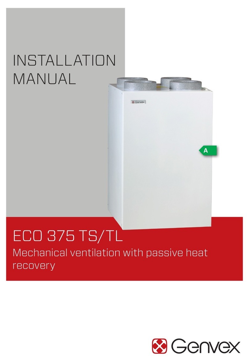
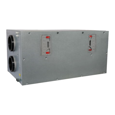
Genvex ECO 360 R User manual

INSTALLATION
MANUAL
ECO 360 R
Mechanical ventilation with passive heat
recovery
A

TABLE OF CONTENTS
Safety information..................................................................................................................................................................3
Functional description...........................................................................................................................................................4
Installation .................................................................................................................................................................................5
Wall mounting (vertical connections).....................................................................................................................5
Floor mounting (vertical connections)...................................................................................................................6
Dimensional sketch.......................................................................................................................................................7
Horizontal mounting of the unit (horizontal connections) .............................................................................7
Duct connection.............................................................................................................................................................8
Duct system..................................................................................................................................................................10
Insulation of ducts in cold attics...........................................................................................................................11
Insulation of ducts in heated rooms ....................................................................................................................11
Post-heating of supply air .......................................................................................................................................11
Electrical installation ................................................................................................................................................12
Control and commisioning of the system...........................................................................................................12
Optimal initial commisioning of the system......................................................................................................12
System maintenance...........................................................................................................................................................13
Filters..............................................................................................................................................................................13
Access to internal parts...........................................................................................................................................14
Cleaning and inspection of rotary heat exchanger.........................................................................................15
Post-heating surface.................................................................................................................................................16
Fan ...................................................................................................................................................................................16
Supply air and exhaust air valves .........................................................................................................................16
Recommended maintenance intervals ...............................................................................................................17
Spare parts..............................................................................................................................................................................18
Troubleshooting ....................................................................................................................................................................19
Safety thermostat in electric heating surface....................................................................................................
19
System not running.................................................................................................................................................. 19
No supply air ...............................................................................................................................................................19
No exhaust air.............................................................................................................................................................19
Cold supply air............................................................................................................................................................19
Alarms .......................................................................................................................................................................... 19
Electrical diagram Optima 270 – right..........................................................................................................................20
Electrical diagram Optima 270 – left ...........................................................................................................................21
Power consumption display, control and rotor..........................................................................................................22
Declaration of conformity.................................................................................................................................................23
De-installation instructions..............................................................................................................................................23

3
This manual also describes installation and service work to
be performed by a professional.
This appliance can be operated by children aged 8 and over,
by persons with reduced physical, sensory and mental
abilities, and by persons with a lack of experience and
knowledge, provided they are supervised or have received
guidance on using the appliance in a safe way and under-
stand the dangers involved. Children must not play with the
appliance. Cleaning and user maintenance must not be
performed by children without supervision.
Subject to design changes.
Labelling
The CE mark represents Genvex’s assurance that the
product complies with all regulations laid down for the
product in accordance with relevant EU directives. The CE
mark is mandatory for most products sold in the EU,
irrespective of where they are made.
SAFETY INFORMATION

4
FUNCTIONAL DESCRIPTION
The ECO 360 R is a ventilation system for comfort
ventilation of homes.
The unit is equipped with a high-efficiency rotary heat
exchanger which recovers both heat and moisture as
needed – and thus ensures low energy costs and an optimal
indoor climate with reduced risk of the home drying out in
winter.
Due to the properties of the rotary exchanger technology,
no condensation is discharged from the system, which
means condensate drainage is not necessary. Similarly, a
balanced air volume can be maintained during defrosting of
the rotary exchanger, as the speed of the rotor is fully
modulating and reduced to a level necessary for efficient
defrosting. During defrosting, an integrated modulating
electric reheater ensures that the supply air temperature is
maintained at an appropriate level.
The unit can be supplied with integrated flow sensors,
ensuring easy commissioning and a constant air volume in
all conditions (flow sensors are accessories and ordered
separately).
The ECO 360 R is designed for indoor installation, but – if
specific country requirements allow – it can also be used
outside the building envelope in areas protected from wind
and weather.
NOTE
When installing outside the building envelope, condensa-
tion may occur on the outside of the system under certain
conditions. To avoid condensation, it is recommended
removing the steel front so that hot, moist air cannot build
up under the front lid.

5
INSTALLATION
IMPORTANT!
The unit may only be used in connection with an electrical
installation executed properly with grounding. It must also
be ensured that the earth connection of the electrical
installation is matched to the earth plug of the unit.
These instructions must be followed. If the installation is
not executed in accordance with these instructions, KVM-
Genvex cannot be held liable for any further damage that is
unrelated to the Genvex unit.
KVM-Genvex A/S always recommends careful planning of
the installation space for your Genvex product in relation to
the location of living spaces. As this is a technical product
that contains fans and/or a heat pump, in rare cases, and in
combination with inappropriate installation conditions, it
may cause unsatisfactory noise or vibration nuisance. As a
general rule, it is always recommended installing the
technical system so that it is not located in the immediate
vicinity of a bedroom. Furthermore, when securing the
Genvex unit to the building structure, it is recommended
attaching it to a heavy structural component such as
concrete. It should also be ensured that no sound or vibra-
tions can be transmitted through materials in contact with
the technical system. If there is a risk of propagation of
noise and vibrations, further installation of vibration-
damping material and sound-damping of installation rooms
are recommended.
Wall mounting (vertical connections)
Before starting the installation of the ventilation unit
Make sure that the wall used to hold the ventilation unit is
built in such a way that it is able to support the weight of
the unit. In addition, the wall must be straight and plumb.
1. Before attaching the mounting bracket to the wall,
ensure that the bracket is in the correct position and
that the necessary space and service conditions are
available. Place the mounting bracket level and mark the
positions of all 4 screw holes.
2. Attach the bracket to the wall using screws in all 4
mounting holes.
3. Mount the ventilation unit by hanging it on the mounting
bracket. The recess on the back of the unit is intended
for this.
Once the ventilation unit has been properly attached to the
mounting bracket, lock the unit in place by inserting the
locking screw into the locking hole. The supplied safety
screws must be fully tightened!

6
Floor mounting (vertical connections)
1. The 4 supplied adjusting legs are screwed into the
threaded holes in the base of the unit.
2. The adjusting legs can be adjusted from 27-35 mm to
level the unit.
Horizontal mounting of the unit
(horizontal connections)
Note – for this installation method, the filter on the right
side must be attached to the filter frame (e.g. using elastic
straps as shown in the picture below) so that the filter is
held in place and ensures 100% filtration.
Please note that this type of installation of the unit will
require particular focus on servicing and accessibility.
1. The unit is mounted on its back on a vibration-damping
surface – with service access from above as shown in
Figure 3. C.
5,534
600
600
596,4
131 131
143,2
282
200Ø
160
Ø
34
12
Figure 1. Adjusting legs
Figure 2. Filter in frame with elastic straps
Figure 3. Installation methods – ECO 360 R
A. Wall-mounted
B. Floor-standing
C. Horizontal
A.
B.
C.

7
Dimensional sketch
In order to allow access for servicing and maintenance,
there must be a clearance of at least 600 mm in front of
the ECO 360 R
5,534
600
600
596,4
131 131
143,2
282
200Ø
160
Ø
34
12
Right-hand version
1. Discharge air
2. Extract air
3. Outdoor air
4. Supply air
Left-hand version
1. Supply air
2. Outdoor air
3. Extract air
4. Discharge air

8
Duct connection
At duct connectors, a yellow sticker has been affixed
indicating which ventilation ducts are to be connected to
the various connectors.
Note that the ECO 360 R is available in a right-hand version
(characterised by the reheater being located in the supply
air to the right of the unit) and a left-hand version (charac-
terised by the reheater being located in the supply air to
the left of the unit).
It is possible to convert a right-hand unit into a left-hand
unit and vice versa by relocating the humidity sensor +
exhaust sensor and post-heating surface. For more details
on conversion, contact your Genvex sales representative.
ECO 360 R Right-hand
ECO 360 R Left-hand
334,4
282143,2
160
200
334,4
282143,2
160
200

9
To start the duct installation, it is recommended using 4 x
Ø160 mm nipple connectors with double sealing lips.
Alternatively, a Ø200 mm spiro pipe can be used, which is
connected directly to the outside of the ECO 360 R
connector.

10
Duct system
It is recommended that the duct system should be made of
spiral-folded pipes assembled with fittings with rubber ring
seals so that you get a tight and durable duct system. To
achieve a satisfactorily low noise level from the unit, sound
locks must always be installed on the supply air and ex-
haust air duct system between the unit and the first supply
air and exhaust air fittings.
It is recommended that the air flows in the ducts should be
dimensioned at a sufficiently low level to ensure that noise
from the supply air and exhaust air fittings does not occur.
When positioning outdoor air and exhaust air hoods/
gratings, it must be ensured that the two air flows do not
short-circuit, thereby preventing the exhaust air from being
sucked in again. It is recommended that grates should be
placed on the north or east side of the house to achieve
optimal comfort in homes/flats.
It is recommended that the air intake should be located on
the north or east side of the house to achieve maximum
comfort and minimal impact from the sun’s heat.
Recommended minimum horizontal distance between air
intake and exhaust: 3 metres.
Recommended minimum vertical distance between air
intake and exhaust: 1 metre.
In order to connect ordinary galvanised steel ducts to the
ECO 360 R ventilation unit, you must first install 4 nipple
connectors in the unit’s Ø160 mm openings (double sealing
lips). Alternatively, Ø200 mm galvanised steel ducts should
be placed over the EPP connectors.
The unit is now ready for direct connection of ductwork on
the nipple connector. It is recommended installing galva-
nised angle brackets to fasten the nipple connector to the
galvanised housing using self-tapping steel screws.
3 m
1 m
3 m
Kanalisolering, alt. A Kanalisolering, alt. B
Forkert isolering

11
Insulation of ducts in cold attics
To benefit from the unit’s high recovery potential (efficien-
cy), the ducts must be correctly insulated.
Supply air and exhaust air ducts
In order to minimise heat loss from the duct system in cold
attics, supply air and exhaust air ducts must be provided
with at least 100 mm of insulation. If insulation from
alternative A is used, it is recommended executing with two
layers of 50 mm lamella mats with paper or foil externally
and with staggered joints between the two layers. If the
ducts are laid on the main beams of truss frames, alterna-
tive B can be used. The insulation must always be packed
tightly around the ducts.
Outdoor air and exhaust ducts in cold areas
It is recommended providing ducts for outdoor air and
exhaust ducts with at least 50 mm of insulation. The
outdoor air duct is insulated to prevent warm air in the
attic from heating the fresh air in the summer. Be sure to
seal the termination where the outgoing duct passes
through the roof or gable to prevent condensation damage.
Insulation of ducts in heated rooms
Genvex recommends the following:
Supply air and exhaust air ducts
In a warm attic, the supply air and exhaust air ducts must
be provided with 50 mm of insulation finished with alumini-
um foil. Supply air and exhaust air ducts routed through
heated rooms in the home do not need to be insulated
unless cooling, a bypass or a geothermal heat exchanger
are used. In this case, the supply air duct must be insulated.
Outdoor air and exhaust ducts
In warm attics and heated rooms in the home, outdoor air
and exhaust ducts must be provided with a minimum of 50
mm of insulation.
In addition, the insulation must be lined on the outside with
plastic or aluminium foil to prevent condensation in the
insulation.
Contact your local supplier for advice on the national
insulation guidelines.
When using a geothermal heat exchanger, it is recommend-
ed adding 100 mm of insulation to the outdoor air duct.
Reheating of supply air
As the rotary exchanger in the ECO 360 R cannot recapture
all the heat from the exhaust air to the supply air, in the
winter season the supply air will be colder than the room
temperature in the home.
Especially during periods of very cold outdoor tempera-
tures, and depending on the chosen frost protection
strategy, the speed of the rotary heat exchanger can be
reduced during defrosting and the supply air temperature
will subsequently drop briefly.
The built-in electric reheater will ensure that a suitable
supply air temperature is maintained in all conditions,
provided this function is activated via the controls.

12
Electrical installation
The ECO 360 R comes prepared for external connection of
a 230V appliance connector, internet and display, BMS
connection and Genvex accessories.
See wiring diagrams and operating instructions for the
Optima 270 for more information.
In general, all electrical connections to the ECO 360 R must
be executed by an authorised electrician.
Important!
For functional and safety reasons, the unit must be con-
nected to a socket with grounding matched to the plug
connection.
Control and commisioning of the system
To achieve optimal operation of the system, it must be
commisioned using specialist ventilation measuring
equipment. If it is desired to put the system into operation
before commisioning, the following approach can be taken:
Before putting the system into operation
1. Check that the Genvex unit is correctly mounted and that
all the ducts are properly insulated.
2. Check that the door can be opened so that it is possible
to service and maintain the unit.
3. Check that the filters are clean (they may be dirty after
installation).
4. Set all supply air valves so that the valve closest to the
unit is opened 3 turns from the closed position and the
outer one is opened 8 turns from the closed position. The
intermediate valves are opened between 4 and 7 turns,
depending on how close they are to the unit.
5. It is recommended setting the integrated post-heating
surface to a supply air temperature of 0-3° below the
room temperature in the home so that the post-heating
surface is only used to temper the supply air.
The system can now be put into operation and run until it
is commisioned using specialist ventilation measuring
equipment.
Optimal initial commisioning of the system
Genvex recommends that the ventilation unit should be
commisioned by an authorised Genvex dealer before it is
put into operation.
Before starting the initial commisioning, check that the 5
points in the section on control and commisioning of the
system have been performed. Then start the unit:
Set the initial basic ventilation value, which is speed 2. To
reduce energy consumption as much as possible, first
adjust the main air volumes to the desired levels by adjust-
ing the speed of the fans via the control panel.
Then adjust the supply air and exhaust air valves with air
measuring equipment (during the initial commisioning of
the valves, remember to lock them and to turn the baffle
plate in the supply air valves so that the air blows in the
right direction).
Then check the main air flows again and fine-tune them
using the outdoor air and exhaust air valves (remember to
lock the position of the valves after initial commisioning).

13
Remember to switch off the power by removing the appli-
ance connector from the ECO 360 R or at the socket (it can
be difficult to reach the appliance connector on the unit
when ducts have been mounted and insulated) before
changing the filter or opening the unit.
Filters
When the filter timer reaches the set value for a filter
change, this will appear in the text in the Optima Touch
display or in the Genvex app, or be indicated by a yellow
flashing light in Optima Basic. This means that the filters
must be replaced/cleaned.
The system is stopped by removing the appliance connec-
tor from the ECO 360 R or at the socket. The filter plugs
are opened and the filter drawer is pulled out. Once the
filters have been cleaned/replaced, insert the filter drawer
with the clean filters and click the filter plugs into place in
the cabinet again. Reconnect the 230V power.
The filter alarm can now be reset via the display or the app.
The system then returns to normal operation.
If you want to replace the filters with a different time
interval,this can be done via the user menu.
Do not vacuum or clean at high air pressure.
This will damage the filter!
SYSTEM MAINTENANCE

14
Access to internal parts
To access internal parts of the ECO 360 R, the front plate,
control board and rotary exchanger must be removed.
1. Remove the screws from the front plate to access
internal parts.
2. Remove the protective plate covering the control board.
3. Remove the 230V power cable and the control cable for
the rotary exchanger motor.
4. Remove the PCB holder by removing the mounting
screws.
5. Lift the control board and pull out the rotary exchanger.

15
Cleaning and inspection of rotary heat exchanger
Inspect the rotary exchanger for dirt and, if necessary, use
compressed air at low pressure (max. 8 bar) to blow the
lamellae free of dirt.
Check brush strips and synthetic leather seals around the
rotor for leaks. If seals show signs of leakage, these must
be replaced.
When replacing brushes, unscrew the strips as shown in the
picture below. New brushes are fitted and the strips
screwed back on. BE CAREFUL not to overtighten the
screws for the brush strips!
Check that the drive belt for the rotor is tight so that it
does not slip in the pulley wheel of the motor. Check that
the belt is intact and shows no signs of wear. Replace the
drive belt as needed.
The ECO 360 R is supplied with an extra drive belt fitted –
this can easily be mounted on the rotor motor by removing
the transport screw on the extra belt.

16
Supply air and exhaust valves
Clean the valves by wiping them with a dry cloth. Make sure
the valve does not rotate and thus cause a change in the air
volume.
Important!
When reinstalling the front plate on the ventilation unit, do
not use power tools to tighten the bolts, as this may result
in damage to the threaded connections. Carefully tighten
all the front-plate bolts until the front plate is firmly
seated on the housing of the ventilation unit.
Reheater
Inspect the reheater for dirt and make sure the plug
connections and heater are intact.
Fan
Check the two fans for dirt. If they are dirty, they can be
cleaned with a brush, bottle washer or similar.

17
Recommended maintenance intervals
Component Action Interval
Filter Replaced at regular intervals so that full efficien-
cy of the unit is achieved.
3–6 months
Fans Fans are cleaned to ensure operational reliability
and efficiency.
12 months
Rotary heat exchanger Make sure the lamellae are clean. Check the
condition of the drive belt and seals around the
rotor. Replace drive belt and seals/gaskets if
necessary.
12 months
Gaskets in general Check gaskets on the unit and make sure they are
intact
12 months
Supply air and exhaust valves Check for dirt in supply air and exhaust valves.
Clean as needed. Check that the valves have the
desired setting in relation to air volumes.
12 months
Air intake Check for dirt and grime in the air intake and
exhaust, and clean as needed.
12 months
Ventilation ducts Check the cleanliness of ducts and clean as
needed.
10 years
Brush strips and synthetic leather Check that the brush strips and synthetic leather
pack tightly around the rotor and that there is no
leakage. Replace brushes and leather if neces-
sary.
3 years

18
SPARE PARTS
No.Item no.Description
1 068098 Rubber foot Ø25x25, M6x18
2 069875 Optima 270 control board
3 069876 IO control board
4 071003 Complete fan housing
5 071007 Complete rotor
6 071035 Filter G4
7 071036 Filter F7
8 071056 Front cover white
9 071063 Reheater – EAH1000R
10 071066 Mounting brackets
11 071070 Complete door
No.Item no.Description
12 071008 Rotary exchanger Ø375x200
13 071009 Brush TF 4.8x14 4P BK 2TFBK
14 071010 Brush strip
15 071011 Vertical gasket – rotor
16 071012 Peripheral gasket – rotor
17 071017 Wire gasket, rotor cassette
18 071021 Drive belt Ø6
19 071022 24V motor
20 071023 Pulley wheel
21 071025 Converter 230V – 24V DC
22 071069 Vibration damper Ø20x10 M6
PARTS LIST
PART NUMBER
STOCK
NUMBER
ITEM
Gummifod Ø25x25, M6x18
068098
1
OPTIMA 270 Print
069875
2
IO print
069876
3
Samlet ventilatorhus
071003
4
Samlet Rotor
071007
5
Filter G4
071035
6
Filter F7
071036
7
Front cover hvid
071056
8
Eftervarmeflade - EAH1000R
0710639
Ophængningsbeslag
07106610
Samlet låge
071070
11
PARTS LIST - Rotor
PART NUMBER
STOCK
NUMBER
ITEM
Rotorveksler Ø375x200
07100812
Børste TF 4,8X14 4P BK 2TFBK
07100913
Børsteliste
071010
14
Vertikal pakning - Rotor
071011
15
Perifer pakning - Rotor
071012
16
Ledningspakning Rotorkasette
071017
17
Drivrem Ø6
07102118
24V motor07102219
Pulleyhjul
07102320
Converter 230V - 24V DC07102521
Vibrationsdæmper Ø20x10 M6
07106922
811 763
4
2
9
1
5
10
16
18 13 14
19
21
20 15
17
22
12

19
TROUBLESHOOTING
Safety thermostat in electric heating surface
If a fault occurs in the built-in electric heating surface, the
safety thermostat will switch off the unit. The electric
heating surface is equipped with a fire thermostat, which
automatically shuts off the power if the temperature
exceeds 40°C. When the temperature drops, the heating
surface automatically switches back on.
As an extra safety feature, there is a built-in thermal fuse
which triggers disconnection if the temperature exceeds
60°C.
Reconnection must be executed manually via the red button
indicated in the pictures below.
System not running
• Fuse in electric panel has blown, no voltage in the
system.
• One of the fuses in the system’s control board has blown.
• Loose wire, no voltage to the unit.
• Incorrectly set weekly program.
• Filter timer has switched off the system.
No supply air
• Defective supply air fan.
• Clogged supply air filter.
• Outdoor air grille clogged with dirt and leaves in the
autumn, or snow and ice in the winter.
• Fuse on control board has blown.
• Unit is defrosting (supply air fan runs at reduced speed)
• Incorrect setting of Optima controls
No exhaust air
• Defective exhaust fan.
• Clogged exhaust filter.
• Fuse on control board has blown.
Cold supply air
Fault
• Heat exchanger is clogged.
• Exhaust fan is defective.
• Exhaust filter is clogged.
• The electric post-heating surface has been switched off
at the overheating thermostat (only systems with
electric reheater installed).
• Air in heating pipe, defective thermostat/motor valve,
incorrect setting of control panel.
If none of the above errors are relevant, contact:
• During the warranty period (0-2 years), the installer from
whom the unit was purchased.
• After the warranty period (2 years ->), the installer from
whom the unit was purchased or the Genvex Customer
Centre by calling 7353 2700.
Please have the data from the type plate ready (silver plate
on the unit).
Alerts
See Optima 270 operating instructions.
No.Item no.Description
12 071008 Rotary exchanger Ø375x200
13 071009 Brush TF 4.8x14 4P BK 2TFBK
14 071010 Brush strip
15 071011 Vertical gasket – rotor
16 071012 Peripheral gasket – rotor
17 071017 Wire gasket, rotor cassette
18 071021 Drive belt Ø6
19 071022 24V motor
20 071023 Pulley wheel
21 071025 Converter 230V – 24V DC
22 071069 Vibration damper Ø20x10 M6
Left-hand system
Right-hand system

2020
ELECTRICAL DIAGRAM OPTIMA 270 – RIGHT
1
1
1
2
2
2 3
3
3
4
4
X1
X2
X3
X5
LED1 LED2
1
1
1
2
2
2 3
3
3
4
4
4321 4321
L4 L3 A L3 B L3 C L3 D L20 L21 L17 L18
H7H9
L17
L18
L3
L4
L1
L6
L8
L10
L11
L16L2
L22
F1 F3
H1
H3
H14
H17
H7
H9
X1
MODBUS
Master
MODBUS
Display
MODBUS
CTS
RUN
ERROR
LAN OK
RJ45
ES 2010 - Optima 270
USB-mini
L
L
L
L
L
L
L
N
N
N
N
N
N
GND
GND
GND
GND
GND
GND
GND
GND
Sensor
3,3V
GND
24VDC
24VDC
GND
GND
GND
GNDGND
24VDC24VDC
AA
BB
GND
GND
0-10V
0-10V
Tacho
Tacho
Signal
Signal
Signal
0-10V
Sensor
Sensor
Sensor
Sensor
Sensor
T8
T9
R1
R2
R3
R4
R5
CR2032
8A 2,5A
5x20mm5x20mm
NL
GND
+24V
123 123 1234 1234
Rotor Motor
+24V
GND
0-10V
L1
L6
L8
L10
L11
L16
GND
GND
GND
GND
24VDC
24VDC
GND
GND
GND
GND
24VDC
A
B
Signal
Signal
0-10V
Sensor
Sensor
T8
T9
4321 4321321 321
L
L
N
N
L2
GND
24VDC
A
B
1
12
2 3
34
1
12
2 3
34
X1
1
2
3
4
A
B
GND
+24VDC
Signal
GND
+24VDC
+24VDC
GND
Signal
Rh
JRS
16-02-2021
Version 1,1
X2
X3
A
B
GND
+24VDC
A
B
GND
24
23
22
21
1
2
3
4
L22
X5
Mains connection
1x230V 50Hz, L, N, PE
Max: 10A
Output H3 - Service menu - EC13
Preheat / Reheat / Always On
1x230V 50Hz
Max.load 1800W
Aux. relay H17
1x230V 50Hz
ONLY control current
Sensor T8 Frost
Sensor T7 Extract air
Sensor T4 Exhaust air
Sensor T3 Outdoor air
Sensor T1 Supply air
Sensor T9 Option
External stop
EC fan Extract air
Blue
Yellow EC fan Supply air
Blue
Yellow
EC fan Extract air
1x230V 50Hz
Blue
Yellow/green
Humidity sensor P1
EC fan Supply air
1x230V 50Hz
Control signal Rotor
Modulating Reheating
Modulating Preheating
Potential free input
for optional:
Humidistat,
Extractor hood
White
White
Modbus Master /
ES1048
Blue
Yellow/green
Yellow/green
Yellow/green
Brown
Blue
Brown
Blue
Flow sensor Extract air
Flow sensor Supply air
Optima Touch Display /
Optima Basic Display
Optima Touch Display /
Optima Basic Display
Modbus Master /
ES1048
Modbus CTS
Brown
Blue
Green / Blue
White / Yellow
Brown / Red
LED 1
On = Internet connection
LED 2
1 flash = External stop
2 flashes = Sensor error
3 flashes = Humidity sensor error
4 flashes = Fan error
5 flashes = Sensor Frost error
6 flashes = Fire failure / test
7 flashes = Fire failure - Damper 1
8 flashes = Fire failure - Damper 2
9 flashes = Fire failure - Box 1
10 flashes = Fire failure - Damper 3
11 flashes = Fire failure - Damper 4
12 flashes = Fire failure - Box 2
13 flashes = Rotor alarm
I/O PCB
Please ensure sufficient
earthing of the installation
Service menu EC 10 = Right
Yellow/green
Yellow/green
Blue
Blue
Blue
Blue
Brown
Brown
Brown
Brown
I/O PCB
Brown
Brown
Brown
Brown
Brown
Brown
White
White
White
White
White
White
White
White
White
White
White
Yellow/green
Yellow/green
Blue
Blue
Yellow
Yellow
Green
Green
Blue
Blue
Red
Red
Green
Green
Brown
Brown
Red
Red
Red
Black
Black
Table of contents
Other Genvex Fan manuals

Genvex
Genvex ECO 190 CS/CL User manual

Genvex
Genvex ECO 375 TS User manual

Genvex
Genvex ECO 375 User manual

Genvex
Genvex ECO 190 XL User manual

Genvex
Genvex ECO 400 XL User manual

Genvex
Genvex ECO 300 User manual

Genvex
Genvex ECO 275 User manual

Genvex
Genvex GE ENERGY 3 User manual

Genvex
Genvex OPTIMA 270 User manual