Geonav 6 Sunshine Manual

offered by Busse-Yachtshop.com
User and Installation Guide
6SUNSHINE

offered by Busse-Yachtshop.com
User and Installation Guide
6SUNSHINE

offered by Busse-Yachtshop.com
READ THIS WARNING BEFORE USING THE GEONAV
WARNING
THE ELECTRONIC CHART IS AN AID TO NAVIGATION
DESIGNED TO FACILITATE THE USE OF AUTHORIZED
GOVERNMENT CHARTS, NOT TO REPLACE THEM.
ONLYOFFICIALGOVERNMENTCHARTSANDNOTICES
TO MARINERS CONTAIN ALL INFORMATION NEEDED
FOR THE SAFETY OF NAVIGATION AND, AS ALWAYS,
THE CAPTAIN IS RESPONSIBLE FOR THEIR PROPER
USE.
The use of the GEONAV implies knowledge and accep-
tance of this warning by the user.
NOTE: The technical characteristics and functions described in this manual are
subject to change as a result of improvements or changes to the product.

offered by Busse-Yachtshop.com
45
EnglishEnglish
CHARACTERISTICS
General characteristics
• Compact chart plotter with optional built-in GPS receiver
and antenna
• 12-channel internal GPS (optional)
• Satellite acquisition time:
2 minutes (cold)
15 minutes first fix (with internal GPS)
• GOTO function (Port, Nearest Service, Marker, Lat/Lon)
• External GPS interface via NMEA 0183
• Depth sounder interface via NMEA 0183
• Display of depth and water temperature data (if interfaced
with an echosounder)
• Autopilot interface via NMEA 0183
• Chart Rotation (head-up display)
• Screen Amplifier™ function
• Autozoom™ function
• Overzoom™ function
• 8 marker shapes, 8-character name
• Reverse route function
• Selectable depth units (meters, feet and fathoms)
• Cartography with port services and Tides and Currents
data
• 16 zoom levels
• Heading vector
• CompactFlash™ cartridge
• Storage of routes, tracks and markers in separate files on
CompactFlash™ cartridges
• Built-in world map
• Splash-proof
• Weight: 1 kg
Electrical characteristics
• Input voltage: 9.8VDC to 18 VDC with protection against
reverse polarity and overvoltage
• Power consumption: 10 W
INTRODUCTION
The GEONAV is a chart plotter that displays your boat’s cur-
rent position with respect to an electronic chart.
The unit can be optionally equipped with a built-in GPS re-
ceiver that can track up to 12 satellites simultaneously and be
interfaced with:
• An external GPS
• A depth sounder
• An autopilot
By using a GEONAV and a NAVIONICS electronic chart, you will
never get lost even in bad weather conditions such as fog, rain or
dark because your plotter will always display where you are and
where your are heading to.
The ROUTE function will allow you to plan a trip, MARKERS will
allow you to mark points of interest whereas the TRACK function
will allow you to record your actual route. Thanks to the un-
limited capacity of the new CompactFlash™ cartridges - that
can also be used on PCs as personal hard disks - the instru-
ment can store a large amount of route, track and marker data.
NAVIONICS GOLD CHARTS are available for all the most popu-
lar boating areas and can be used in addition to official paper
charts to obtain additional information, such as the availabil-
ity of port services, as well as tides and currents data.
NAVIONICS electronic charts are available worldwide from
authorized NAVIONICS dealers.
Should new functions be available in the future, it will be
possible to update the GEONAV internal software at any
NAVIONICS dealer.
Introduction Characteristics
GPS inside
model

offered by Busse-Yachtshop.com
67
EnglishEnglish
• Operating temperature: 0° to +60° C, humidity 93%
• Storage temperature: -20°C to +70°C, humidity 93%
• Color LCD, TFT 5.6”, sunlight visible
• Adjustable backlight and contrast
• Backlight keypad
• Pixel resolution: 240 x 320
• 32-bit RISC processor
Memory characteristics
• Up to 20 waypoints per route
• Up to 500 trackpoints
• Up to 99 markers per group
• Number of routes, tracks and markers: unlimited, depend-
ing on the size of the CompactFlash™ used
Interface characteristics
• Standard NMEA 0183 sentences
- from the position sensor:
GLL, VTG, GGA, RMC, GSV, ZDA, RMA, GSA
- from the depth sounder:
DBT, MTW
- to the autopilot:
APA, APB, XTE, RMB, BWC, GLL, VTG
If received from the GPS, the following sentences are trans-
mitted:
GGA, RMC, ZDA
Accessories
• Bracket for fixed installation
• Gasket and drilling template for panel mounting
• Data cable for connection to external GPS, depth sounder
and autopilot
• User’s manual
• Carrying case
Characteristics

offered by Busse-Yachtshop.com
89
EnglishEnglish
•Autopilot: To connect the GEONAV to an autopilot, use the
data cable provided with the unit (see the Connections Sec-
tion).
•Depth sounder: To connect the GEONAV to a depth sounder, use
the data cable provided with the unit (see the Connections Sec-
tion).
Fixed mounting
The plotter can be mounted
on any surface using the
mounting bracket provided
with the unit (see figure).
Use 4 flat-head screws (5mm)
to fix the bracket to the de-
sired mounting surface.
Since the bracket does not
allow any left or right rota-
tion, make sure that the unit
is properly installed for the
best view angle.
Panel mounting
Locate the area where the GEONAV is to be installed, then
use the drilling template supplied with the plotter to properly
cut holes and sockets out of the instrument’s panel.
The neoprene adhesive gasket supplied must be applied to the
GEONAV rear side to avoid moisture penetration and to re-
duce vibrations.
Mounting screws must be 4 mm in diameter and maximum 5
mm in length, plus the thickness of the panel. Do not exceed
tightening the screws, in order to avoid damaging the screw
seats.
INSTALLATION AND PRECAUTIONS
To avoid electromagnetic interference, the GEONAV must be
positioned at least 0.35 meters away from magnetic compasses
or flux-gate sensors, such as those used on autopilots and
remote electronic compasses.
The GEONAV is water resistant, but not waterproof. It is es-
sential that the rubber cover on the right side of the unit is
firmly inserted into the cartridge slot; the rubber cover should
be removed only when the CompactFlash™ has to be inserted
or replaced and, in this case, the unit must be perfectly dry.
NOTE: Any damage caused by the presence of water inside the cartridge slot, due
to the cover missing or incorrectly replaced, is specifically excluded from the war-
ranty.
Cleaning
It is recommended that you use a non-alcoholic product to clean
the glass, since alcoholic products may damage the glass surface
or make it opaque.
Installation
The GEONAV allows using either the built-in antenna for outdoor
installation or an external GPS antenna for indoor use.
NOTE: At start-up, the plotter will select the internal GPS by default.
•Internal GPS (if available):For the best reception of satellites,
mount your unit in an open area to allow the built-in an-
tenna to have the best sky visibility. If the instrument is
installed so as to allow full horizon visibility, the best per-
formance will be ensured.
•External GPS:Instead of a built-in antenna, you can use an
external GPS. To connect the GEONAV to an external an-
tenna, use the data cable provided with the unit (see the
Connections Section).
Installation and Precautions

offered by Busse-Yachtshop.com
10 11
EnglishEnglish
CARTRIDGE INSTALLATION
Installing the CompactFlash™
Remove the rubber cap from the cartridge slot located in the
right-hand side of the plotter.
Insert the cartridge into the appropriate slot, with the label
side (side with a small arrow) backwards and push it.
Replace the cap exercising firm pressure and check that it is
perfectly closed, in order to avoid any water infiltration.
NOTE: Make sure of inserting the cartridge correctly. Should you try to insert the
wrong side of the cartridge, full insertion into the slot is hampered. Any further attempt
to force the cartridge into the slot may damage the cartridge or the plotter. This kind of
damage is not covered by the warranty.
Removing the CompactFlash™
Make sure that the plotter is perfectly dry.
Remove the rubber cap from the cartridge slot located in the
right-hand side of the plotter, then extract the cartridge.
Cartridge Installation
CONNECTIONS
Power supply and data cable
1. Power supply
red wire +VDC pin 1
black wire GND pin 2
2. Data input ext. GPS
brown wire ext. GPS in + pin 3
yellow wire ext. GPS in - pin 4
3. Data output
violet wire Autopilot out + pin 5
white wire Autopilot out - pin 6
4. Data input depth sounder
blue wire DS in + pin 7
green wire DS in - pin 8
SHIELD pin 9
If sent by the autopilot, the following NMEA messages are
transmitted to external devices: GGA - RMC - ZDA
The GEONAV will add the following messages: APA - APB -
XTE - RMB - BWC - GLL - VTG
The data cable is supplied together with the GEONAV plotter.
WARNING: Once the installation is completed, always make sure that all wires are
properly connected since wrong connections may damage the unit.
Connections

offered by Busse-Yachtshop.com
12 13
EnglishEnglish
• Cursor mode:
Deletes the last
waypoint or the
marker pointed by the
cursor.
CURSOR
• Moves the manual
cursor across the
screen.
• Allows switching from
Navigation mode to
Cursor mode.
• Allows selecting from
the options in the
menu /submenu.
• At start-up, allows
adjusting the screen
contrast.
PWR
• Switches the GEONAV
on / off.
• Allows adjusting the
screen backlight.
• Allows adjusting the
screen contrast.
KEYBOARD
ZOOM+/ZOOM-
Selects the chart range.
ENTER
Enters a waypoint or a
marker, or confirms a
selection from the menu.
PAGE
• Navigation mode:
Turns navigation data
pages.
• Cursor mode:
Allows switching from
Cursor mode to Navi-
gation mode.
GOTO
Allows plotting a route to-
ward a manual cursor
position, desired marker,
port, nearest port service
or specified position (lat/
lon).
CLR
• Navigation mode:
Deletes the current
route.
Keyboard
Cartridge Installation
WARNING: The rubber cover should be removed only when inserting or replacing
the cartridge.
WARNING: Always use CompactFlash™ cartridges certified by Navionics. The
use of non-certified cartridges may result in improper operation of the unit.
The CompactFlash™ cartridges can be used as a mass-storage
with any PC computer, so can be the cartridge used by the
plotter. However, the plotter needs to find some free space in
the cartridge in order to work properly. Prior to use a new
cartridge, always make sure that there are at least 2.5MB of
free space.
WARNING: Be careful when handling the cartridge files by using the PC. Windows
allows deleting and moving files easily, therefore pay attention when using Windows
Explorer not to erase the content of the \NAVIONIC and \GEONAV folders. Damaging
the files stored in such directories may result in loss of data or improper operation of
the unit.

offered by Busse-Yachtshop.com
14 15
EnglishEnglish
NAVIONICS ELECTRONIC CHARTS
The GEONAV includes a built-in world map that allows zoom-
ing from 4,096 down to 512NM. Additional cartography de-
tails relative to a specific area of navigation are available from
the CompactFlash™ cartridges storing NAVIONICS GOLD
CHARTS.
To display chart boundaries, press PAGE until the menu bar
appears, select SETUP, CHART BOUNDARIES, then select
ON/OFF to enable/disable the boundaries of the charts stored
in the cartridge. A small square will locate the area covered by
the cartridge installed.
Increasing/decreasing the chart range
Press the -ZOOM+ key.
Displaying depth and safety contours,
geographical names, spot soundings
and light sectors
Press PAGE to display the menu,
select SETUP and enable the
option desired (Depth Cont.,
Safety Cont., Spot Soundings,
Names or Light Sectors) by us-
ing the CURSOR key.
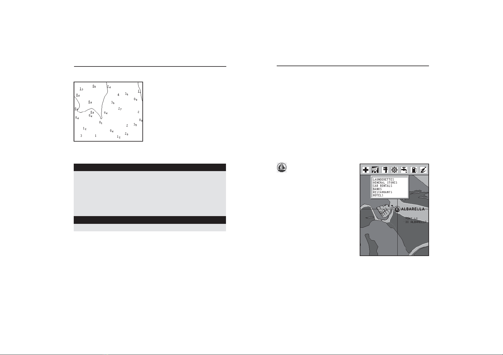
Converting depth values into the units
set
Press PAGE to display the menu,
select SETUP, DEPTH UNITS
and then set the unit desired to
meters, feet or fathoms.
The GEONAV will convert all the depth values in the unit
selected, making them appear like those reported in the offi-
cial nautical charts (see the figure).
NAVIONICS Electronic Charts
Diagnostic
DIAGNOSTIC
The GEONAV features a diagnostic program to verify its cor-
rect performance, once installed, and to detect problems that
may occur during the use of the unit.
To access the diagnostic program, keep pressed any key but
CLR, while pressing the PWR key.
The GEONAV will switch on and carry out automatically a
test of the whole system; as soon as the memory test is com-
pleted, the program will test the LCD, the CompactFlash™
card and the keyboard. Press ENTER to run one test, CLR to skip
to the next one. To exit from the keyboard test, press CLR
twice.
Once the keyboard test is completed, the diagnostic program
allows checking the messages received from the GPS through
the NMEA 0183 port. Hold the ENTER key pressed to freeze the
messages on the screen, then release it to keep on displaying
the new messages sent by the GPS. To test channel 2 (depth
sounder or wind instrument), press GOTO. Press CLR to quit.
After the keyboard, the diagnostic program will test the inter-
nal GPS (if available) and the backlight. Press ENTER to run
one test, CLR to skip to the next one.
Once terminated all tests, press ENTER to re-boot the unit.
WARNING: The internal memory can be cleared by pressing simultaneously the
PWR and CLR keys. This operation will delete all the settings stored in the GEONAV
and restore factory settings.
NOTE: In case of damaged cartridge or abnormal power spikes, the unit might lock,
requiring a power shutdown to restart. In that case, the unit can be turned off without
the need of detaching the power, by simply pressing the GOTO, PAGE and CLEAR
keys at the same time. This function is useful if the unit is panel mounted or flush
mounted and the power switch cannot be easily accessed.

offered by Busse-Yachtshop.com
16 17
EnglishEnglish
Changing chart symbols
The symbols used to represent the objects on the chart (buoys,
lights, landmarks, etc.), as well as chart colors, can be se-
lected between paper-chart International or US styles.
Press PAGE to display the menu, select SETUP, then move the
cursor to the next page and select PRESENTATION (INTER. or
US).
Displaying port services
NOTE: This function is available only with the NAVIONICS cartridges containing the
Port Services feature.
This symbol identifies a
port providing services.
Zoom down to 1 NM, position the
manual cursor on the icon (sail-
ing boat) relative to the selected
marina.
By pressing ENTER, a window
will list all the services available
in that port.
Select the desired icon by using
the CURSOR key.
Port services are identified by the
icons shown in the table on the
following page.
The number and the type of service available will depend on
the NAVIONICS cartridge installed.
ABBREVIATIONS FOR LIGHT ABBREVIATIONS FOR COLOUR
AL alternating AM amber
F fixed B black
FLL fixed and flashing BL blue
FL (...) group flashing G green
FL single flashing OR orange
IQ interrupted quick R red
OC single-occulting VL violet
OC (...) composite group occulting W white
Q continuous group Y yellow
ABBREVIATION FOR PERIOD ABBREVIATION FOR RANGE
..S xx seconds ..M xx nautical miles
Displaying abbreviated navaid charac-
teristics
Position the manual cursor on
the navaid symbol.
A window will show the abbre-
viated characteristics relative to
the navaid selected.
Description of abbreviated navaid characteristics:
Displaying object attributes
Move the manual cursor on top of an object on the chart, then
press GOTO and select INFO. A window will show the descrip-
tion of all the objects present on the chart at the cursor posi-
tion. Select one object from this window and press ENTER to
show all of the object attributes.
The objects that can be queried include depth contours, depth
areas, point objects (lights, navaids, landmarks, etc.), land
areas, spot soundings, coastlines, rocks, wrecks and in gen-
eral any symbol present on the chart.
NAVIONICS Electronic Charts

offered by Busse-Yachtshop.com
18 19
EnglishEnglish
GRAPHIC ITEMS
Besides chart data, the GEONAV displays some graphic items use-
ful during navigation.
The figure below shows some of these items.
1 - Marker
Indicates a point of interest associated with a symbol and a name.
2 - Track segment
Recording of the track actually followed by the boat; the track is
displayed as a dashed line.
3 - Boat’s position
Boat’s position according to the data received from the GPS re-
ceiver.
4 - Rubber band
Line joining the last waypoint entered to the manual cursor, or the
boat’s position to the manual cursor when no waypoint has been
entered.
Graphic Items
Displaying Tides and Currents data
NOTE: This function is available only with the NAVIONICS cartridges containing
Tides and Currents data.
Position the cursor on the icon of a Tide or Cur-
rent station, then press ENTER.
A graph will show the tide rate or the tidal stream relevant to
the station selected, as measured during the current day.
NAVIONICS Electronic Charts
Healthandfirstaid
services
Touristservicesand
shops
Engine,boat,
electronicand
otherrepairs
Information
andport
authorities
Tidestation
Currentstation
Customerservices
Water
Fuel

offered by Busse-Yachtshop.com
20 21
EnglishEnglish
FUNCTIONAL CHARACTERISTICS
This chapter describes some of the most important functions
of the GEONAV, as well as the terms most commonly used in
this document.
Switching on/Switching off the unit
To switch the GEONAV on, press the PWR key. To switch it
off, keep the PWR key pressed for more than 3 seconds.
Internal or external GPS
To make the installation easy, the GEONAV can use either its
own internal GPS receiver (if available) or an external receiver,
depending on where the unit is to be installed (indoor or out-
door).
To select the internal/external GPS, press PAGE to display the menu,
select SETUP, then GPS INT or GPS EXT.
Depth sounder
When in depth sounder mode, the GEONAV displays the naviga-
tion window in the screen upper part, and, in the bottom part, the
sea depth in graphic form.
The depth value can be expressed in meters (selected by default),
feet and fathoms; press PAGE to display the menu, select SETUP
and then DEPTH UNITS (M/FT/FA).
Navigation mode (Automatic)
The GEONAV enters the Navigation mode as soon as the internal
or external GPS receiver transmits a valid fix; when in Navigation
mode:
• The manual cursor is not displayed
• The depth sounder window can be accessed
This mode is also called automatic because the unit automati-
cally selects the chart scale and updates the boat’s position on
the screen.
Functional Characteristics
GPS inside
model
To delete this band, press the PAGE key and switch to Naviga-
tion mode.
5 - Route leg
Part of route between two waypoints.
6 - Waypoint
Waypoints are identified by a circle and a number. The route start-
ing point is marked by the “X” symbol. The target waypoint is iden-
tified by a filled circle, whereas the route leg currently followed is
identified by a thicker line.
7 - Cursor
Indicates the position expressed in geographical coordinates (lati-
tude and longitude).
It is displayed when the plotter is in Cursor mode.
8 - Heading vector
Indicates graphically the boat’s current route.
9 – North indicator
Indicates the north direction when the Chart Rotation func-
tion is enabled.
Graphic Items

offered by Busse-Yachtshop.com
22 23
EnglishEnglish
Functional Characteristics
cally the boat’s position and the target waypoint at the best
available chart range. As the boat
approaches the target waypoint,
the unit will automatically zoom
in. Once the waypoint is passed,
the unit will select the best range
to display the boat’s position and
the following waypoint.
To activate the Autozoom function, press ZOOM+ until the
“AUTOZOOM ? ENTER = YES” message is displayed.
To deactivate the Autozoom function, press the ZOOM key once.
When the GEONAV is turned on, and if at least one waypoint
has been previously entered, the Autozoom function is auto-
matically activated.
Screen Amplifier
This function automatically redraws the chart according to
the boat’s course, to maintain 2/3rds of the screen ahead of
the boat, provided that the boat’s
speed is greater than 3 knots.
This function will be activated
only if no waypoint has been
previously inserted.
Overzoom
The Overzoom function allows
the chart scale to expand any-
where up to 1/4 NM. The
Overzoom does not provide any
additional chart detail, but im-
proves only the readability of the
existing information, thus act-
ing as a magnifying glass.
When the Overzoom is activated,
the unit will warn the user by
Cursor mode (Manual)
When in Cursor mode, the manual cursor is displayed. It is
possible to edit a route, insert or delete markers, display navaid
information etc., but it is not possible to gain access to the
depth sounder window. By pressing one of the four arrows in
the CURSOR key, the unit switches from Navigation to Cursor
mode, and the screen is centered in relation to the manual
cursor. To return to Navigation mode press PAGE.
Chart rotation
Charts are traditionally displayed in
north-up mode. This, however, does not
correspond to reality. For example,
when traveling southwards, the chart
shows, on the right side of the boat,
what is actually located on the left side,
and vice versa.
The Chart Rotation function allows ro-
tating the electronic chart displayed ac-
cording to the plotted route (COG -
Course Over Ground) as detected by the
GPS receiver. Since the COG value var-
ies continuously, a filter has been in-
serted to prevent the chart from bounc-
ing.
To activate the Chart Rotation function,
press PAGE to display the menu, select
SETUP, then CHART ROTATION and
ON. A message will prompt the user to
select the requested maximum range be-
fore activating the chart rotation.
The northern direction will be indi-
cated by the symbol .
Autozoom
With the Autozoom function the
GEONAV will always display automati-
Without rotation
With rotation
Without screen amplifier
With screen amplifier

offered by Busse-Yachtshop.com
24 25
EnglishEnglish
Functional Characteristics
To cancel local time, press PAGE until the menu bar is dis-
played, select SETUP, SET TIME and then GMT.
Chart presentation
This function allows the user to select the symbols and colors
of chart presentation between International mode and US mode.
To change the chart presentation mode, press PAGE to display
the menu, select SETUP, PRESENTATION and then choose
the option desired.
Display mode
The chart color can be selected among three predefined modes:
BRIGHT (bright light), DAY (normal light) and NIGHT (poor
light).
Press PAGE to display the menu, select SETUP, MODE and
then choose the option desired.
Depth contours
This function allows the user to select the display of depth
contours; the options available are:
OFF: no depth contour displayed
5m: display of contours only with depths up to 5 meters
10m: display of contours only with depths up to 10 meters
20m: display of contours only with depths up to 20 meters
ALL: all depth contours are displayed
Safety contours
This function allows the user to display the depth areas cor-
responding to the safety contour desired. The options avail-
able are:
OFF: no depth area displayed
2m: areas with depths up to 2 meters in dark blue
5m: areas with depths up to 2 meters in dark blue, up to 5
meters in blue
10m: areas with depths up to 5 meters in dark blue, up to
10 meters in blue
replacing RANGE with OVZ (blinking) within the navigation
window.
To activate/deactivate the Overzoom function, press PAGE un-
til the menu bar is displayed, then select SETUP, OVERZOOM
and ON/OFF.
Position calibration
Most position sensors have intrinsic errors that make the boat’s
position incorrect (from few meters to several hundred meters)
with respect to the background display of the chart.
This error is caused by the principle at the root of the satel-
lite-derived position system.
The position calibration allows the user to manually correct
the position error present in all GPS. Press PAGE until the
menu bar is displayed, select SETUP, CALIBRATION and then
ON.
A message will prompt the user to move the cursor to the boat’s
true position by using the CURSOR key. Press ENTER to move
the GPS boat’s position to the point indicated by the cursor.
This operation will save the calibration for use in future cal-
culations.
NOTE: When the calibration is activated, the coordinates will be marked by (*).
To cancel calibration, press PAGE until the menu bar is dis-
played, select SETUP, CALIBRATION and then OFF.
Local time
By this function the user can enter local time instead of the
Greenwich time (GMT) supplied by the GPS receiver.
To enter local time, press PAGE until the menu bar is dis-
played, select SETUP, SET TIME and then LOCAL.
A window will allow entering local time by using the CURSOR
key. Press ENTER to confirm the operation.

offered by Busse-Yachtshop.com
26 27
EnglishEnglish
GETTINGSTARTED
We recommend that you use the GEONAV intuitively, since
no damage will be caused by pressing an incorrect button.
Make sure that the unit is powered,
insert a CompactFlash™ cartridge and
then press PWR. At start-up, the last
chart used will be loaded by default. If
the chart is not found, the list of
NAVIONICS charts stored into the
CompactFlash™ cartridge will be dis-
played. Select the desired chart by the
CURSOR key, then confirm by pressing
ENTER.
A message will warn the user that electronic nautical charts
do not replace official government charts.
Press the PWR key to turn the display backlight on and adjust
brightness by the CURSOR key; press PAGE to continue.
The Satellite window will show the configuration of the sat-
ellites in use.
As soon as the GPS receiver has obtained a valid fix (it can
take a few minutes), the boat’s position and the relevant area
will be displayed at the best scale available.
The default language is English. To change the language, press
PAGE to display the menu, then select SETUP, LANGUAGE
and the desired language by the CURSOR key.
The line, or vector, starting from the boat indicates the boat’s
direction, to be ignored if the boat is stationary.
The window situated in the lower part of the screen will
display the boat’s speed, route and chart scale.
The GEONAV is in Navigation mode; by pressing the CURSOR
Getting Started
20m: areas with depths up to 10 meters in dark blue, up to
20 meters in blue
The areas whose depths are over the limit set, and therefore
navigable under safety conditions, will be displayed in white.
Dryline areas are always displayed in green.
NOTE: The mentioned colors are those used in the DAY mode. In NIGHT mode, the
areas with depths over the limit set, and therefore navigable under safety conditions,
are in black, whereas the colors below the limit are dark blue for higher depths and
blue for lower depths (e.g., 5m: areas with depths up to 2m displayed in blue, up to
5m in dark blue).
Chart loading
At start-up, the list of the NAVIONICS electronic charts stored
in the cartridge is shown, provided that a CompactFlash™
cartridge has been inserted.
Select the chart desired by CURSOR, then confirm by ENTER.
Each time the unit is switched on, the latest chart used will
be loaded.
To load another chart stored in the CompactFlash™. press
PAGE to display the menu, select SETUP and then SELECT
CHART.
Contrast/Brightness
Press the PWR key to display the CONTRAST/LIGHT win-
dow. To switch from one option to the other and to adjust the
contrast/brightness level, press CURSOR. Press the PAGE key
to exit.
The contrast can be adjusted at start-up, when the WARNING
message appears or when the satellite window is displayed;
press the ZOOM key and adjust the contrast.
Functional Characteristics

offered by Busse-Yachtshop.com
28 29
EnglishEnglish
NOTE: The cursor can be moved to the desired position by using the GOTO function
as well. See the GOTO Section for more details.
Getting Started
key, it is possible to switch to
Cursor mode (editing mode). The
cursor geographical position is
shown by two windows.
To plot a route starting from the
boat’s position, move the cursor
to the position desired, and press
ENTER to insert a waypoint at the
cursor’s position, that will be in-
dicated by a circle containing the
number 1.
The windows will show dis-
tance, bearing and the time to
reach the target waypoint.
Press the PAGE key to go back to
Navigation mode.
To add more waypoints, press
CURSOR and repeat the operations
described above.
As new waypoints are added, the
numbering will increase progres-
sively. In case of error, waypoints
can be deleted by pressing the CLR
key (Cursor mode), starting from
the last entered. To go back to
Navigation mode, press PAGE.
If an autopilot is connected to the
GEONAV, the plotted route is au-
tomatically followed as soon as the
Navigation mode is enabled.

offered by Busse-Yachtshop.com
30 31
EnglishEnglish
Satellite Window
SATELLITE WINDOW
NOTE: If a NAVIONICS cartridge with the Tides and Currents feature has been
inserted, the Satellite window will disappear as soon as a valid fix is obtained and be
replaced by the Info window.
At start-up the satellite window
displays how many and which
satellites are tracked by the GPS
receiver.
The outer circle represents the
horizon, the inner one identifies
a 45° elevation with respect to
the horizon, and the central
circle points to the zenith.
The small squares with numbers
show the satellites available.
As soon as a satellite is tracked
by the GPS receiver, the square
turns red. The bars displayed on
the left identify the signal qual-
ity; the longer the bar, the higher
the signal quality.
On the left of each bar, two digits indicate numerically the
signal/noise ratio.
Additional information:
•Day, month, year, local or Greenwich time (at the first
start-up the GEONAV is initialized to Greenwich Time).
•Boat’s position (lat/lon) (or the latest valid fix if the GPS
receiver is still searching for satellites).
•Data on the current satellite situation (number and fix).
•SOG, COG and altitude.
Operating Modes
OPERATING MODES
The GEONAV can operate in two different modes, Cursor and
Navigation, each giving access to different functions.
CURSOR MODE
When the GEONAV is in Cursor mode, the crosshair cursor is
displayed. The CURSOR key allow browsing through the elec-
tronic chart, as well as editing or creating the route. See the
Route Section for more details.
To enter the Cursor mode, press the CURSOR key.
NAVIGATION MODE
In Navigation mode, the boat’s position icon replaces the
crosshair cursor and several data windows can be accessed.
To enter the Navigation mode, press the PAGE key repeatedly.
As the fix is valid, the windows sequence is the following:
SATELLITE > NAVIGATION > MENU > DEPTH SOUNDER > TRIP >
INFO
The Depth Sounder window is displayed provided that data
is received from a depth sounder.
The Info window is displayed provided that a NAVIONICS
cartridge featuring Tides and Currents data is active (see the
Info Window Section).

offered by Busse-Yachtshop.com
32 33
EnglishEnglish
NAVIGATION WINDOW
This window is activated automatically as soon as the GPS
receiver has obtained the boat’s position (FIX OK).
If no route is present, speed, course and chart range are dis-
played at the bottom of the screen.
By using the ZOOM key, the chart detail level can be increased,
thus accessing NAVIONICS chart data.
If a route has been inserted, the screen will display the fol-
lowing data:
• Boat’s speed
• Distance from the target
waypoint
• Time to arrive to the target
waypoint
• Chart range
Navigation Window
The latitude and longitude values relevant to the boat’s posi-
tion are displayed as soon as three satellites are tracked and a
2D fix (two dimensions) is available.
The altitude value is available only if four satellites are tracked
and a 3D fix is obtained.
As soon as a valid fix is available, the GEONAV will automati-
cally switch to Navigation mode and display the boat’s posi-
tion at the best chart range available; the window at the bot-
tom of the screen will indicate the boat’s course and speed.
Satellite Window

offered by Busse-Yachtshop.com
34 35
EnglishEnglish
DEPTH SOUNDER WINDOW
A depth sensor can be interfaced with the GEONAV via NMEA.
In this case, the GEONAV auto-
matically enables the depth
sounder function, displaying a
graph of sea depth.
The depth scale, whose unit can
be selected from the menu in
meters, feet or fathoms, will
change automatically to show
deeper or shallower water.
In Navigation mode, press PAGE
until the depth sounder window
appears.
The window will display the fol-
lowing data:
• Water depth
• Depth scale
• Water temperature (if available)
When navigating in waters deeper than sounder access range or if
the boat’s speed is too high for depth sounding, data acquisition
will be interrupted and the number replaced by “—”.
To deactivate the depth sounder window, press PAGE.
Depth Sounder Window
MENU
The menu bar, displayed at the top of the screen, allows selecting
from the following options:
TRACK: To activate/deactivate the track function and to delete a
track saved.
ROUTE: To delete, reverse, store, recall a route and display
route information.
MARK: To delete, store and recall markers.
SETUP: To activate/deactivate the plotter’s setup.
Menu

offered by Busse-Yachtshop.com
36 37
EnglishEnglish
TRIP WINDOW
The trip window shows the data
relating to the route followed and,
in particular:
• Average speed
• Time elapsed from departure
• Partial distance covered
• Total distance covered
To reset partial counters before
starting a new journey, press
CLR.
Trip Window
Info Window
INFO WINDOW
When a NAVIONICS cartridge featuring Tides and Currents
data is present, this window displays further information,
besides the forecast data supplied by selecting the Tides and
Currents station.
The following data is displayed:
•Latitude and longitude at the
current boat’s position
•Current time and date
•Value of magnetic variation
received by the GPS
•Dawn and sunset time
•Moonrise and moonset time
•Moon phase
•Graph of estimated tide level
with respect to the current
position
WARNING: Unlike the graph displayed at a T&C station position (accessible through
the GOTO function, or by positioning the cursor on the Tides and Currents station
symbol) which is as accurate as supplied by hydrographic offices, this graph shows
estimated data, being the result of interpolation between the two Tides and Currents
stations nearest to the point of interest. The accuracy of the estimate may vary,
depending on the coast type, the distance to the nearest stations, and other geo-
graphical features.
Other manuals for 6 Sunshine
1
Table of contents
Other Geonav GPS manuals