Geonics Limited EM38-MK2 User manual

Tel: (905) 670-9580
Fax: (905) 670-9204
GEONICS LIMITED E-mail:geonics@geonics.com
1745 Meyerside Dr. Unit 8, Mississauga, Ontario Canada L5T 1C6 URL:http://www.geonics.com
EM38-MK2
GROUND CONDUCTIVITY METER
OPERATING MANUAL
GEONICS LIMITED
LEADERS IN ELECTROMAGNETICS
8-1745 Meyerside Drive, Mississauga, Ontario L5T 1C6
Tel: (905) 670-9580 Fax: (905) 670-9204
E-mail:[email protected] Web site:http://www.geonics.com
April 2016

EM38-MK2
GROUND CONDUCTIVITY METER
OPERATING MANUAL
TABLE OF CONTENTS
INTRODUCTION
1. EM38-MK2 OPERATING INSTRUCTIONS - Simplified Method.............................3
1.1 Battery Test..............................................................................................................3
1.2 Calibration Method for Instrument Zero..................................................................3
2. OPERATING INSTRUCTIONS - Expanded Method...................................................6
2.1 Battery Test..............................................................................................................6
2.2 Initial Inphase Nulling .............................................................................................6
2.3 Instrument Zero........................................................................................................7
2.4 Final Inphase Nulling...............................................................................................9
2.5 Equipment Sensitivity Checks...............................................................................10
2.6 Automatic Calibration of EM38-MK2...................................................................10
2.7 Marker Switch........................................................................................................10
3. SURVEY PROCEDURES...............................................................................................10
4. ELECTRICAL INTERFERENCE ................................................................................11
5. NOTES ON SURVEY INTERPRETATION................................................................11
5.1 Linearity of Response............................................................................................11
5.2 Relative Response with Depth...............................................................................11
5.3 Multi-Layer Calculations.......................................................................................12
5.3.1 Variation of EM38 Response with Height.............................................................12
5.3.2 Simplified Two-Layered Earth Interpretation .......................................................14
6. MEASURING SOIL MAGNETIC SUSCEPTIBILITY..............................................14
7. OUTPUT UNITS..............................................................................................................15
8. CONCLUDING REMARKS ..........................................................................................15
9. COMMUNICATION WITH EXTERNAL LOGGER.................................................16
10. OPTIONAL COMPONENT...........................................................................................16
10.1 External Battery.....................................................................................................16
10.1.1 External Battery Pack ............................................................................................16
10.1.2 External Battery Care.............................................................................................17
10.2 Protective Housing.................................................................................................18
10.3 Extender Arm.........................................................................................................18
11. INSTRUMENT TECHNICAL SPECIFICATIONS....................................................19

12. APPENDIX.......................................................................................................................20
i) Schematic Diagram of Vertical and Horizontal Dipole Positions.........................21
ii) Relative Response Curves......................................................................................22
iii) Cumulative Response Curves................................................................................24
iv) Two Layer Curves..................................................................................................26
v) Automatic Calibration Set-up................................................................................34
vi) External Battery Components................................................................................35
vii) Protective Housing.................................................................................................36
viii) Extender Arm.........................................................................................................37
ix) Communication Protocol.......................................................................................38
x) Gain Calibration Check..........................................................................................41

2
INTRODUCTION
This manual supplies users of the EM38-MK2 with operating information and some theoretical
results to assist in the planning and interpretation of geophysical surveys. Additional
information can be found in Geonics Technical Note TN-5, which outlines the factors affecting
soil and rock conductivity, and Technical Note TN-6, which describes the general theory of
terrain conductivity mapping using inductive electromagnetic techniques.
The EM38-MK2 provides simultaneous measurements of ground conductivity (Quad-Phase) and
magnetic susceptibility (In-Phase) with two transmitter receiver coil separation at 1 m and 0.5 m,
for 3 effective depth ranges; 1.5 m and 0.75 m in vertical dipole mode and two ranges , 0.75 m
and 0.38 m, in horizontal dipole mode.
The instrument simultaneously measures 4 components; Quad-Phase and In-Phase for both 1 m
and 0.5 m coil separations and provides 4 component output to a digital recorder (optional)
connected to RS-232 port.
The EM38-MK2-1 provides simultaneous measurements of ground conductivity (Quad-Phase)
and magnetic susceptibility (In-Phase) with one transmitter receiver coil separation at 1 m for 2
effective depth ranges; 1.5 m in vertical dipole mode and 0.75 m in horizontal dipole mode.
The instrument simultaneously measures 2 components; Quad-Phase and In-Phase and provides
2 component output to a digital recorder (optional) connected to RS-232 port.
For monitoring purposes, or measurement without a digital recorder, two meters on the front
panel, duplicated by two meters on the side of the instrument, can be used to monitor results of
two measured components depending on the setting of the mode switch in the following way:
a)
1 m
Quad-Phase (Q/P) for 1 m separation
In-Phase (I/P) for 1 m separation
┐
├for EM38-MK2-1
┘
┐
│
│
│
│
├ for EM38-MK2
│
│
│
│
│
┘
b)
Q/P
Quad-Phase (Q/P) for 0.5 m separation
Quad-Phase (Q/P) for 1 m separation
c)
I/P
In-Phase (I/P) for 0.5 m separation
In-Phase (I/P) for 1 m separation
d)
0.5 m
Quad-Phase (Q/P) for 0.5 m separation
In-Phase (I/P) for 0.5 m separation
See Figure A

3
EM38-MK2 OPERATING INSTRUCTIONS
Operator should follow the steps outlined below or as an alternative, and more theoretical
procedure follow Sections 2.2 to 2.5
1. EM38 OPERATING INSTRUCTIONS - Simplified Method
The following procedures are used to prepare the EM38-MK2 for survey operation. The
suggested time interval between the various procedures are typical values; under adverse
conditions they may have to be carried out more often and under good conditions less often, as
dictated by survey experience. Since the procedure is similar for both coil separations, only the
procedure for the 1 m coil separation will be described (with some exceptions).
1.1 Battery Test
The battery test should be carried out at the beginning of each day or when the battery voltage is
suspected of being low. Check the battery voltage by setting the mode to BAT. The displayed
reading on the display meters will be between 1500 and 720 for a good battery. If outside this
range replace battery.
To remove the battery, undo two thumb screws holding the cover of the battery compartment at
the bottom of the front panel. A Mallory MN1604 9-volt Alkaline battery or equivalent gives
about 5 hours of continuous operation. For longer service (about 12 hours) we recommend an
ENERGIZER–L522 9-volt Lithium battery.
The following steps are used to prepare the EM38-MK2 for survey operation.
1.2 Calibration Method for
Instrument Zero
This calibration should be carried out two times per day unless the ground is very resistive in
which case you would repeat it more often. Before calibration, especially if the instrument is
exposed to a large temperature change prior to calibration, leave the instrument outside to
stabilize for about five minutes.
IMPORTANT! Because of the high sensitivity of the EM38-MK2 it is advisable to remove all
metal objects from wrists, fingers, neck and pockets during the calibration procedure. Sensitivity
to metal objects, which is discussed in Section 2 is greatest near the coils at either end of the
instrument.
Turn instrument on by setting the MODE switch to "1 m" (“.5 m” for 0.5 m coil separation) and
follow proceeding steps for each coil separation.

4
Step 1
With the instrument in the air and in the horizontal dipole mode of operation (Fig. 1), set the Q/P
and I/P readings to zero.
Step 2
Now adjust the Q/P zero control so that an arbitrary value (i.e H=10 mS/m) appears on the
display, for Q/P reading. Rotate the EM38-MK2 to the vertical dipole mode and note the reading
(hypothetically V=16 mS/m). Subtract the horizontal dipole reading from the vertical (V-H=6
mS/m).
Step 3
Finally, with the instrument still in the horizontal dipole mode, rotate the Q/P zero control until
the display reads the value calculated in step 2. In this example it would be 6 mS/m. Now when
you rotate the EM38 to the vertical dipole mode the reading should be 12 mS/m.
NOTE:
With the instrument at least 1.5 meters above ground or higher, the Q/P reading or conductivity
should always satisfy the following equation:
V=2H
where V = vertical dipole mode reading
and
H = horizontal dipole mode reading
Fig. 1
If 0.5 m coil separation is used, set the MODE switch to 0.5 m position and repeat Steps 1 to 3,
using .5 m controls. Note that the procedure that requires the lifting of the instrument to 1.5 m
height (for 1 m separation) can be replaced by 0.75 m height.

5
Fig. A

6
2. EM38-MK2 OPERATING INSTRUCTIONS - Expanded Method
The following procedures are used to prepare the EM38-MK2 for survey operation. The
suggested time interval between the various procedures are typical values; under adverse
conditions they may have to be carried out more often and under good conditions less often, as
dictated by survey experience. Since the procedure is similar for both coil separations, only the
procedure for the 1 m coil separation will be described
2.1 Battery Test
The battery test should be carried out at the beginning of each day or when the battery voltage is
suspected of being low. Check the battery voltage as follow: set the MODE switch to BAT.
In the case of a good battery meters will read over 720 units. If meters read below 720 units
replace the battery. To remove the battery, undo the two thumb screws holding the cover of the
battery compartment. A Mallory MN1604 9-volt Alkaline battery or equivalent gives about 5
hours of continuous operation. For longer service (about 12 hours) we recommend a
ENERGIZER L522 9-VOLT Lithium battery.
Geonics also provides as an option, an external battery pack that give about 25 hours of
continuous service. For more details see section 10.
2.2 Initial Inphase Nulling
The initial inphase nulling should be carried out at the beginning of the day at the first survey
station. As described in Technical Note TN-6 the EM38 measures ground conductivity by
inducing very small electrical "eddy" currents in the ground and measuring the magnetic field
that these currents generate. A small transmitter coil located at the front of the EM38-MK2 is
used to generate the time-varying primary magnetic field which induces the eddy currents in the
ground, and a small receiver coil located at the end (middle for the 0.5 m separation) measures
both this strong primary magnetic field and the much smaller secondary magnetic field arising
from the eddy currents in the ground.
It is the task of the receiver electronics to measure the very small signal from the eddy currents in
the presence of the much larger signal arising from the primary magnetic field. To facilitate this
measurement an internally generated signal is used to cancel or "null" the large primary signal so
that it does not overload the electronic circuitry. Because of the high sensitivity of the EM38-
MK2 it is advisable to remove all metal objects from wrists, fingers, neck and pockets when
making this adjustment (sensitivity to metal objects, which is discussed further in Section 2. is
greatest near the coils at either end of the instrument).
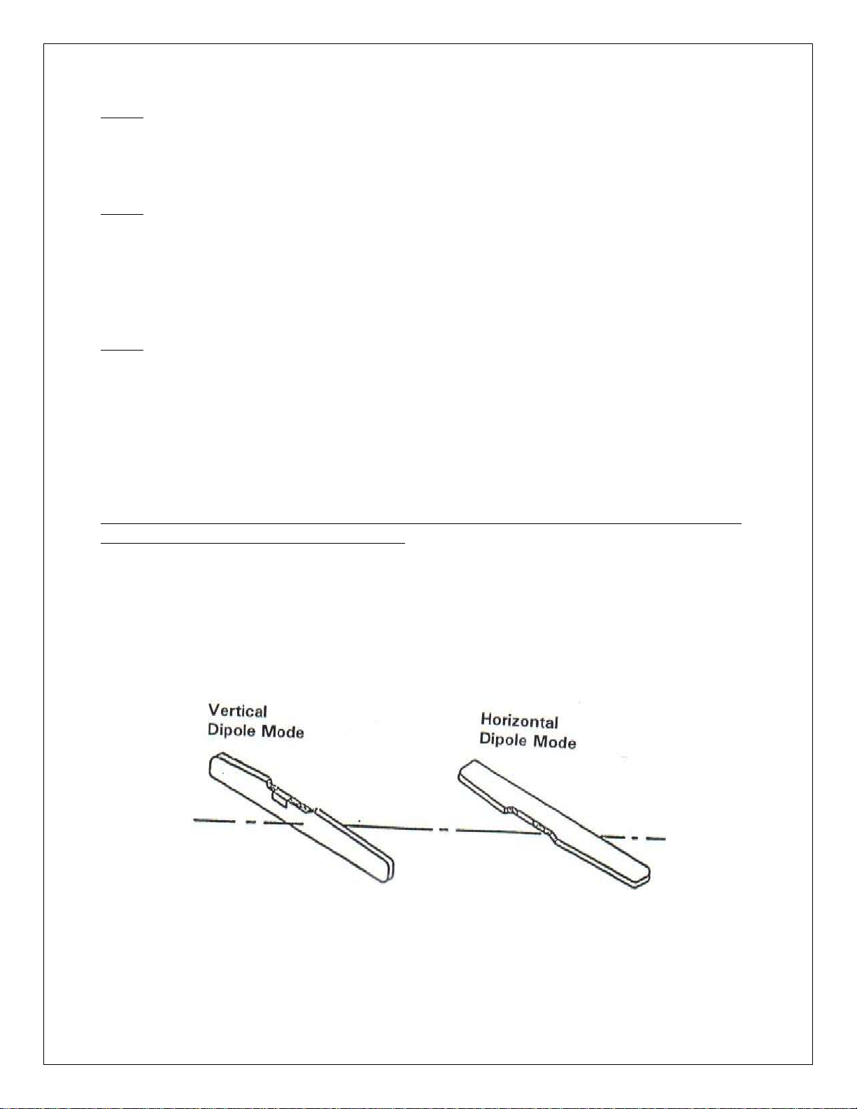
To null the EM38-MK2, lift the instrument to a height of about 1.5 meters (5 feet) above the
ground and place in the horizontal dipole mode of operation (Fig. 1). Set the Mode switch to the
1 m position and null the I/P meter to indicate zero by 1 m control. The EM38-MK2 is
satisfactorily nulled when the instrument at a height of 1.5 meters the I/P meter reads
approximately zero (± 10 mS/m).

7
2.3 Instrument Zero
This adjustment should be carried out at the beginning of each day at the first survey station and
should be checked thereafter two times a day or more often when making measurements over
ground of low conductivity. As referred to earlier, this adjustment is used to accurately set the
instrument zero so that if the unit were taken to a great height above the earth (so as to no longer
respond to terrain conductivity) it would actually read zero. As with all measurements, it is
carried out with the long axis of the instrument horizontal as shown in Fig. 1.
The Mode switch is now in the 1 m position. Lift the instrument to a height of approximately 1.5
meters (5 feet) above the ground. The exact height is not critical but this height should be
reasonably accurately maintained (± 5 cm or 2 inches) throughout the zeroing procedure. With
the instrument in the horizontal dipole mode of operation (Fig.1) adjust the Q/P Zero control so
that the Q/P meter reads approximately 50 mS/m. Note the meter reading in mS/m which we
shall call H. Now without changing the instrument height, rotate the instrument about the long
axis to the vertical dipole mode (Fig. 1) and once again read the Q/P meter. Note the new
reading which we shall call V. Now it can be shown that, regardless of any layering in the earth,
with the instrument at a height of 1.5 meters V should equal twice H; conversely if V is not equal
to twice H we know that the zero is incorrectly set.
We can alter the instrument zero arbitrarily by adjusting the Q/P Zero Control. However we
know that we must adjust this control by an amount such that when we repeat the vertical and
horizontal dipole measurements after the adjustment (again at 1.5 meters) the new Q/P meter
readings, which we shall call Vand H, must satisfy V=2H. Let C be the amount by which we
alter the meter reading by adjusting the Q/P zero Control. How much should C be? If V and H
are the readings before the adjustment and Vand Hare the readings after, then, since the
correction C affects both V and H equally, V=V+C and H=H+C. But C has been chosen so that
V=2Hand therefore
V
HV C
H C
''
2
which can be re-arranged to give C as
Thus having obtained V and H, the initial meter readings in the vertical and horizontal dipole
modes respectively, to set the zero correctly we first calculate C=V-2H, and then with the
instrument in either position we adjust the Q/P Zero Control so as to alter the meter reading by
the amount C (in the direction of higher conductivity if C is positive, lower conductivity if C is
negative). Repeating the vertical and horizontal dipole measurements should now give V =2H
and the zero is correctly set.
C = V-2H

8
An example will help to illustrate this procedure. Suppose that with the instrument at 1.5 m
height the meter reads 12 mS/m in the horizontal dipole mode and 35 mS/m in the vertical dipole
mode.
Then H = 12 mS/m
V = 35 mS/m
and we calculate C = 35-2x12 = +11 mS/m
With the instrument at 1.5 meters and in the horizontal dipole mode (and thus still reading 12
mS/m) we now adjust the Q/P Zero to increase the meter reading by 11 mS/m and thus make the
new reading H = H+C = 12+11 = 23 mS/m. If we rotate the instrument to the vertical dipole
mode it will now read 46 mS/m (which is twice 23) since the 35 mS/m has also been increased
by 11 mS/m. The zero is correctly set.
Again, suppose that the readings are
H = 14 mS/m
V = 16 mS/m
we calculate C = 16-2x14 = -12
and with the instrument at 1.5 meters height and in the horizontal dipole mode we now adjust the
Q/P Zero so as to reduce the horizontal dipole reading by 12 i.e., from 14 to 2, whereupon when
we rotate the instrument to the vertical dipole mode it will read 16-12=4, which is twice 2.
Again the zero is correctly set.
It was stated at the introduction to this section that this adjustment should be carried out at the
first survey station at the start of each day. Suppose that this site happens to be a region of very
high conductivity, say 1,000 mS/m to take an extreme example. If the conductivity is uniform
with depth at an instrument height of 1.5 meters it can be shown that the correct value of V will
be 100 mS/m and of H 53 mS/m for the 1 m coil separation. The accuracy of the zero setting
will be for 1 m coil separation, of the order of 6 mS/m and less for 0.5 m coil separation. This is
perfectly adequate for regions where the ground conductivity is 1,000 mS/m, but if the
conductivity falls to a few tens of mS/m an error of 6 mS/m in the zero setting would become
very serious. A small change in the zero setting will have negligible effect on the accuracy of
the previous high conductivity readings and will greatly improve the accuracy in low
conductivity areas.
In setting the zero, the operator will occasionally find that, on rotating the EM38-MK2 from the
horizontal dipole position where he got H to the vertical dipole mode to get V the meter reading
does not change, i.e., V=H. The answer to this puzzle is that he is standing over ground that is so
resistive that at 1.5 meters height the EM38 no longer responds to the conductivity. The
procedure outlined above still works however; now C=V-2H = -H, so that he will adjust the Q/P
zero control to reduce the meter reading by H which, of course, adjusts it to read H =0. Rotating
the instrument will give V =0 as well.

9
Particularly over resistive ground the operator must ensure that, when setting the instrument zero
he is not near fences, cars or other large metallic objects. The reason for this is that the theory
wherein V =2H applies only for a uniform or a horizontally layered earth. The presence of
large metallic objects will usually affect H more than V, and will thus give an error in the zero
setting. The operator must also make sure that the ground is laterally uniform for a few meters
on either side of the site where he is setting the zero. He must not, for example, attempt to set
the zero in an abandoned landfill site where there are probably buried metallic objects, without
first making sure that the surrounding area is reasonably uniform by carrying out a quick
preliminary EM38-MK2 survey.
It should be noted that if the operator does not want to use the Q/P zero to physically alter the
zero setting during the survey, he should take readings of V and H (with the instrument at 1.5
meters every so often during the day. Then, when he is doing the data plotting he should
calculate C, using the above quotation and add or subtract the value of C to the survey readings
to correct them using linear interpretation as necessary. In the first example given above, 11
mS/m would be added to the readings, and in the second example 12 mS/m would be subtracted
from them.
2.4 Final Inphase Nulling
It was stated above that the inphase nulling was required in order to cancel or null the large
primary signal from the transmitter so that it does not overload the electronic circuitry, thus the
nulling procedure was carried out before setting the instrument zero, as described above.
Unfortunately the magnetic susceptibility of soils causes an additional signal to be picked up by
the receiver coil when the EM38-MK2 is located close to or is lying on the surface of the ground.
Fortunately this signal decreases rapidly with the instrument height above the ground and is
negligible at a height of 1.5 meters.
The additional signal is dealt with in one of two ways. If the survey is to be carried out in only
the vertical or horizontal dipole mode the instrument is simply placed on the ground in the
appropriate position and the residual signal arising from the magnetic susceptibility is nulled out
exactly as described in Section 2.2 (except that the instrument is on the ground).
In the event that the zero level is to be checked during the survey, the nulling procedure should
be repeated with the instrument at 1.5 meters before the zero check is carried out, and again
when the instrument is placed back on the ground for further conductivity measurements. The
magnetic susceptibility of the soil generally varies relatively slowly with location so that
checking the null on the ground every half hour or so is usually sufficient.
Even though the EM38-MK2 with two coils separation provides information from two different
depths, sometimes surveys are carried out in both the vertical and horizontal dipole
configurations in order to obtain more information about the layering, as described later in this
note. Unfortunately, the signal from the susceptibility causes a positive meter deflection in the
vertical dipole mode and a negative meter deflection in the horizontal dipole mode, so that even
though the instrument is correctly nulled for a vertical dipole measurement, re-nulling is
necessary for the horizontal mode measurement, significantly slowing survey speed. However,
this procedure must be followed when making accurate measurements in both the vertical and
horizontal dipole modes on low conductivity ground having significant magnetic susceptibility.

10
On some occasions it may be quicker to perform the survey twice, first in one mode and then in
the other.
If minimal effect from any susceptibility variations is desired (for example in archaeological
applications) then the inphase nulling procedure described above must be carried out before
every measurement and the faster way is probably to perform the survey twice, once in each
dipole.
2.5 Equipment Sensitivity Checks
To approximately check the sensitivity of the instrument, with the instrument at 1.5 meters in the
horizontal dipole position set the Mode switch to the 1 m mark and rotate the Q/P zero control
clockwise one turn. Meter should change between 20 and 28 mS/m, for 1 m coil separation and
28 and 30 mS/m for 0.5 m coil separation. Make sure that the zero control is reset to its original
position.
2.6 Automatic Calibration of EM38-MK2
An optional retractable monopod set-up in combination with data logger is provided for an
automatic calibration of EM38-MK2. The set-up provides means of automatic zeroing of the
EM38-MK2. Figure 8 shows the calibration set-up with the instrument in the vertical (VD) and
horizontal (HD) dipole mode, the two geometry used during the automatic calibration of the
instrument. The detailed description of the calibration procedure is described in the EM38-MK2
logger manual.
2.7 Marker Switch
The orange push button switch on the unit front panel can be used during digital data recording
to either initiate recording of a data point in “manual” recording mode or mark a particular
station during the automatic mode recording. More detailed information is provided in the
EM38-MK2 logger manual.
3. SURVEY PROCEDURES
To carry out a survey with the EM38-MK2, one simply lays the instrument on the ground to take
a reading. This can be done either in the vertical dipole mode or in the horizontal dipole mode,
with important differences in the depth response to be described later in this manual.
The EM38-MK2 yields good spatial resolution and measurement stations should be as close as a
meter apart (0.5 m for 0.5 m coil separation) if maximum resolution is to be employed. The
decision as to the correct station spacing will be based on an estimate of the lateral dimensions of
the anticipated conductivity anomalies. Since measurements can be made very quickly it is
better to have too many measurements with good spatial resolution rather than too few.
This instrument is a sensitive detector of small changes in ground conductivity and is responsive
to metal objects either in or on the ground or on the operator. Metal chains around the neck or
wrist, metal wristwatch straps, metal framed glasses, steel supports in boots, coins, keys, or
knives in pockets can be offenders when they are located close to the coils (which are at either

11
end of the instrument) either when on survey or when the null or zero is being set. To check
whether a metal object is giving a detectable response simply move the object a few meters away
from the instrument and note whether the reading changes. No change -- no problem.
How near can the operator approach a conductive object such as a pipe, fence, etc., and still
ensure that the readings are accurate? In a laterally uniform ground the EM38-MK2 should read
the same regardless of the azimuth of the long axis (i.e., whether it is pointing north/south or
east/west). Any significant difference in the reading in two directions at right angles is an
indication of a significant lateral disturbance. To check whether a pipe or fence is producing an
erroneous reading make two measurements of the ground conductivity, one reading with the long
axis pointing to the object and a second reading at right angles. If the two readings differ by
more than 10% a significant disturbance is being felt and the measurement point must be located
further away from the object.
It should be noted when traversing a pipe on a survey line perpendicular to the pipe direction in
the vertical dipole mode that the reading over the pipe may decrease and attempt to go negative.
If the goal is to locate the pipe one should again rotate the instrument 90oso that the long axis is
parallel to the pipe in which case the apparent conductivity reading becomes a maximum when
(a) the instrument is directly over the pipe and (b) also pointing in the same direction as the pipe.
These remarks apply in the vertical dipole mode, which should be used for the detection of pipes
since the exploration depth is greatest. It is, of course, assumed that the pipe is conductive i.e., is
made of iron, steel or copper.
4. ELECTRICAL INTERFERENCE
Occasionally electrical interference will be encountered, either from cultural sources (50/60 Hz
power lines, industrial noise) or from atmospheric electricity (spherics). Noise from cultural
sources will often manifest itself as slow or rapid semi-periodic oscillations of the output meter
reading which must be averaged out by the operator. The amplitude of these excursions may be
a function of the coil orientation and will also be largest on the most sensitive (low conductivity)
range.
Atmospheric noise will usually show itself as sporadic changes of the meter reading, usually
most severe in the horizontal dipole mode. In this case the receiver operator must again average
out the noise, or restrict himself to the vertical dipole mode of operation, or wait until the
spherics have decreased.
5. NOTES ON SURVEY INTERPRETATION
5.1 Linearity of Response
The indicated apparent conductivity measured with the EM38-MK2 is accurate over most of the
range of the instrument.
5.2 Relative Response with Depth
TN-6 discusses in detail the fact that it is possible to calculate the relative response from material
at different depths for both the vertical and horizontal dipole mode coil configurations. The

12
results for the EM38-MK2 are shown in Fig. 2A for 1 m coil separation and 2B for 0.5 m coil
separation where the function gives the fractional response to the meter reading from a thin
horizontal sheet of thickness dz buried at a depth z. We see that in the vertical dipole mode the
relative sensitivity to near surface material is very low (being zero right at the surface), that the
sensitivity increases with depth, becomes a maximum at about 0.4 (0.2 m for 0.5 m coil
separation) meters and decreases slowly thereafter. On the other hand in the horizontal dipole
mode of operation the relative sensitivity is greatest to material at the surface, and decreases
thereafter with depth. The large difference in the response to near surface material in the two
coil configurations is important; the horizontal dipole mode will be relatively sensitive to
variations in the near surface whereas the vertical dipole mode will be insensitive.
This difference in sensitivity allows a quick method for determining whether the near surface
material is more or less conductive than material at depth. One simply places the instrument on
the ground in the vertical dipole mode, notes the reading, rotates the instrument to the horizontal
dipole mode and again notes the reading. If the second reading is greater than the first, the near
surface material is the more conductive and vice versa. If both readings are essentially the same
then the conductivity of the ground is essentially uniform to a depth of about 1.5 meter, the
effective depth of exploration for the EM38-MK2.
5.3 Multi-Layer Calculations
The functions Rv(z/s) and Rh(z/s) referred to in TN-6 are illustrated in Fig.3. It will be recalled
that these curves give the fractional response arising from all material below depth z for both the
vertical and horizontal dipole modes (the curves in TN-6 refer to the depth normalized with
respect to the intercoil spacing which for the EM38 is one meter so the curves apply directly).
These curves, when used with the techniques outlined in TN-6, allow simple calculation of the
instrument response in either coil configuration to a multi-layered horizontally stratified earth.
5.3.1 Variation of EM38 Response with Height
The curves of Fig. 3 also give the decrease of the apparent conductivity reading when the
instrument is lifted above a uniformly conductive earth, since in general for a two-layered earth
σaσ1[1 R(z1)] σ2R(z1)
and if the first medium is air, with conductivity 1=0
σaσ2R(z1)
where z1is now the instrument height above the ground.
Examination of the curves shows that in the vertical dipole mode an increase of elevation from 0
to 20 cm results in a reduction of apparent conductivity reading to 92.5% of the surface reading,
whereas in the horizontal dipole mode the reading is reduced to 68%. We thus see that the

13
instrument reading in the horizontal dipole mode is more sensitive to instrument height or
conversely that in regions where the surface topography varies rapidly on the order of 10-20 cm
we can expect some scatter in the horizontal dipole readings.
In the event that the earth is two-layered it is possible to resolve this geometry by lifting the
EM38 above the ground and making a sequence of measurements at various heights in both the
horizontal and vertical dipole mode. The curves shown in Figs. 4 and 5 illustrate the fall-off
with height of the apparent conductivity for a variety of two-layered configurations; to employ
them one simply plots the measured apparent conductivity with height on a piece of transparent
paper to the same scale as the figures and translates the plot vertically or horizontally across the
various figures until a match is obtained. The various layer parameters are then calculated as in
the following example, using the measured values of apparent conductivity from Table 1.
TABLE 1
Apparent Conductivity (mS/m)
h (m) Vertical Horizontal
Dipole Dipole
0.0 93 77
0.5 62 36
1.0 41 23
1.5 29 16
2.0 23 12
By translating this data as described above on top of the various curves of Fig. 4 we see that
good agreement is achieved for t=0.3 m and k= 2/1=2. Furthermore we note that, in the vertical
dipole mode a/1=1.85 when a=93 mS/m. Therefore 1=a/1.85=50 mS/m, 2=2 1=100
mS/m, and t=0.3 m, fully resolving the two-layered geometry.
It should be noted that these curves are also useful for a three-layered earth geometry where the
upper layer is relatively resistive compared with the other two, as illustrated in Fig. 6. In this
case we simply assume that 1=0 and that this layer effectively prevents us from laying the
instrument on the more conductive second layer. The fall-off with height of the apparent
conductivity over such a geometry will still be as shown in Figs. 4 and 5 except that when a good
match to one of these curves has been obtained it will be found that at a measured instrument
height of zero meters the appropriate curve will still indicate a finite height, the value of which is
the actual thickness of the upper resistive layer.
The user is cautioned that, to the accuracy with which the measurements can be made, more than
one set of the curves shown in Figs. 4 and 5 may match the field data, in which case he must rely
on other factors (such as knowledge of the probable geology) to decide which model is more
appropriate.

14
5.3.2. Simplified Two-layered Earth Interpretation
In general, a two-layered earth has three unknown quantities, 1, 2, and t, whereas
measurements made with the EM38-MK2 on the ground produce only two measured quantities,
av (the apparent conductivity in the vertical dipole mode) and ah (the apparent conductivity in
the horizontal dipole mode). If one of the two unknown conductivities is much greater than the
other and we may assume that the smaller conductivity is zero we are left with only two
unknowns and the problem is fully resolved. If 1>> 2we obtain the conductivity and the
thickness of the upper (conductive) layer; if 2>> 1we obtain the depth to and the conductivity
of the lower (conductive) layer.
Given ah and av the procedure is as follows: if av > ah calculate the ratio ah / av and with
this ratio use curve (1) Fig. 7 to determine z, the depth to the conductive substrate. Given z, use
Fig. 3 to obtain either Rh(z) or Rv(z) whence
σ2
σah
Rh(z)
σav
Rv(z)
and the problem is solved.
If on the other hand ah > av, calculate av / ah and with this ratio use curve (2) in Fig. 7 to
determine z, the thickness of the conductive upper layer. Given z use Fig. 3 to obtain either
Rh(z) or Rv(z) whence
σ1
σah
1Rh(z)
σav
1Rv(z)
Note that in the event that neither 1>> 2or 2>> 1it is still possible to use this procedure to
define an apparent conductivity and an apparent thickness (or depth) which should be reasonably
valid as long as a reasonable conductivity contrast exists. If the earth has more than two layers
this procedure defines the equivalent two layered earth.
6. MEASURING SOIL MAGNETIC SUSCEPTIBILITY
It is a simple matter to measure the magnetic susceptibility of the upper half meter of the soil
using the EM38-MK2 in the vertical dipole mode. Set the Mode switch to the I/P position so
that the instrument is measuring the inphase component from the ground and lift the instrument
to a height of approximately 1.5 meters above the ground. Set the meter reading to
approximately 50 mS/m using the I/P zero controls and note the apparent conductivity reading at
this height. With the Mode switch still in the I/P position, lower the instrument to the surface
and again measure the apparent conductivity. It will be observed that as the instrument is
lowered, the meter reading initially swings to lower conductivity, then returns to the conductivity

15
which was indicated at the height of 1.5 meters and finally increases to a larger apparent
conductivity.
The magnetic susceptibility (in RMKS units) is then given by
K=57x10-6∆σa(mS/m) (for 1 m)
K=14.5x10⁻⁶∆σa(mS/m) (for 0.5 m)
or in CGS units by
where ais the difference in the apparent conductivity measured when the instrument is on the
ground and elevated to 1.5 meters.
7. OUTPUT UNITS
The EM38 is calibrated so that under the low induction number approximation the quadrature
component output (Q/P) reads directly in apparent conductivity (a). The inphase component
output (I/P) on the EM38-MK2 also reads in units of mS/m; where 28.5 ppt (7.12 for 0.5 m) of
the secondary field relative to the primary field corresponds to 1,000 mS/m.
The following relation can be used to convert mS/m to ppm: 1 mS/m ≡ 28.5 ppm (7.12 for 0.5 m)
where 1 ppm (parts per million) = 1 ppt (parts per thousand)
1000
When the instrument is used with a digital data logger or computer the I/P readings in mS/m are
automatically converted to ppt.
8. CONCLUDING REMARKS
It is hoped that the material given in this manual will assist in survey interpretation. It should be
borne in mind that the strength of the EM38-MK2 lies in the speed and accuracy with which a
reconnaissance conductivity survey can be carried out. While the instrument was not designed
K=
57x10-6
Δσa(mS/m) (for 1 m)
4π
K=
14.5x10⁻⁶
Δσa(mS/m) (for 0.5 m)
4π

16
for detailed sounding of conductivity with depth it gives very useful results when the earth can
be approximated by a two-layer mode.
9. COMMUNICATON WITH EXTERNAL LOGGER
EM38-MK2 is designed to communicate with an external logger in two different ways: a)
through an RS232 serial port via cable connection or b) via a wireless Bluetooth connection. The
choice which to use will depend on the system configuration. For short (up to 10 metres) non
obstructed distances between the logger and the EM38, the wireless Bluetooth communication is
more convenient. For an application like instrument installation on the trailer, where there may
be obstructions between the instrument and the logger, an RS232 cable communication may have
to be used. Note that for proper communication with logger when RS232 port is used, a special
RS232 cable marked “EM38-MK2-4P” must be used.
The obvious advantage of wireless communication is there is no need for a cable and avoidance
of possible interference from the cable if the communication cable is moving around the
instrument sensors.
A more detailed description on the use of two communication method is provided in the EM38-
MK2 Logger Manual.
10. OPTIONAL COMPONENTS
10.1 External Battery
A provision is provided on the instrument front panel for use of an external battery. Depending
on the specific application, trailer mount for example, it may be convenient to use an external
battery to extend the battery service.
The external battery voltage should be between 9 to12 V. The required supply current is 50 mA.
To estimate the approximate service life of the battery, divide battery capacity in mA/h by 50.
For example a small fully charged gel cell battery with a capacity of 1.3 A/h (1300 mA/h) will
give approximately 25 hours of service. Note that the internal battery should not be removed
from the instrument even when the external battery is used.
10.1.1 External Battery Pack
The instrument can be supplied as an option with a rechargeable battery pack. The pack contains
a battery that when fully charged will last for about 25 hours of continuous operation.
To determine if the battery will require charging or replacing soon, the battery voltage can be
measured with a battery tester.
To check the battery voltage with a battery tester, insert the tester into the socket on the battery
pack panel.

17
The fully charged battery will read above 13 V. Recharge the battery if its voltage is below 10.5 V.
The battery can be charged by attaching the battery charger to the connector on the battery pack.
Remember to connect the charger to the battery before applying power to the charger.
Completely charging a full discharged battery takes about 8 hours. To prevent the defective
charger from damaging the instrument power supply PCB, do not change the battery, when the
connected to the EM38-MK2 console.
Figure 9 shows the components of the external battery pack.
10.1.2 External Battery Care
The external battery pack contains Pb/gel type of batteries. Pb/gel batteries work on the same
principle a Pb/acid batteries. Gel is used in the place of acid, and the batteries are sealed. A a
result they can be shipped by parcel post as well as by passenger and cargo aircraft (cf. IATA
Restricted Cargo Regulations, Article 1924).
The Pb/gel batteries can be fully recharged from total discharge several hundred times. If you
typically use only a fractions of the battery capacity before recharging, the number of possible
recharges increases.
The batteries maintain full capacity regardless of the pattern of use. But their capacity will
eventually decrease with age.
From full charge, the batteries will lose 2 to 3% of their charge per month when stored at 20˚C.
Deep Discharge Protection
The Dryfit battery, unlike conventional lead storage batteries, is protected against excessive
discharge. In the event that a battery remains connected to a load for an excessive period of time,
deep discharge protection ensures that the battery can be recharged without permanent damage.
After 30 days of deep discharge, batteries should be recharged for a period of 48 hours. A
completely discharged battery should not be left for longer than 30 days without recharging.
After re charge, it can be expected that the batteries will exhibit a loss in charge capacity,
batteries should be run through a serial of (at least three) cycles of discharge and recharge.
Storage Conditions
It is important that the battery is stored fully charged. After use, set the battery on charge and
keep it on till next use. If it is not possible to keep the battery continuously on charge, it should
be stored fully charged at a mean ambient temperature of +20˚C and recharged after a maximum
of 6 months. At higher temperatures, the period will be shorter, and at lower temperatures, will
be extended. Since the specific gravity of the electrolyte will fall as a state of charge is reduced,
causing the freezing point to rise, only full charged batteries should be stored at extremely low
temperatures. Given that storage in the fully charged state discharge should not be allowed to fall
below 50% of the charged state.

18
10.2 Protective Housing
An optional protective housing (see Figure 10) is designed to give the instrument protection from
dust, mechanical shocks, as well as to improve instrument stability (drift) as a result of sudden
change in environmental temperature. The housing is especially useful when the instrument is in
a cart operating mode. The openings on the housing cover are to allow for connection to the
external battery and to the recording device.
10.3 Extender Arm
A collapsible extender arm (see Figure 11) can be used to conveniently carry the instrument over
the survey area, either in vertical or horizontal dipole mode. The switch on the top of the hand is
connected, via an interconnecting cable, in parallel with the marker switch on the instrument. It
can be used, during digital data recording, to either initiate recording or make markers for
particular stations as described in section 2.7.
Other manuals for EM38-MK2
1
This manual suits for next models
1
Table of contents
Other Geonics Limited Measuring Instrument manuals
Popular Measuring Instrument manuals by other brands

Mobeye
Mobeye WaterGuard-FS CM2300FS user manual

Vision & Control
Vision & Control TOB42/11.0-165-F16-WN Instructions for use

PCE Instruments
PCE Instruments PCE-DC 3 manual

Kobold
Kobold Heinrichs K09 operating instructions

LaserLiner
LaserLiner DistanceMaster Compact operating instructions

AcoustX
AcoustX D2 quick start guide