Geonics Limited EM31-SH User manual

Tel: (905) 670-9580
Fax: (905) 670-9204
GEONICS LIMITED E-mail:geonics@geonics.com
1745 Meyerside Dr. Unit 8 Mississauga, Ontario Canada L5T 1C6 URL:http://www.geonics.com
EM31-SH
OPERATING MANUAL
GEONICS LIMITED
LEADERS IN ELCTROMAGNETICS
8-1745 Meyerside Drive, Mississauga, Ontario Canada L5T 1C6
Tel: (905) 670-9580 Fax: (905) 670-9204
July 2007

Tel: (905) 670-9580
Fax: (905) 670-9204
GEONICS LIMITED E-mail:geonics@geonics.com
1745 Meyerside Dr. Unit 8 Mississauga, Ontario Canada L5T 1C6 URL:http://www.geonics.com
NOTE TO EM31 AND EM34 USERS:
Through the normal course of operation, it is possible
that the battery contacts will become contaminated with
dirt and grit. To clean these contacts use fine sand
paper (#400 or higher) and wipe several times over the
contact.
Ensure that the spring action of the battery holders is
maintained. Bend holder sides slightly if necessary.

Tel: (905) 670-9580
Fax: (905) 670-9204
GEONICS LIMITED E-mail:geonics@geonics.com
1745 Meyerside Dr. Unit 8 Mississauga, Ontario Canada L5T 1C6 URL:http://www.geonics.com
Section
Subject Page
Technical Specifications i
1.0 Introduction 1
2.0 Operation Instructions 10
2.1 Ground Conductivity Measurements 10
2.1.1 Initial Set-up Procedure 10
2.1.2 Equipment Functional Checks 14
2.1.3 Operating Procedure 16
2.2 Buried Metal Detection 18
2.2.1 Set-up and Operating Procedure 18
3.0 Instrument Calibration 20
3.1 Null Calibration 20
3.2 Absolute Calibration 20
4.0 Survey Technique 22
5.0 Data Interpretation 26
5.1 Uniform Halfspace 26
5.2 Multi-Layered Earth 27
6.0 Case Histories: Electromagnetic
Non-Contactin
g
Ground Conductivit
y
Ma
pp
in
g
31

EM31-SH SPECIFICATIONS
MEASURED
QUANTITIES
(1) Apparent conductivity of the ground in
millisiemens per meter (mS/m)*
(2) Inphase component in parts per thousand
(ppt) of the ratio of the secondary to
primary magnetic field
PRIMARY FIELD SOURCE
SENSOR
INTERCOIL SPACING
OPERATING FREQUENCY
POWER SUPPLY
(For Main Console)
CONDUCTIVITY RANGES
INPHASE RANGE
DATA LOGGER CAPACITY
MEASUREMENT RESOLUTION
MEASUREMENT ACCURACY
NOISE LEVELS
OUTPUT PORT FOR
REAL TIME LOGGING
DIMENSIONS
WEIGHT
Self-contained dipole transmitter
Self-contained dipole receiver
2.0 meters
9.8 kHz
8 disposable alkaline “C” cells (approx.
20 hrs. life continuous use)
19, 199, 1999 mS/m
±6 ppt
a) 8,000 records (two components)
b) 6,000 records (two components + GPS)
0.1% of full scale
+5% at 20 mS/m
0.1 mS/m, 0.03 ppt
RS-232C, 9,600 baud rate
Boom : 2.35 meters extended
: 1.36 meters stored
Shipping Case : 144 x 21.5 x 36 cm
Instrument Weight : 9.0 kg
Shipping Weight : 20.5 kg
*Millisiemens per meter (mS/m) are the same as millimhos per meter (mmho/m)
i

EM31-SH MANUAL Page 1
1.0 INTRODUCTION
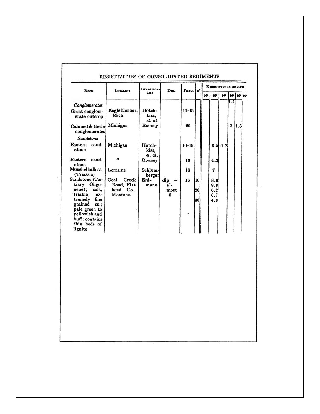
Measurement of ground resistivity is one of the oldest
geophysical techniques. Table 1, taken directly from
Heiland*, lists typical values of resistivity for a variety
of geological materials (pages 4-8). The values given are in
ohm-centimeters and must be divided by one hundred to give
ohm-meters.
It will be observed that in most cases the actual resistivity
itself is not diagnostic and a knowledge of the way in which
the resistivity varies laterally and with depth is of great
importance, since this permits us to “see” features as a
result of their shape rather than their actual resistivity
values. There is thus a requirement for instrumentation which
permits the rapid and accurate measurement of terrain
resisitivity. Since the EM31 does not require electrical
contact with the ground it fulfils this objective.
The basic principle of operation of EM31 is simple. With
reference to Figure 1 a transmitter coil located at one end
of the instrument induces circular eddy current loops in the
earth. Under certain conditions fulfilled in the design of
the EM31 the magnitude of any one of these current loops is
directly proportional to the terrain conductivity in the
vicinity of that loop. Each one of the current loops
generates a magnetic field which is proportional to the value
of the current flowing within that loop. A part of the
magnetic field from each loop is intercepted by the receiver
coil and results in an output voltage which is therefore also
linearly related to the terrain conductivity.
* Heiland, C.A. Geophysical Exploration. Hafner Publishing Co., New York 1968

EM31-SH MANUAL Page 2
Figure 1: Induced Current Flow in Ground
This instrument is calibrated to read the correct conductivity when
the earth is uniform. In the event that the earth is layered, with
each layer of different conductivity, the instrument will read an
intermediate value as discussed in more detail in Section 5.2.
The unit of conductivity used is the millimho per meter (the same
as millisiemens per meter). To obtain resistivity in ohm-meters
the instrument reading is divided into 1000 – i.e., a reading of
four millimhos per meter divided into 1000 gives two hundred and
fifty ohm-meters.

EM31-SH MANUAL Page 3
1.0 INTRODUCTION (Cont’d)
Theoretical calculations show, as will be quickly evident to
the operator, that the reading obtained is essentially
independent of the orientation of the instrument with
respect to the earth. There is, however, a small dependence
on the height above the ground; lifting the instrument from
the surface of a uniform earth to the height of about 0.7
meter results in a reduction in the reading of 21%. The
calibration has been adjusted at the factory so that the
instrument reads correctly over a uniform half-space when
worn as shown on page 16. If the earth is layered, raising
the instrument from the surface of the earth to the normal
operating position can result in a reading which stays
constant or even increases slightly with height. In general
readings made with the instrument at hip height will be
sufficiently accurate, but for maximum accuracy the
instrument can be laid on the ground as will be discussed in
Section 5.2.
There are two components of the induced magnetic field
measured by the EM31. The first is the quadrature-phase
component which gives the ground conductivity measurement as
described. The second is the inphase component used
primarily in the EM31 for calibration purposes. The inphase
component, however, is significantly more sensitive to large
metallic objects and hence, very useful when looking for
buried metal drums (see Section 2.2).

EM31-SH MANUAL Page 4
Table 1A: Resistivities of Igneous and Metamorphic
Rocks

EM31-SH MANUAL Page 5
Table 1B: Resistivities of Consolidated Sediments

EM31-SH MANUAL Page 6
Table 1B (cont’d): Resistivities of Consolidated
Sediments

EM31-SH MANUAL Page 7
Table 1B (cont’d): Resistivities of Consolidated
Sediments

EM31-SH MANUAL Page 8
Table 1C: ResistivitiesofUnconsolidatedFormations

EM31-SH MANUAL Page 9
EM31-SH FRONT PANEL FEATURES

EM31-SH MANUAL Page 10
2.0 OPERATING INSTRUCTIONS
The EM31 can be used both to measure the electrical
conductivity of the ground and to detect buried metal
objects. Section 2.1 describes the procedure for
measuring ground conductivity and Section 2.2 for buried
metal detection.
2.1 GROUND CONDUCTIVITY MEASUREMENTS
2.1.1 Initial Set-up Procedure
a)1 Before undoing the bottom holder and releasing the
receiver coil boom, check the battery condition, plus and
minus, by setting the Mode switch to the OPER position
and rotate the Range switch counter-clockwise to the BATT
position. Turn data logger on and run polycorder program
EM31-MK2, as per EM31-MK2 data logger manual. If the
display reads above ±4.4 the batteries are in good
condition, otherwise replace the batteries with a fresh
set of C size alkaline batteries. To get access to
batteries, undo the battery pack fastener and pull the
pack out of the console.
a)2 Digital Recorder (Polycorder) Batteries
-Main Batteries
The Polycorder is shipped with a special battery pack
that contains six standard “AA” nickel-cadmium
rechargeable batteries
-Backup Batteries
The backup battery is a half-sized AA lithium cell. This

EM31-SH MANUAL Page 11
long life “non-replaceable” battery will maintain the
Polycorder’s memory for at least five years. It can be
replaced if necessary, but that must be done at the
factory.
-Battery Life
Ni-cad battery life with the Polycorder on the shelf is
about 18 months. Depending on the program and how
efficient the operator is, battery life for fully charged
batteries can be anywhere from 30 to 50 hours.
The Polycorder’s operating system completely protects you
from losing data because the battery has run down.
Here’s how it works: as the Polycorder operates, drawing
from the main supply, it monitors the batteries so that
it can warn you when they need to be charged. Once
battery voltage drops below a certain threshold, you will
see a flashing message:
each time you press ESC, and each time you press ENTER
while executing a program. CHARGE YOUR POLYCORDER
BATTERIES AS SOON AS YOU CAN if you see this message.
If you fail to charge the batteries and voltage drops
below a second threshold, the Polycorder displays the
message:
LOW BATTERIES

EM31-SH MANUAL Page 12
Then it turns itself off and begins drawing from the
backup. The polycorder “knows” not to operate on the
backup battery alone. If you try to turn it on again, the
polycorder immediately displays CHARGE BATTERIES and
shuts down again. Hence the only demand on the backup
cell is the small current required to maintain memory,
which the battery can deliver for several years.
-Charging Batteries
Contrary to what you might think, it’s good practice to
let the main batteries discharge just short of seeing the
battery message. If you habitually recharge Ni-cad
batteries when they are only slightly discharged, you
will get less and less use out of each recharging.
Obviously you will need to balance this with the risk of
being forced to suspend data collection because the
Polycorder has shut down.
The Polycorder comes with a 120 VAC battery charger. To
charge the batteries connect the charger output to the
serial I/O Connector on the polycorder, and plug charger
input into the 120 VAC source. In countries with 220 VAC
power line use step-down transformer between 220 VAC
source and 120 VAC charger.
Note that the logger can be removed from the console for
charging and data dumping by releasing two logger lock
screws on each side of the console and pulling the logger
straight out.
CHARGE BATTERIES
CHARGE BATTERIES
CHARGE BATTERIES
CHARGE BATTERIES

EM31-SH MANUAL Page 13
-Replacing Batteries
Ni-cad batteries can be recharged several hundred times,
but effective working life continually decreases.
Eventually the batteries need to be replaced. It is a
good practice to replace the battery pack annually.
You can change batteries without losing memory.
To replace the battery pack, turn the Polycorder off and
lay it face down on a desk or table top. Loosen the six
screws, pull the case bottom straight up, and lay it
aside for the moment. Do not loosen or remove the six
hex standoffs. Remove the bracket from around the
battery pack. Unplug the battery connector. Remove the
battery pack. Place the new battery pack in the same
position as the old one. Plug in the two-pin connector.
Place the bracket around the battery pack and align the
six holes with the holes in the case. Drop the six outer
screws in place and tighten them down. Reload program if
necessary, see section II of Data Logger Operating Manual
for further information on loading of the program.
b) Turn the instrument ON by setting the Mode switch to the
OPER position and check the zero reading. The Range
switch should be set to the least sensitive position
1,000 mS/m (this minimizes any external noise
interference while checking the zero position).
Tolerance for this check is ±1 mS/m on the conductivity
meter. If a zero adjustment is required adjust the DC
ZERO CONTROL by using a small flat-head screwdriver to
obtain a zero reading. The control could be accessed
through the small hole on the side of the console box.
Do not adjust Q/F control at this point.

EM31-SH MANUAL Page 14
c) Turn the instrument OFF using the MODE switch, before
connecting the receiver coil, then align and connect the
receiver coil tube to the main frame tube. The
instrument is now ready to proceed with the functional
checks.
2.1.2 Equipment Functional Checks
The Range switch should be set at 100 mS/m position for
all the following tests. (If the conductivity reading is
over full scale i.e., greater than 100 mS/m, see note at
end of this section).
a) Set the Mode switch to the OPER position and adjust the
inphase (I) reading to zero using the COARSE and FINE
COMPENSATION controls. Tolerance ±0.1 ppt.
b) To check the phase of the instrument set the Mode switch
to the PHASE position. Note the conductivity (Q) reading
and rotate the COARSE control one step clockwise. If the
conductivity reading remained the same (tolerance ±0.2),
the phase is already correct; return the COARSE control
to its original position (one step counter clockwise) and
no further adjustment is necessary.
If there is a difference in the conductivity readings
taken before and after the COARSE control was rotated one
step clockwise then a phase adjustment is required. With
the COARSE control in its original position adjust the
PHASE potentiometer about ¼ turn clockwise and note the
new conductivity reading. Rotate the COARSE control one
step clockwise, take a reading, and return the COARSE
control to its original position. If the difference in
readings has decreased, repeat the procedure using a
further clockwise adjustment, until rotating the COARSE
control the one step clockwise produces no change in the
reading (tolerance ±0.2 mS/m).

EM31-SH MANUAL Page 15
If, on the other hand, the difference in readings has
increased, the PHASE potentiometer should be rotated in a
counter clockwise direction instead and the procedure
described above repeated until there is no change in the
readings. Always remember to set the COARSE control back
to its original position. This can be confirmed by
checking that the inphase (I) reads zero with the mode
switch set to OPER mode. If it does not read zero, use
the coarse and fine compensation controls to obtain zero
of the inphase reading.
c) To check the sensitivity of the instrument, set the Mode
switch to the COMP position and rotate the COARSE control
clockwise one step. The conductivity reading should
change between 78 to 82 mS/m. It is unlikely that the
sensitivity of the instrument will vary, however, it may
be useful to record the actual reading for comparison at
a later date.
Return the COARSE switch to its original setting and set
the mode switch to OPER. The EM31 is now ready to make
ground conductivity measurements.
NOTE:a) When conducting the functional tests over ground of
conductivity greater than 100 mS/m, the Range switch
should be set at the 1000 mS/m range. At whatever level
the Range switch is in, the reading taken in (c) should
still be between 78 and 82 mS/m.
b) The maximum output range of the instrument is 20 mS/m or
200 mS/m, or 2,000 mS/m for conductivity component, and
6 ppt for inphase component.
c) At the end of the survey always remember to turn off both
data logger and main console

EM31-SH MANUAL Page 16
2.1.3 Operating Procedure
a) Positioning the instrument with the should strap adjusted
so that the instrument rests comfortably on the hip as
shown, turn the Mode switch to the OPER position and
rotate the Range switch so that the conductivity reads in
the upper two-thirds of the full range. The conductivity
display is now reading ground conductivity directly in
mS/m and full scale reading (minus 99% of overage) is
indicated by the Range switch.
Normal Operating Position – Vertical Dipoles
b) The instrument can be operated in either of two dipole
modes – vertical or horizontal. The instrument response,
as a function of depth, varies significantly between the
two modes. It is important to recognize that the vertical
dipole mode provides twice the effective depth of
exploration as the horizontal dipole mode – 4 m and 2 m,
respectively. (A complete discussion of the vertical and
horizontal dipole modes is provided in Geonics Technical
Note TN-6).
Table of contents
Other Geonics Limited Measuring Instrument manuals