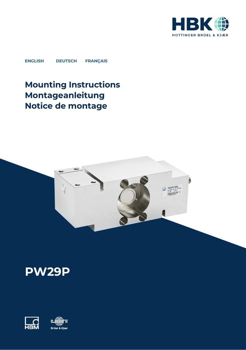
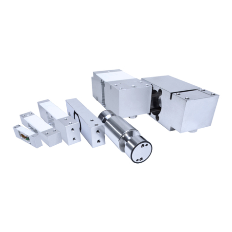
HBK C2 User manual

C2
ENGLISH DEUTSCH FRANÇAIS ITALIANO
Mounting Instructions
Montageanleitung
Notice de montage
Istruzioni per il montaggio

Hottinger Brüel & Kjaer GmbH
Im Tiefen See 45
D-64293 Darmstadt
Tel. +49 6151 803-0
Fax +49 6151 803-9100
www.hbkworld.com
Mat.: 7-2002.0144
DVS: A00674 05 YI0 02
01.2022
EHottinger Brüel & Kjaer GmbH
Subject to modifications.
All product descriptions are for general information
only. They are not to be understood as a guarantee of
quality or durability.
Änderungen vorbehalten.
Alle Angaben beschreiben unsere Produkte in allge
meiner Form. Sie stellen keine Beschaffenheits- oder
Haltbarkeitsgarantie dar.
Sous réserve de modifications.
Les caractéristiques indiquées ne décrivent nos
produits que sous une forme générale. Elles
n'impliquent aucune garantie de qualité ou de
durabilité.
Con riserva di modifica.
Tutti i dati descrivono i nostri prodotti in forma
generica e non implicano alcuna garanzia di qualità o
di durata dei prodotti stessi.

C2
ENGLISH DEUTSCH FRANÇAIS ITALIANO
Mounting Instructions

C2
TABLE OF CONTENTS
2
TABLE OF CONTENTS
1 Safety Instructions 4................................................
2 Markings used 7....................................................
3 Scope of supply and equipment variants 8.............................
3.1 Scope of supply 8...................................................
3.2 Equipment variants 8................................................
3.3 Accessories 9......................................................
4 General application instructions 10....................................
5 Structure and mode of operation 11....................................
5.1 Transducer 11.......................................................
5.2 Strain gage covering agent 11.........................................
5.3 Inline amplifier 11....................................................
6 Conditions on site 12.................................................
6.1 Ambient temperature 12..............................................
6.2 Moisture and corrosion protection 12...................................
6.3 Deposits 12.........................................................
6.4 Effect of ambient pressure 12..........................................
7 Mechanical installation 14............................................
7.1 Important precautions during installation 14..............................
7.2 General installation guidelines 14.......................................
7.3 Mounting 15........................................................
8 Electrical connection 16..............................................
8.1 Connection to a measuring amplifier without an integrated amplifier 16......
8.1.1 General connection information 16.....................................
8.1.2 Connection to an M12 plug without integrated amplifier 17.................
8.1.3 Extension cables and cable shortening 17...............................
8.1.4 EMC protection 17...................................................
8.1.5 TEDS transducer identification 18......................................
8.2 Connecting sensors with an integrated amplifier 18.......................
8.2.1 General information 18...............................................
8.2.2 Connection 18.......................................................

C2
SAFETY INSTRUCTIONS
4
1 SAFETY INSTRUCTIONS
Intended use
Force transducers in the C2 type series are designed solely for measuring static and
dynamic compressive forces within the load limits stated in the specifications. Any other
use is not appropriate.
To ensure safe operation, it is essential to comply with the regulations in the mounting
instructions, the safety requirements listed below, and the data specified in the technical
data sheets. It is also essential to observe the applicable legal and safety regulations for
the relevant application.
Force transducers are not intended for use as safety components. Please also refer to
the "Additional safety precautions" section on the following page. Proper and safe opera
tion of force transducers requires proper transportation, correct storage, setup and
mounting, and careful operation.
Load‐carrying capacity limits
The information in the technical data sheets must be complied with when using force
transducers. The respective specified maximum loads in particular must never be
exceeded. The following limits set out in the technical data sheets must not be exceeded:
SForce limits
SLateral force limits
SBending moment and torque
SBreaking forces
SPermissible dynamic loads
STemperature limits
SElectrical load limits
Please note that when several force transducers are interconnected, the load/force distri
bution is not always uniform.
Use as a machine element
Force transducers can be used as machine elements. When used in this manner, note
that to favor greater sensitivity, force transducers were not designed with the safety fac
tors usual in mechanical engineering. Please refer here to the "Load-carrying capacity
limits" section and Chapter 11, starting on page 23.
Accident prevention
The prevailing accident prevention regulations must be taken into account, even though
the nominal (rated) force values in the destructive range are well in excess of the full
scale value.

5
C2
SAFETY INSTRUCTIONS
Additional safety precautions
Force transducers cannot (as passive transducers or as sensors with integrated ampli
fiers) implement any (safety-relevant) cutoffs. This requires additional components and
design measures, for which the installer and operator of the plant is responsible.
In cases where a breakage or malfunction of the force transducer would cause injury to
persons or damage to equipment, the user must take appropriate additional safety pre
cautions that meet at least the applicable safety and accident prevention regulations (e.g.
automatic emergency shutdown, overload protection, catch straps or chains, or other fall
protection).
The downstream electronics should be designed so that failure of the measurement sig
nal cannot lead to secondary failures.
General dangers of failing to follow the safety instructions
Force transducers are state-of-the-art and reliable. There may be dangers involved if the
transducers are mounted, set up, installed and operated inappropriately, or by untrained
personnel. Every person involved with setting up, starting-up, operating or repairing a
force transducer must have read and understood the mounting instructions and in partic
ular the technical safety instructions. The force transducers can be damaged or
destroyed by non-designated use of the force transducer or by non-compliance with the
mounting and operating instructions, these safety instructions or other applicable safety
regulations (BG safety and accident prevention regulations) when using the force trans
ducers. A force transducer can break, particularly in the case of overloading. The break
age of a force transducer can cause damage to property or injury to persons in the vicin
ity of the force transducer.
If force transducers are not used as intended, or if the safety instructions or specifica
tions in the mounting and operating instructions are ignored, it is also possible that a
force transducer may fail or malfunction, with the result that persons may be injured or
property damaged (due to the loads acting on or being monitored by the force trans
ducer).
The scope of supply and performance of the transducer covers only a small area of force
measurement technology, as measurements with strain gage sensors presuppose the
use of electronic signal processing. Equipment planners, installers and operators should
always plan, implement and respond to the safety engineering considerations of force
measurement technology in such a way as to minimize residual dangers. Pertinent
national and local regulations must be complied with.
Conversions and modifications
The design or safety engineering of the transducer must not be modified without our
express permission. Any modification shall exclude all liability on our part for any dam
age resulting therefrom.

C2
SAFETY INSTRUCTIONS
6
Maintenance
The force transducers of the C2 series are maintenance free. We recommend completing
a calibration on a regular basis.
Disposal
In accordance with national and local environmental protection and material recovery and
recycling regulations, old transducers that can no longer be used must be disposed of
separately and not with normal household garbage.
If you need more information about disposal, please contact your local authorities or the
dealer from whom you purchased the product.
Qualified personnel
Qualified personnel means persons entrusted with siting, mounting, starting up and oper
ating the product who possess the appropriate qualifications for their function.
This includes people who meet at least one of these three requirements:
SKnowledge of the safety concepts of automation technology is a requirement and as
project personnel, you must be familiar with these concepts.
SAs automation plant operating personnel, you have been instructed how to handle the
machinery. You are familiar with the operation of the equipment and technologies
described in this documentation.
SAs commissioning engineers or service engineers, you have successfully completed
the training to repair the automation systems. You are also authorized to activate,
ground and label circuits and equipment in accordance with safety engineering stan
dards.
It is also essential to comply with the legal and safety requirements for the application
concerned during use. The same also applies to the use of accessories.
The force transducer may only be installed by qualified personnel, strictly in accordance
with the specifications and with the safety requirements and regulations.

7
C2
MARKINGS USED
2 MARKINGS USED
Important instructions for your safety are specifically identified. It is essential to follow
these instructions in order to prevent accidents and damage to property.
Symbol Significance
WARNING This marking warns of a potentially dangerous situ
ation in which failure to comply with safety require
ments can result in death or serious physical injury.
NOTICE This marking draws your attention to a situation in
which failure to comply with safety requirements can
lead to damage to property.
Important This marking draws your attention to important in
formation about the product or about handling the
product.
Tip This marking indicates application tips or other
information that is useful to you.
Information This marking draws your attention to information
about the product or about handling the product.
Emphasis
See …
Italics are used to emphasize and highlight text and
identify references to sections, diagrams, or external
documents and files.

C2
SCOPE OF SUPPLY AND EQUIPMENT VARIANTS
8
3 SCOPE OF SUPPLY AND EQUIPMENT VARIANTS
3.1 Scope of supply
SC2 force transducer
SC2 mounting instructions
SManufacturing certificate
3.2 Equipment variants
All force transducers are available in different versions. The following options are avail
able:
1. Nominal (rated) force
The C2 is available in different nominal (rated) forces (measuring ranges) of between
500 N to 200kN
2. Cable length
Different cable lengths between 3m and 20m and a direct sensor on the mounted
M12 connector are available.
3. Connection variants (plug)
The force transducer can be ordered with various plugs, making it easy to connect to
HBM amplifiers:
-Free ends to the cable (amplifier with connection clamps, e.g. PMX, ClipX, etc.)
-D-Sub plug, 15-pin (MGC+, Spider8, Scout, etc.)
-D-SUB HD plug, 15-pin (many modules of the Quantum series)
-MS plug ME3106PEMV for devices of an older construction type, e.g. DK38
-Con P1016. Connection to the devices of the SomatXr series
4. TEDS transducer identification
You can order the force transducer with transducer identification ("TEDS"). TEDS
(Transducer Electronic Data Sheet) allows you to store the transducer data (character
istic values) in a chip that can be read by a connected measuring device (with an
appropriate amplifier). HBM records the TEDS data before delivery so that no parame
terization of the amplifier is necessary. (also see Chapter 8.1.5, page 18).
5. Integrated amplifier
Sensors from the C2 series can be ordered with an integrated amplifier. Versions with
an output of 0to10V or 4to20mA are available.

9
C2
SCOPE OF SUPPLY AND EQUIPMENT VARIANTS
3.3 Accessories
Accessories (not included in the scope of supply) Ordering number
Ground cable, 400 mm 1-EEK4
Ground cable, 600 mm 1-EEK6
Ground cable, 800 mm 1-EEK8
Thrust piece for nominal (rated) forces 500 N…10 kN 1-EPO3/200kg
Thrust piece for nominal (rated) forces 20 kN…50 kN 1-EPO3R/5t
Thrust piece for nominal (rated) forces 100 kN…200 kN 1-EPO3R/20t
Cable to connect to M12 connector, 20m long 1-KAB168-20
Cable to connect to M12 connector, 5m long 1-KAB168-5

C2
GENERAL APPLICATION INSTRUCTIONS
10
4 GENERAL APPLICATION INSTRUCTIONS
Force transducers are suitable for measuring compressive forces. They provide highly
accurate static and dynamic force measurements and must therefore be handled very
carefully. Particular care must be taken when transporting and installing the devices.
Dropping and knocking the transducer may cause permanent damage.
C2 series force transducers have a convex force application part, to which the forces to
be measured must be applied.
Chapter 11 “Specifications“, starting on page 23, lists the permissible limits for mechani
cal, thermal and electrical stress. It is essential to observe these limits when planning the
measuring set-up, during installation and, ultimately, during operation.

11
C2
STRUCTURE AND MODE OF OPERATION
5 STRUCTURE AND MODE OF OPERATION
5.1 Transducer
The measuring body is a stainless steel loaded member, on which strain gages (SG) are
installed. The effect of a force deforms the measuring body, so there is strain in places
where the strain gages are installed. The SG are attached so that four are extended and
four are shortened when a force is applied. The strain gages are wired to form a Wheat
stone bridge circuit. The SG change their ohmic resistance in proportion to their change
in length and so unbalance the Wheatstone bridge. If there is a bridge excitation voltage,
the circuit produces an output signal proportional to the change in resistance and thus
also proportional to the applied force. The strain gage arrangement is chosen to compen
sate, as much as possible, for parasitic forces and moments (e.g. lateral forces and
torques), as well as the effects of temperature.
5.2 Strain gage covering agent
To protect the SG, the force transducers have thin covers that are welded at the base.
Both variants offer good protection against environmental influences in general. In order
to retain the protective effect, these plates must not be removed or damaged in any way.
Fig. 5.1 The plate at the base of the sensor must not be damaged because otherwise,
there would be no hermetic encapsulation.
5.3 Inline amplifier
The sensors can optionally be ordered with an integrated amplifier. This amplifier module
supplies the bridge circuit of the sensors with a suitable supply voltage, and converts the
small output signal of the force transducers with low noise into a 0...10V voltage signal
(VA1) or a 4...20mA current signal (VA2). The delivery is then carried out as a test
record that describes the correlation between the force input quantity and the output sig
nal in V or mA.

C2
CONDITIONS ON SITE
12
6 CONDITIONS ON SITE
The C2 series force transducers are made of rustless materials. It is nevertheless impor
tant to protect the transducers from weather conditions such as rain, snow, ice, and salt
water.
6.1 Ambient temperature
The effects of temperature on the zero signal and on sensitivity are compensated.
To obtain optimum measurement results, the nominal (rated) temperature range must be
complied with. The compensation of the temperature effect on the zero point is imple
mented with great care, but temperature gradients can still have a negative effect on the
stability of zero. Constant or very slowly changing temperatures are therefore best. A
radiation shield and all-round thermal insulation produce noticeable improvements, how
ever, they must not be allowed to set up a force shunt, i.e. slight movement of the force
transducer must not be prevented.
6.2 Moisture and corrosion protection
If you use the C2 with an M12 connector, the sensors reach the IP67 degree of protection
if a cable is connected that also meets the conditions of the IP67 degree of protection.
Despite the careful encapsulation, it makes sense to protect the transducers against per
manent exposure to moisture.
The force transducer must be protected against chemicals that could attack the steel.
With stainless steel force transducers, note that acids and all materials which release
ions will in general also attack stainless steels and their welded seams. Should there be
any corrosion, this could cause the force transducer to fail. In this case, an appropriate
means of protection must be provided.
6.3 Deposits
Dust, dirt and other foreign matter must not be allowed to accumulate sufficiently to con
duct any of the measuring force around the transducer, thus invalidating the measured
value. (Force shunt). Also remember to lay the connection cable so that no force shunts
are produced at lower nominal (rated) forces (<1 kn). It is important here for the cable to
be fixed to the same component as the lower part of the C2.
6.4 Effect of ambient pressure
The force transducer's response to changes in air pressure is negligible. Please note that
the force transducer can be used at gage pressures up to 5 bar.
The following table shows the effect of air pressure on the zero signal, subject to the
nominal (rated) force being used.

13
C2
CONDITIONS ON SITE
Nominal
(rated) force
N 500
kN 1 2 5 10 20 50 100 200
Max. variation of zero
point [% of nominal
(rated) force/
10mbar]
0.065 0.032 0.016 0.006 0.003 0.006 0.003 0.002 0.001

C2
CONDITIONS ON SITE
14
7 MECHANICAL INSTALLATION
7.1 Important precautions during installation
SHandle the transducer with care.
SComply with the requirements for the force application parts, as specified in sections
6.3 and 6.4.
SWelding currents must not be allowed to flow over the transducer. If there is a risk
that this might happen, you must provide a suitable low-ohm connection to electrically
bypass the transducer. HBM offers the highly flexible EEK ground cable in various
lengths for this purpose, which can be screwed on above and below the transducer.
SMake sure that the transducer is not overloaded.
WARNING
There is a danger of the transducer breaking if it is overloaded. This can cause danger for
the operating personnel of the system in which the transducer is installed, as well as for
people in the vicinity.
Implement appropriate safeguards to avoid a force overshoot (also see Chapter 11 “Spec
ifications“, page 23), or to protect against any dangers that may result.
7.2 General installation guidelines
The forces to be measured must act on the transducer as accurately as possible in the
direction of measurement. Bending moments resulting from lateral force, eccentric load
ing and the lateral forces themselves, may produce measurement errors and destroy the
transducer, if limit values are exceeded.
Fig. 7.1 Parasitic loads
e = eccentricity
FQ= lateral force

15
C2
CONDITIONS ON SITE
Notice
When installing and operating the transducer, please note the maximum parasitic forces -
lateral forces (due to oblique application), bending moments (due to eccentric force appli
cation) and torques, see Chapter 11 “Specifications“, page 23 , and the maximum permissi
ble load-carrying capacity of the (customer side) force application parts used.
7.3 Mounting
You can mount the C2 directly onto your structural elements, or place it on a suitable sub
structure. The force transducer measures static and dynamic compressive forces, and
can be used at full oscillation width.
Four threads are inserted underneath the C2 to allow the force transducer to be mounted
horizontally or overhead as well.
Nominal (rated) force Thread size for mounting the C2
500 N…10 kN M5
10 kN…50 kN M10
100 kN…200 kN M12
Tab. 7.1 Horizontal or overhead mounting of the C2 force transducer; thread dimension
Load application is implemented via the convex load button on the top of the force trans
ducer. The structural element coming into contact with the convex load application part
should be ground and have a hardness of at least 40 HRC.
Thrust pieces are available to ensure ideal force application. These thrust pieces, which
are placed on the convex load button, have a suitable surface quality.
The substructure must be capable of absorbing the force to be measured. Remember
that the rigidity of the overall system depends on the stiffness of the force application
part and the substructure. Please also note that the substructure must ensure that force
always has to be applied to the transducer vertically, i.e. there must be no inclination,
even under full load.

C2
ELECTRICAL CONNECTION
16
8 ELECTRICAL CONNECTION
8.1 Connection to a measuring amplifier without an integrated amplifier
The C2 is a force transducer that outputs a mV/V signal based on strain gages. An ampli
fier is needed to condition the signal. All DC amplifiers and carrier-frequency amplifiers
designed for SG measurement systems can be used.
Force transducers are executed in a 6-wire configuration.
8.1.1 General connection information
wh (white)
bk (black)
rd (red)
bu (blue)
gn (green)
gy (gray)
Measurement signal (+) UA
Excitation voltage (+) UB
Sense lead (-)
Sense lead (+)
Excitation voltage (-) UB
Measurement signal (-) UA
Cable shield, connected to housing
Fig. 8.1 6-wire connection without plug
The output signal is positive with this pin assignment and load in the pressure direction. If
you need a negative output signal in the pressure direction, exchange the red and white
wires at your amplifier input.
If the force transducer is to be connected to an amplifier working in a 4-wire configura
tion, the sense leads must be short-circuited with the relevant excitation voltage leads:
marking (+) with (+), and correspondingly, excitation voltage lead (-) with sense lead (-).
Please note: The 6-wire configuration regulates the cable resistances, allowing the mea
surement system to work independently of the connection cable length and any varia
tions of measuring lead temperature. This electrical compensation of cable resistances
does not occur when a 4-wire circuit is used. The uncertainty changes subject to the
cable resistances, changes in temperature act as sensitivity changes.
The connection cable shield is connected to the transducer housing. If you are not using
pre-wired HBM cables, connect the cable shield to the cable socket housing. Use shielded
plugs on the free ends of the cable to be connected to the amplifier system, with the
shielding extensively applied. With other connection techniques, a good EMC shield must
be provided in the stranded area, where the shielding must also be extensively con
nected.

17
C2
ELECTRICAL CONNECTION
8.1.2 Connection to an M12 plug without integrated amplifier
The C2 can be purchased with a built-in M12 plug but without an integrated amplifier. In
this case, the pin assignment of the sensor changes (see Tab. 8.1
"Pin assignment with M12 plug - without integrated amplifier").
Pin Wire color
(when using
KAB-168)
Connection cable wire assignments
without integrated amplifier
1 white Measurement signal (+)
2 brown Bridge excitation voltage (-)1)
3 green Bridge excitation voltage (-)
4 yellow Measurement signal (-)
5 gray Not in use
6 pink Sense lead (+)
7 blue Sense line (-) (TEDS)1)
8 red Not in use
Cable shield, connected to housing
1) TEDS chip only if ordered
Tab. 8.1 Pin assignment with M12 plug - without integrated amplifier
8.1.3 Extension cables and cable shortening
As the transducer is implemented in a 6-wire configuration, you can shorten the connect
ing cables without detriment to the measurement accuracy.
Connection cables are available from HBM in various lengths, so extension cables are not
generally necessary. The maximum cable length depends on the ohmic resistance of the
cable and the amplifier used, so please consult the amplifier system operating manual.
Only use low-capacitance, shielded measurement cables as extension cables. A perfect
electrical connection with low contact resistance is essential, and the cable shield must
continue to be extensively connected. Note that the protection class of your force trans
ducer will decrease if the cable connection is not tight and water can penetrate the cable.
Transducers with an integrated cable can be irreparably damaged and fail under these
circumstances.
8.1.4 EMC protection
Electrical and magnetic fields can often induce interference voltages in the measuring
circuit. Pay attention to the following points to avoid this:
SUse shielded, low-capacitance measurement cables only (HBM cables fulfill both con
ditions).

C2
ELECTRICAL CONNECTION
18
SDo not route the measurement cable parallel to power lines and control circuits. If this
is not possible, protect the measurement cable with metal tubing.
SAvoid stray fields from transformers, motors and contact switches.
SConnect all the devices in the measuring chain to the same protective conductor.
8.1.5 TEDS transducer identification
TEDS (Transducer Electronic Data Sheet) allows you to store the sensor characteristic
values in a chip as per the IEEE 1451.4 standard. The C2 can be delivered with TEDS,
which is then fitted in the transducer housing, connected and supplied with data by HBM
before delivery. In this case, the results of calibration by HBM are documented in the
manufacturing certificate and saved electronically in TEDS.
The TEDS module is connected between PIN E (sense lead (-)) and PIN D (excitation volt
age lead (-)). HBM's zero wire configuration allows the TEDS to be read without an addi
tional sense lead.
If a suitable amplifier is connected (e.g. PMX from HBM), then the amplifier electronics
will read the TEDS chip and parameterization will follow automatically, without any inter
vention required by the user.
The chip content can be edited and modified with suitable hardware and software. This
can be implemented, e.g. with the Quantum Assistant or even the DAQ software CATMAN
from HBM. Please comply with the operating instructions of these products.
8.2 Connecting sensors with an integrated amplifier
8.2.1 General information
If you have ordered the sensor with an integrated amplifier, the sensor and electronics
are calibrated as a measuring chain. This means that the test record (or calibration cer
tificate) directly indicates the relationship between the force (in Newtons) and the output
signal (in V or mA). If you are daisy-chaining the shielding of the cable connected to the
M12 connector, the next component must be set to the electric potential of the sensor.
Use low-ohm connections for potential equalization.
The application of a compressive force results in a positive output signal.
8.2.2 Connection
The connection is always established via an M12 connector on the force transducer. The
assignment is specified in the following table. The supply voltage must be within the
specified range (19V...30V).
The cable connecting the integrated amplifier to the next link in the measurement chain
must not exceed 30m in length.
Table of contents
Languages:
Other HBK Measuring Instrument manuals

