GRASS VALLEY HCO-3931 User manual

HCO-3931
12G/3G/HD Change Over with Clean Switch
User Manual
13-03066-010-AA-M00
2020-08-20

USER MANUAL
2| HCO-3931
Document History
Document Number
Publication Date
Notes
13-03066-010-AA-M00
2020-08-20
Initial release
FCC Compliance
In order to comply with FCC/CFR47: Part 15 regulations, it is necessary to use high-quality, triple-screened Media
or Monitor cable assemblies with integrated ferrite suppression at both ends.
Patent Information
This product may be protected by one or more patents. For further information, please visit:
www.grassvalley.com/patents/
Copyright and Trademark Notice
Grass Valley®, GV® and the Grass Valley logo are trademarks or registered trademarks of Grass Valley USA,
LLC, or its affiliated companies in the United States and other jurisdictions. Grass Valley products listed in this
document are trademarks or registered trademarks of Grass Valley USA, LLC or its affiliated companies, and
other parties may also have trademark rights in other terms used herein.
Registered trademarks (®) are registered in one or more countries worldwide.
Copyright © 2020 Grass Valley Canada. All rights reserved. Specifications subject to change without notice.
Terms and Conditions
Please read the following terms and conditions carefully. By using HCO-3931 documentation, you agree to the
following terms and conditions.
Grass Valley hereby grants permission and license to owners of HCO-3931 to use their product manuals for their
own internal business use. Manuals for Grass Valley products may not be reproduced or transmitted in any form
or by any means, electronic or mechanical, including photocopying and recording, for any purpose unless
specifically authorized in writing by Grass Valley.
A Grass Valley manual may have been revised to reflect changes made to the product during its manufacturing
life. Thus, different versions of a manual may exist for any given product. Care should be taken to ensure that one
obtains the proper manual version for a specific product serial number.
Information in this document is subject to change without notice and does not represent a commitment on the part
of Grass Valley.
Warranty information is available from the Legal Terms and Conditions section of Grass Valley’s website
(www.grassvalley.com).
Electrostatic Discharge (ESD) Protection
Electrostatic discharge occurs when electronic components are improperly handled and can result in intermittent
failure or complete damage adversely affecting an electrical circuit. When you remove and replace any card from
a frame always follow ESD-prevention procedures:
• Ensure that the frame is electrically connected to earth ground through the power cord or any other means if
available.

USER MANUAL
HCO-3931 | 3
• Wear an ESD wrist strap ensuring that it makes good skin contact. Connect the grounding clip to an
unpainted surface of the chassis frame to safely ground unwanted ESD voltages. If no wrist strap is available,
ground yourself by touching the unpainted metal part of the chassis.
• For safety, periodically check the resistance value of the antistatic strap, which should be between 1 and
10 megohms.
• When temporarily storing a card make sure it is placed in an ESD bag.
• Cards in an earth grounded metal frame or casing do not require any special ESD protection.
Protection contre les décharges électrostatiques (DES)
Une décharge électrostatique peut se produire lorsque des composants électroniques ne sont pas manipulés de
manière adéquate, ce qui peut entraîner des défaillances intermittentes ou endommager irrémédiablement un
circuit électrique. Au moment de remplacer une carte dans un châssis, prenez toujours les mesures de protection
antistatique appropriées :
• Assurez-vous que le châssis est relié électriquement à la terre par le cordon d'alimentation ou tout autre
moyen disponible.
• Portez un bracelet antistatique et assurez-vous qu'il est bien en contact avec la peau. Connectez la pince de
masse à une surface non peinte du châssis pour détourner à la terre toute tension électrostatique indésirable.
En l’absence de bracelet antistatique, déchargez l’électricité statique de votre corps en touchant une surface
métallique non peinte du châssis.
• Pour plus de sécurité, vérifiez périodiquement la valeur de résistance du bracelet antistatique. Elle doit se
situer entre 1 et 10 mégohms.
• Si vous devez mettre une carte de côté, assurez-vous de la ranger dans un sac protecteur antistatique.
• Les cartes qui sont reliées à un châssis ou boîtier métallique mis à la terre ne nécessitent pas de protection
antistatique spéciale.
Environmental Information
European (CE) WEEE directive.
This symbol on the product(s) means that at the end of life disposal it should not be mixed with general waste.
Visit www.grassvalley.com for recycling information.
Grass Valley believes this environmental information to be correct but cannot guarantee its completeness or
accuracy since it is based on data received from sources outside our company. All specifications are subject to
change without notice.
If you have questions about Grass Valley environmental and social involvement (WEEE, RoHS, REACH, etc.),

USER MANUAL
4| HCO-3931
Safety and EMC Standards
This equipment complies with the following standards:
Safety Standards
Information Technology Equipment - Safety Part 1
EN60950-1: 2006
Safety of Information Technology Equipment Including Electrical Business Equipment.
UL1419 (4th Edition)
Standard for Safety –Professional Video and Audio equipment (UL file number E193966)
EMC Standards
This unit conforms to the following standards:
EN55032:2015 (Class A)
Electromagnetic Compatibility of multimedia equipment - Emission requirements
EN61000-3-2:2014 (Class A)
Electromagnetic Compatibility - Limits for harmonic current emissions
EN61000-3-3:2013
Electromagnetic Compatibility - Limits of voltage changes, voltage fluctuations and flicker
EN55103-2:2009 (Environment E2)
Electromagnetic Compatibility, Product family standard for audio, video, audio-visual and entertainment lighting
control apparatus for professional use. Part 2. Immunity
WARNING
This equipment is compliant with Class A of CISPR 32. In a residential
environment this equipment may cause radio interference.
FCC / CFR 47:Part 15 (Class A)
Federal Communications Commission Rules Part 15, Subpart B
Caution to the user that changes or modifications not expressly approved by the party responsible for compliance
could void the user's authority to operate the equipment.

USER MANUAL
HCO-3931 | 5
Note: This equipment has been tested and found to comply with the
limits for a Class A digital device, pursuant to part 15 of the
FCC Rules. These limits are designed to provide reasonable
protection against harmful interference when the equipment is
operated in a commercial environment.
This equipment generates, uses, and can radiate radio
frequency energy and, if not installed and used in accordance
with the instruction manual, may cause harmful interference
to radio communications.
Operation of this equipment in a residential area is likely to
cause harmful interference in which case the user will be
required to correct the interference at his own expense.
EMC Performance of Cables and Connectors
Grass Valley products are designed to meet or exceed the requirements of the appropriate European EMC
standards. In order to achieve this performance in real installations it is essential to use cables and connectors
with good EMC characteristics.
All signal connections (including remote control connections) shall be made with screened cables terminated in
connectors having a metal shell. The cable screen shall have a large-area contact with the metal shell.
SIGNAL/DATA PORTS
For unconnected signal/data ports on the unit, fit shielding covers. For example, fit EMI blanking covers to SFP+
type ports; and fit 75 Ώ RF terminators to BNC type ports.
COAXIAL CABLES
Coaxial cables connections (particularly serial digital video connections) shall be made with high-quality double-
screened coaxial cables such as Belden 8281 or BBC type PSF1/2M, Belden 1694A (for 3Gbps) and Belden
4794R (for 12Gbps).
D-TYPE CONNECTORS
D-type connectors shall have metal shells making good RF contact with the cable screen. Connectors having
“dimples” which improve the contact between the plug and socket shells, are recommended.

USER MANUAL
6| HCO-3931
Table of Contents
1HCO-3931 12G/3G/HD Change Over with Clean Switch and ALC.........................................7
Introduction ......................................................................................................................................... 7
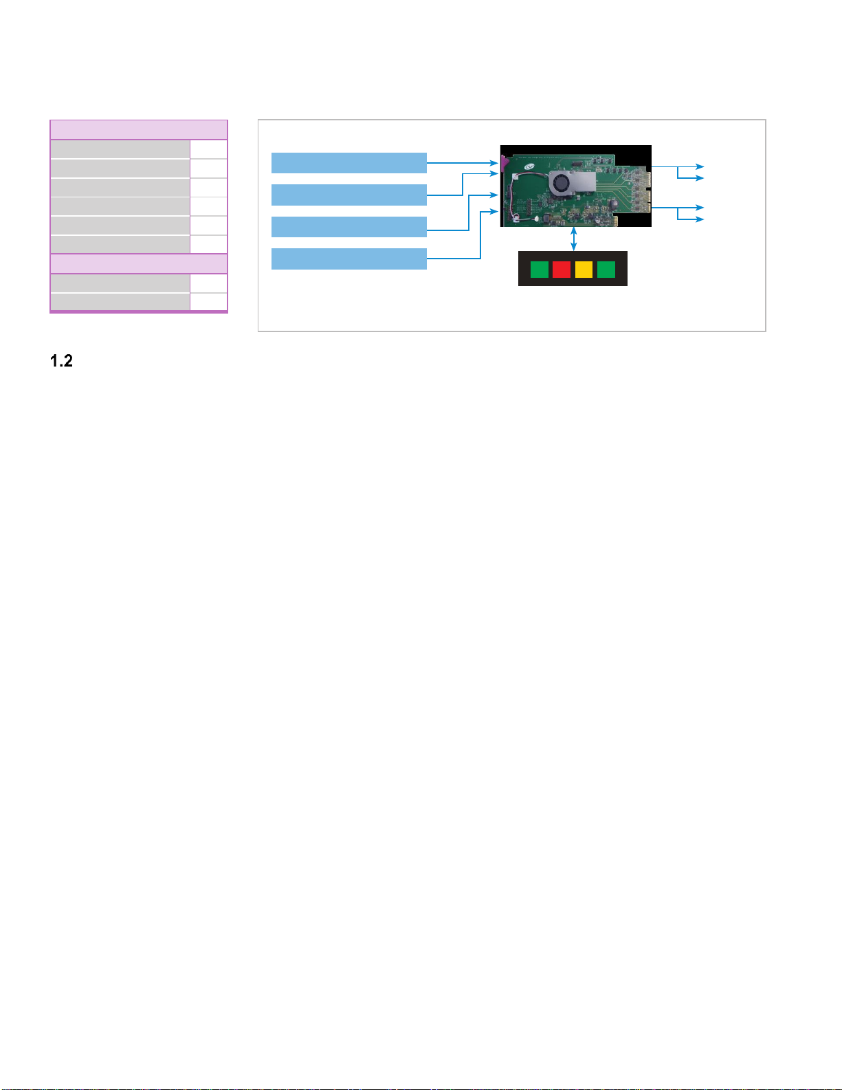
Features.............................................................................................................................................. 8
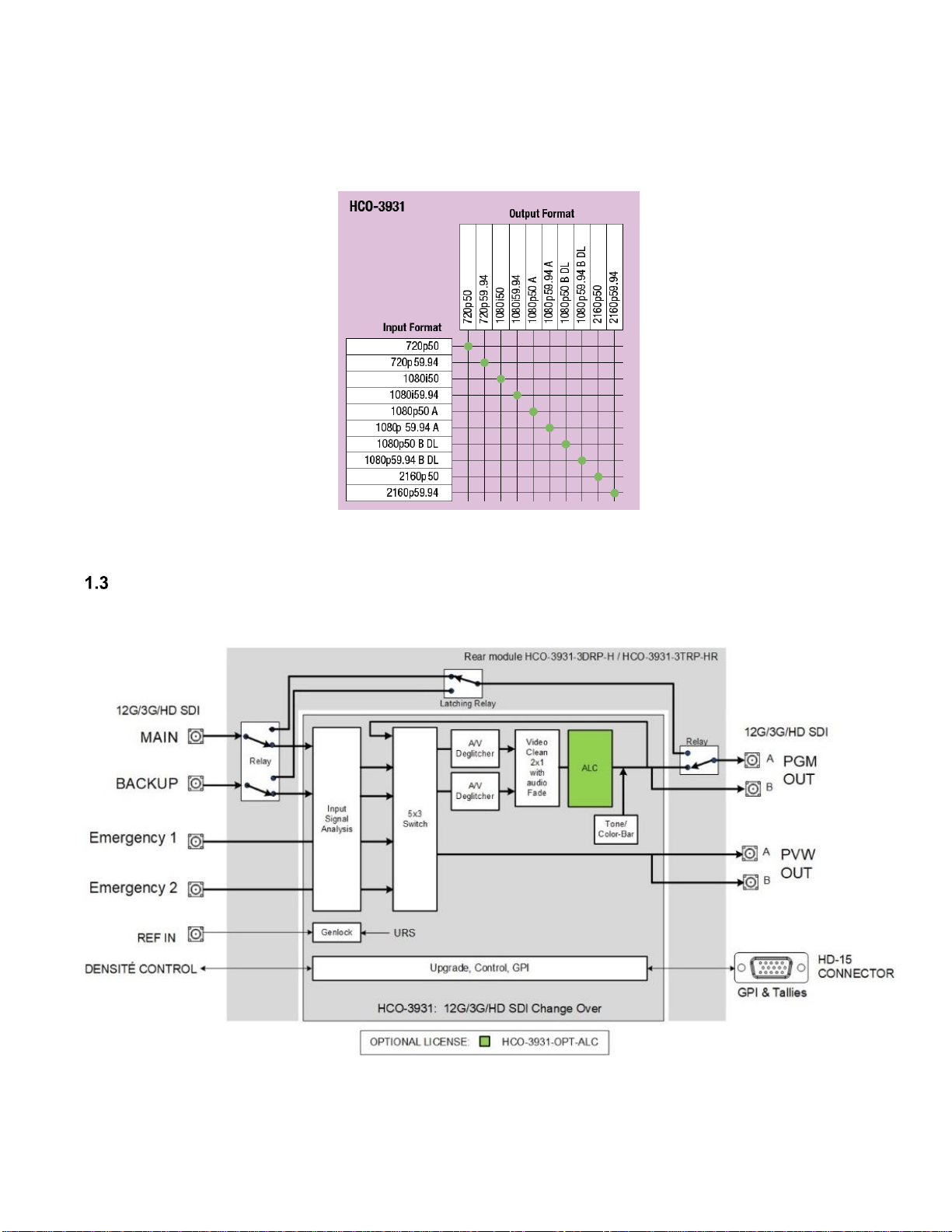
Block Diagram..................................................................................................................................... 9
Optional ALC License ....................................................................................................................... 10
Front Card-edge Interface................................................................................................................. 10
2Installation..............................................................................................................................11
Installing the Rear Connector Panel................................................................................................. 11
Installing the HCO-3931 Card........................................................................................................... 11
Rear Connector Panels..................................................................................................................... 12
2.3.1 Image of the Rear Connector Panel .................................................................................... 12
2.3.2 Summary of Rear Panel Connections ................................................................................. 13
2.3.3 Details of Rear Panel Connections...................................................................................... 14
3Operation................................................................................................................................17
Control options.................................................................................................................................. 17
Card-Edge Status LED ..................................................................................................................... 17
Local control using the Densité frame control panel......................................................................... 18
Remote control using iControl........................................................................................................... 19
3.4.1 The iControl graphic interface window................................................................................. 20
3.4.2 The Switch Control panel..................................................................................................... 22
3.4.3 The Probes Panel ................................................................................................................ 26
3.4.4 The Switch Configuration panel........................................................................................... 38
3.4.5 The Preview Configuration panel......................................................................................... 41
3.4.6 The Timing panel ................................................................................................................. 42
3.4.7 The Reference panel ........................................................................................................... 43
3.4.8 The ALC panel..................................................................................................................... 45
Test Panel......................................................................................................................................... 50
3.5.1 The Factory panel................................................................................................................ 52
Factory/Presets Panel....................................................................................................................... 52
3.6.1 User Presets ........................................................................................................................ 53
3.6.2 Load Factory button............................................................................................................. 54
3.6.3 Profiles................................................................................................................................. 54
Alarm Config Panel........................................................................................................................... 57
Information Panel.............................................................................................................................. 60
4Specifications.........................................................................................................................62
5Contact Us..............................................................................................................................64
Grass Valley Technical Support................................................................................................................. 64
Corporate Head Office............................................................................................................................... 64
ANNEX 1 –HCO-3931 User Interface..........................................................................................65

USER MANUAL
HCO-3931 | 7
1 HCO-3931 12G/3G/HD Change Over with Clean Switch and ALC
Introduction
The HCO-3931 from Grass Valley is a 4x1 12G/3G/HD SDI change-over that supports 16 channels of embedded
audio and metadata. The card can perform a video and audio “clean and quiet switch” between sources. In the event
of a power failure, the PGM signal is protected by a bypass circuit fitted on the rear panel, maintaining the integrity of
the selected MAIN or BACKUP signals at the output, and it is fully controllable via GPI. Two rear panels are available
with different bypass circuits, the HCO-3931-3DRP-H offers an active bypass that retains PGM signals for at least 48
hours while the HCO-3931-3TRP-HR uses 12G SDI rated bypass relays for extended protection.
At the core of the HCO-3931 versatility, a powerful automatic mode rules engine takes the guesswork out of
establishing which input will be routed to the outputs. By simply selecting which signal analysis probes to enable, con-
figuring the severity of each probe’s impact and optionally removing one or both Emergency inputs from the rules
engine’s consideration, you effectively instruct the card how to compute the relative health of each input based on its
weight and the probes statuses. This in turn enables you to effortlessly create a wide variety of failover mechanisms.
Change-over between inputs selection can also be performed manually, where any four sources can be selected from
the Densité controller, the iControl/GV Orbit software, or simply by using a GPI. A GPI can be connected to an
automation system or any simple GPI control panel. The GPI outputs give the status of the selected source, allowing
tallies to be triggered.
The HCO-3931 provides two 12G/3G/HD outputs: Program (PGM) and Preview (PVW). Each output is available on
two connectors (signal copy). The PVW output is user selectable to follow the main PGM output or any of four video
inputs.
Grass Valley’s next generation 16-channel automatic loudness control (ALC) option, HCO-3931-OPT-ALC, can
eliminate objectionable loudness variations between programs and commercials even better than with previous ALC
versions, thanks to the addition of an independent dynamic stage consisting of a fully configurable input compressor
and a new true peak output limiter with 1 ms buffer protection.
This new Densité card fully complements our line-up of 12G SDI products such as the HDA-3961 single/dual 12G DA
with optional fiber connectivity, MDX-3901 12G 16 audio channel AES/MADI embedder/de-embedder, XIP- 3901
SDI/IP agile processing platform and our other Grass Valley products.
Based on the proven Densité modular framework of over 100 cards, the flexible, space-efficient HCO-3931 is a 3 RU
card and is available with a two or three slots rear panel. With flexibility to configure up to 12 HCO-3931 change-over
cards per Densité 3+ FR4 frame with the two-slot rear panel, the Densité platform scales to a density of twelve 12G
SDI change-over cards in a 4 RU frame. This means space- and cost-efficient scaling for today and tomorrow.
The HCO-3931 is configured, controlled and monitored by GV Orbit from Grass Valley. It can also be configured and
controlled from iControl systems.
The HCO-3931 targets emerging needs to provide changeover with clean switch and optional Automatic Loudness
Control for single-stream 4K UHD signals using 12G SDI. The HCO-3931 is designed for a wide range of applications
where bullet-proof mission critical signal distribution is required for OB trucks, production studios and playout facilities
as shown here:

USER MANUAL
8| HCO-3931
Features
12G/3G/HD SDI input/output
Main, Backup and two Emergency inputs
On-Air Program and Preview outputs with two connectors each (signal copy)
Choice of external or frame URS reference input
Audio/video de-glitcher to handle video hot switch on every input
Clean and quiet switch function of video and 16 channels of audio on Program output
Optional 16-channel Automatic Loudness Control
GPIO –based inputs selection and tallies
Electronic switching with two rear panels that maintain selected input upon power loss for Primary Main and
Backup inputs:
oHCO-3931-3TRP-HR triple rear with relay backups
oHCO-3931-3DRP-H double rear with active bypass for a minimum of 48 hours of protection from a
power loss
Automatic change-over mode using internal signal analysis with configurable probes for all inputs
Manual change-over by local frame controller, iControl/GV Orbit or GPI
Alarm reporting to iControl/GV Orbit facility monitoring and control system
iControl and GV Orbit for configuration, control and monitoring
Main Channel
Backup Channel
Emergency Channel
Emergency Message
12G 12G
12G
GPI
12G
12G
12G
Key
1Key
2Key
3Key
4
Manual Bypass/Tally
PVW
On-Air
Bullet-proof On-air Protection
NoVideo 4
Video Reference Mismatch 4
Video Format Mismatch 4
Video Error 4
Black Detect 4
Freeze Detect 4
SilenceDetect (per channel) 4
AudioPresence (per group) 4
Configurable Probes
Video
Audio

USER MANUAL
HCO-3931 | 9
1.2.1 Supported Video Formats
The HCO-3931 supports the following video formats.
Figure 1
Supported Video Formats
Block Diagram
The following block diagrams show the functionality of the HCO-3931.
Figure 2
Functional Block Diagram - HCO-3931

USER MANUAL
10 | HCO-3931
Optional ALC License
16-channel on-board Audio Loudness Control (ALC) processing can be enabled with the HCO-3931-OPT-ALC
license.
Front Card-edge Interface
The front card-edge of the HCO-3931 incorporates two
elements:
Status LED (see section 3.2)
Select Button (see section 3.3)
Figure 3
Front card-edge layout
HCO-3931
Select
Status
Status LED
SELECT button

USER MANUAL
HCO-3931 | 11
2 Installation
Installing the Rear Connector Panel
Each Grass Valley Densité-series card is associated with a rear connector panel, which must be installed in the
Densité frame before the card can be inserted.
The HCO-3931 and its associated rear connector rear panel must be mounted in a Densité-3 or Densité-3+ series
frame. The following rear connector panels are available:
HCO-3931-3DRP-H: Double-width Densité-3 rear HD-BNC connectors. This active rear features electronic
latching bypass relays.
HCO-3931-3TRP-HR: Triple-width Densité-3 rear HD-BNC connectors. This passive rear features hardware-
based latching bypass relays.
See 2.3 - Rear Connector Panels on page 12 for for details about the signal connections available on this panel.
All cards and rear connector panels can be installed with the frame powered on. The card has connectors that plug
into a mid-frame motherboard to distribute power and connect to the controller card, as well as a second connector
that plugs directly into the rear connector panel for input and output.
To install the connector panel:
The rear connector panel must be installed with the card out of the frame.
1. If a card is installed in the slot for which the rear connector panel is being changed, it must be removed. Tilting
the swivel handle on the front of the card to lever the connectors apart, and then use the handle to pull the card
straight out of the slot.
2. Remove the existing rear connector panel (either blank or belonging to an existing card that is being changed)
by releasing the captive screw(s) at the bottom (Densité3+ or Densité-3+FR4) or on the side (Densité-3+FR1) of
the panel.
3. Position the new rear connector panel and secure it in place with the captive screw(s) at the bottom or on the
side.
Installing the HCO-3931 Card
Once a matching rear connector panel is in place, install the HCO-3931 card as follows:
1. Open the front panel of the frame.
2. Slide the HCO-3931card into the slot and push gently on the handle to seat the connectors.
When using a double-slot-width rear panel in a Densité-3+FR1 frame, the card should be inserted into the
lower of the two slots.
When using a double-slot-width rear panel in a Densité-3+FR4 frame, the card should be inserted into the
right-most of the two slots.
Inserting the card into the wrong slot will not damage the card, but the status LED on the card will flash red to
indicate that there is no connection to the rear panel.
3. Close the front panel of the frame.

USER MANUAL
12 | HCO-3931
Rear Connector Panels
2.3.1 Image of the Rear Connector Panel
The rear connector panel is shown below.
HCO-3931-3DRP-H –Double-width Densité-3 rear HD-
DIN connectors. This active rear features an electronic-
based latching bypass relay that provides 48 hours
minimum retention from a power failure for the PGM A
output signal with the MAIN or BACKUP input selection.
HCO-3931-3TRP-HR –Triple-width Densité-3 rear HD-
DIN connectors. This passive rear features a hardware-
based latching bypass relay that provides unlimited
retention from a power failure for the PGM A output
signal with the MAIN or BACKUP input selection.
Figure 4
HCO-3931 Rear Panels

USER MANUAL
HCO-3931 | 13
2.3.2 Summary of Rear Panel Connections
HCO-3931-3DRP-H
HCO-3931-3TRP-HR
Double-slot-width panel
Triple-slot-width panel
Hardware Bypass Latching Relay (unlimited retention)
Electronic Bypass Latching Relay (minimum 48 hour retention)
CONNECTORS
HD-BNC
HD-BNC
REF IN
12G/3G/HD IN
MAIN, BACKUP, EMERG 1, EMERG 2
12G/3G/HD OUT
PGM A, PGM B, PVW A, PVW B
CONNECTORS
HD15
HD15
GPIO

USER MANUAL
14 | HCO-3931
2.3.3 Details of Rear Panel Connections
12G/3G/HD IN –Serial Digital 12G/3G/HD input
Connect up to four serial digital video signals (MAIN, BACKUP and two emergency (EMERG 1 & EMERG 2) inputs),
conforming to the SMPTE ST 2082-10 standard for 12Gbps signals, SMPTE 292M standard for HD input signals, or
SMPTE-425M for 3Gbps signals, to the BNCs labeled 12G/3G/HD SDI IN. The HCO-3931 will automatically switch to
the detected line format.
MAIN: The main channel.
BACKUP: The backup channel.
EMERG 1: The emergency 1 channel.
EMERG 2: The emergency 2 channel.
OUT –Serial Digital Video Outputs
The HCO-3931 provides four 12G/3G/HD SDI video outputs, conforming to the SMPTE ST 2082-10 standard for
12Gbps signals, SMPTE 292M standard for HD input signals, or SMPTE-425M for 3Gbps signals to the BNCs labeled
12G/3G/HD SDI OUT.
PGM A, PGM B: The main on-air video output. A latching bypass relay maintains the PGM A output signal
with the MAIN or BACKUP input selection when there is a power failure.
PVW A, PVW B: The preview output is user selectable to follow:
oThe main PGM output.
oAny of the four video inputs.
oOr the current failover input to the main program output

USER MANUAL
HCO-3931 | 15
REF IN –Studio Reference Input
For external synchronization, connect a black studio reference signal to the BNC labeled REF IN.
Two reference signal formats are supported:
For 59.94 fps: 525 (SMPTE 170M / 318M NTSC black burst)
For 50 fps: 625 (ITU 624-4 PAL black burst)
GPIO Connector
The rear panels of the HCO-3931 include a GPIO interface that allows control of the switch process. When connecting
the HCO-3931 to an automation system, be aware of the following:
1. The HCO-3931 card senses the presence of an external power supply voltage on the GPIO input. Any voltage
greater than 1 V will silence the GPI Connector Power alarm, when this alarm is enabled.
2. GPIO inputs trigger on a momentary pulse. To be recognized without ambiguity, a GPIO trigger pulse should
have a duration of at least 50 ms.
Figure 5
GPIO input trigger pulse timing

USER MANUAL
16 | HCO-3931
The GPIO interface is implemented on an HD-15 connector. The pinout is as follows:
GPIO Label
Pin #
GPI-IN-MAIN
4
GPI-IN-BACKUP
9
GPI-IN-EMERGENCY1
3
GPI-IN-EMERGENCY2
8
GPI-IN-BYPASS
6
GPI-IN-AUTO
10
GPI-OUT-MAIN
1
GPI-OUT-BACKUP
7
GPI-OUT-EMERGENCY1
2
GPI-OUT-EMERGENCY2
12
GPI-OUT-BYPASS
11
GPI-OUT-AUTO
5
GPI-IN-PWR
15
GND
13,14
Note: You may find it convenient to purchase Grass Valley’s NSH15M HD15-to-terminal-block adapter, which
provides easy access to the GPIO pins.
Using the GPIO interface
Trigger the GPI-IN-MAIN, GPI-IN-BACKUP, GPI-IN-EMERGENCY1, or GPI-IN-EMERGENCY2 pin to select that
input.
Trigger the GPI-IN-AUTO or GPI-IN-BYPASS pin to select that mode.
Read the GPI-OUT- MAIN, GPI-OUT- BACKUP, GPI-OUT- EMERGENCY1, GPI-OUT- EMERGENCY2 pins to
identify which output is selected (“0” indicates selection).
Read the GPI-OUT-AUTO and GPI-OUT-BYPASS pins to determine whether either of these modes is in
operation (“0” indicates selection).
Note: When a GPIO input is triggered, the card switches to the input selected by the GPIO input. It may then change
operating mode, depending on the GPIO input selected, the card’s switch configuration (see 3.4.4 - The Switch
Configuration panel on page 38) and the card’s current operating mode (see 3.4.2 - The Switch Control panel on page
22).
Input
Card is in Auto mode
Card is in Bypass mode
GPI-IN-MAIN
Enter Manual Mode if so configured
GPI-IN-BACKUP
Enter Manual Mode if so configured
GPI-IN-EMERGENCY1
Enter Manual Mode if so configured or if this
input is excluded from the automatic rules
engine
Enter Manual mode
GPI-IN-EMERGENCY2
Enter Manual Mode if so configured or if this
input is excluded from the automatic rules
engine
Enter Manual mode

USER MANUAL
HCO-3931 | 17
3 Operation
Control options
The HCO-3931 can be controlled in different ways:
The local control panel and its push-buttons can be used to move through a menu of parameters and to adjust
parameter values (see section 3.3).
Grass Valley’s iControl system can be used to access the card’s operating parameters from a remote computer,
using a convenient graphical user interface (GUI). (see section 3.4)
Card-Edge Status LED
The status monitor LED is located on the front card-edge of the HCO-3931, and is visible through the front access
door of the DENSITÉ-3 frame. This multi-color LED indicates the status of the HCO-3931 by color, and by
flashing/steady illumination.
The chart shows how the various error conditions that can be flagged on the HCO-3931 affect the LED status.
If a cell is gray, the error condition cannot cause the LED to assume that status
If more than one LED status is possible for a particular error condition, the status is configurable.
See Section 3.7 - Alarm Config Panel on page 57for details.
The factory default status is shown by a
The LED will always show the most severe detected error status that it is configured to display, and in the chart error
severity increases from left to right, with green representing no error/disabled, and flashing red the most severe error.
LED Status
Error Condition
Green
Yellow
Red
Flashing
Red
No errors
No Video
Video error
Format Mismatch
Reference Mismatch
Input timing out of range
Black detection
Freeze detection
Audio presence group
Audio silence channel
SDI input used as reference
Ext Reference Presence
URS 29.97 Hz Presence
URS 25 Hz Presence
Reference Unlocked
MAIN not on Program
MAIN Impaired
BACKUP not on Program

USER MANUAL
18 | HCO-3931
LED Status
Error Condition
Green
Yellow
Red
Flashing
Red
BACKUP Impaired
EMERGENCY1 not on Program
EMERGENCY1 impaired
EMERGENCY2 not on Program
EMERGENCY2 impaired
FPGA Engine Stopped
Hardware Failure
Rear Detection
Card Fan
Card Overheat
GPIO Connector Power
If the LED is Flashing Yellow, it means that the card is selected for local control using the Densité frame’s control
panel. See Section 3.3 for details.
Local control using the Densité frame control panel
There are two types of local control panel:
Panel type
Frame models
Appearance
Physical
Densité-2, Densité-3, Densité-
3+FR1,
Touch screen
Densité 3+FR4
The local control panel is fastened to the front of the controller card.
The physical panel is accessed by opening the front door of the frame.
The touch screen panel is accessed through an aperture in the frame door.
The panel consists of a display capable of displaying two lines of text, each 16 characters in length, and four
pushbuttons. The functionality of the pushbuttons is as follows:
[+] [–] Used for menu navigation and value modification

USER MANUAL
HCO-3931 | 19
[SEL] Gives access to the next menu level. When a parameter value is shown, pushing this button once
enables modification of the value using the [+] and [–] buttons; a second push confirms the new value
[ESC] Cancels the effect of parameter value changes that have not been confirmed; pushing [ESC] causes the
parameter to revert to its former value.
Pushing [ESC] moves the user back up to the previous menu level. At the main menu, [ESC] does not
exit the menu system. To exit, re-push the [SEL] button for the card being controlled.
If no controls are operated for 30 seconds, the controller reverts to its normal standby status, and the selected card’s
STATUS reverts to its normal operating mode.
To assign the local control panel to the HCO-3931:
Physical Panel: Push the SELECT button on the HCO-3931 card edge (see Section 1.5).
Touch-screen panel: In the home screen, touch the virtual button corresponding to this HCO-3931.
The STATUS LED on the HCO-3931 flashes yellow, and the touch-screen status shows yellow for the HCO-3931.
Use the control panel buttons to navigate through the menu, as described above.
The complete menu structure is shown in ANNEX –HCO-3931 User Interface, beginning on page 65.
Remote control using iControl
The operation of the HCO-3931 may be controlled using Grass Valley’s iControl system.
This manual describes the control panels associated with the HCO-3931 and their use.
Please consult the iControl User’s Guide for information about setting up and operating iControl.
In iControl Navigator or iControl Websites, double-click on the HCO-3931 icon to open the control panel.

USER MANUAL
20 | HCO-3931
3.4.1 The iControl graphic interface window
The basic window structure for the HCO-3931 is shown in Figure 6. The window identification line gives the card type
(HCO-3931) and the slot number where the card installed in its Densité frame.
There are four main sections in the window itself, identified in Figure 6:
1. The Status Icon area shows a series of seven icons that
report the status of some card parameters. Figure 7 shows
the various forms that may appear; their meaning is described
below.
Icon 1 –Control status
A: Green - Remote Control through iControl
B: Yellow - Local control using the menu
Icon 2 –Reference status
A: Green - Locked to external reference
B: Red - Reference is missing
C: Grey - Using an SDI input as Reference
Icon 3 –Input MAIN status
A: Green - Status OK
B: Red –Error
C: Grey –No analysis performed
Figure 6 HCO-3931 iControl graphic interface window
1
2
3
4
Figure 7 Status Icons
A
B
C
1 2 3 4 5 6 7 8
Table of contents
Other GRASS VALLEY Control Unit manuals

GRASS VALLEY
GRASS VALLEY 8964DEC - User manual

GRASS VALLEY
GRASS VALLEY KAMELEON Series User manual

GRASS VALLEY
GRASS VALLEY KAMELEON Series User manual

GRASS VALLEY
GRASS VALLEY 8990ARC - User manual

GRASS VALLEY
GRASS VALLEY KAMELEON Series User manual

GRASS VALLEY
GRASS VALLEY KAMELEON Series User manual

GRASS VALLEY
GRASS VALLEY KAMELEON Series User manual

GRASS VALLEY
GRASS VALLEY 8949MDA-CFR User manual

GRASS VALLEY
GRASS VALLEY KAMELEON Series User manual

GRASS VALLEY
GRASS VALLEY KAMELEON Series User manual