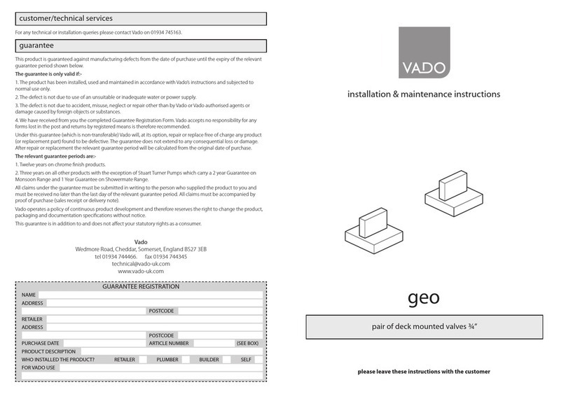
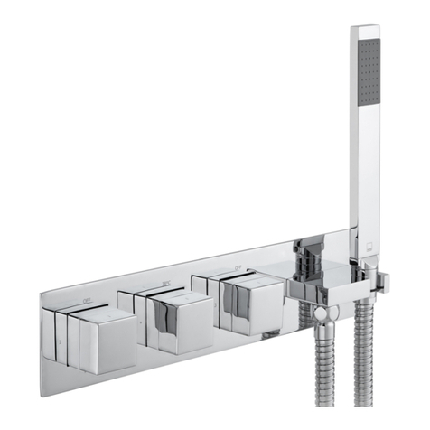
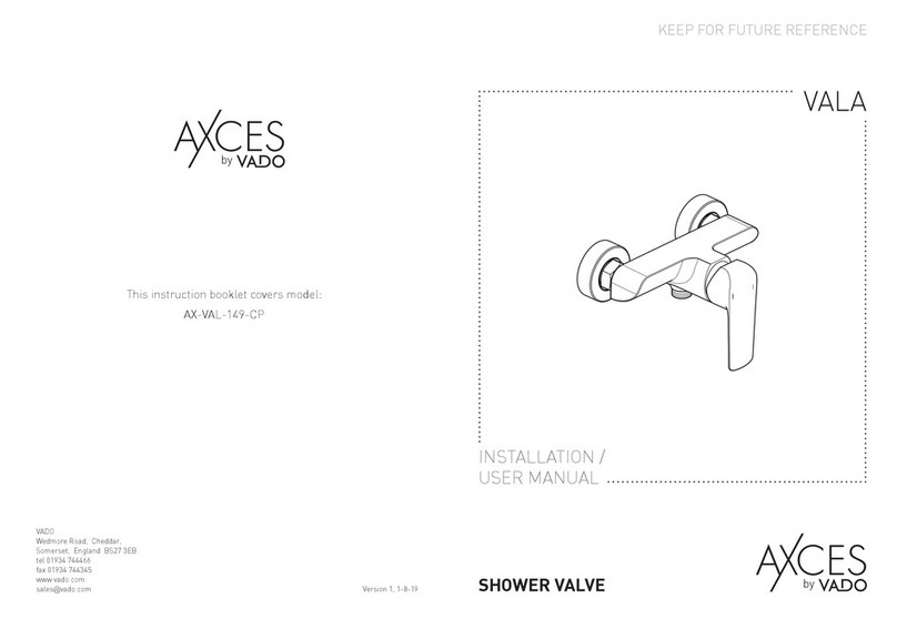
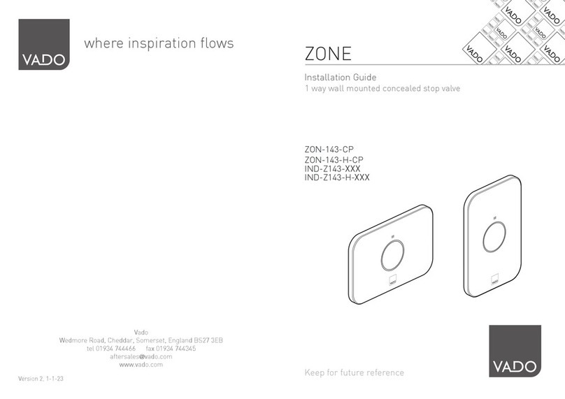
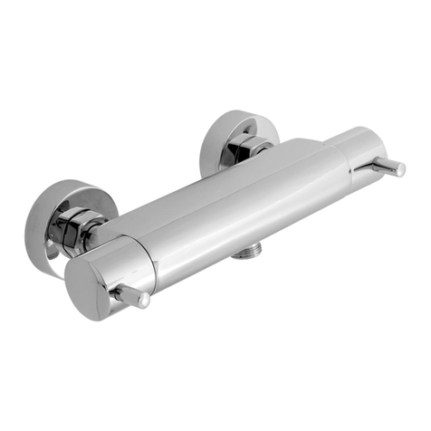
VADO AXCES SIRKEL AX-SIR-149T-CP Instruction Manual

KEEP FOR FUTURE REFERENCE
INSTALLATION /
USER MANUAL
This instruction booklet covers model:
AX-SIR-149T-CP
Version 1, 1-8-19
VADO
Wedmore Road, Cheddar,
Somerset, England BS27 3EB
tel 01934 744466
fax 01934 744345
www.vado.com
sales@vado.com
1 OUTLET THERMOSTATIC
SHOWER VALVE
SIRKEL

23
Please read these instructions carefully before starting installation and keep for
future reference.
Remove all packaging and check the product for missing parts or damage before
starting installation.
Any alterations made to this product and fittings may infringe water regulations and
will invalidate the guarantee.
The installation must comply with all Local/National Water Supply Authority
Regulations/Byelaws and Building and Plumbing Regulations.
To be installed in accordance with BS EN806.
We strongly recommend that you use a qualified and registered plumber.
General installation
Important - please read
This fitting is a mixing device and therefore water supplies should be reasonably
balanced.
When installed, the fitting must comply with the requirements of the Water Supply
(Water Fittings) Regulations 1999 and Scottish Byelaws 2004.
For further information, contact the Water Regulations department of your local water
supplier (see the WRAS website www.wras.co.uk for details) or the Water Regulations
Advisory Scheme by email (info@wras.co.uk) or telephone: 01495848454.
Before making any inlet pipe connections, all supply pipes MUST be thoroughly flushed
to remove debris. Failure to do so could result in damage or low flow from the mixer
unit. Water Supply (Water Fittings) Regulations 1999 Schedule 2 Section 13.
The fitting of isolating valves to the inlet feeds is advised for ease of maintenance.
Please take great care when installing this mixer not to damage its surface.
Please note if installing in an enclosed environment, access should be left for servicing
and maintenance. No costs relating to inadequate access can be accepted.
Operating Specifications
Operating Pressure
Minimum operating pressure 1 bar
Maximum operating pressure 5 bar
Contents of Packaging
Installation guide &
User manual
Shrouds x 2
KEEP FOR FUTURE REFERENCE
INSTALLATION /
USER MANUAL
1 OUTLET THERMOSTATIC
SHOWER VALVE
SIRKEL
Accessory box 1
Valve
Offset connecters x 2

4 5
Dimensions
278mm
50mm
150mm
69mm
Ø55mm
½"
Installation
Before installing your new mixer, flush through the pipe work to ensure removal of
debris, turn off the water supply.
Prepare the wall with 2 flush ½” connecters at 150mm centres. Connect the
water supply to the inlet pipes. The hot water should be connected to the left hand
connecter and cold to the right.
Note: The valve must be connected to rigid pipe work for support.
Using PTFE tape screw the offset connecters to the wall fittings followed by
the shrouds.
Screw the locking nuts of the valve onto the connecters, some adjustment can be
made to the offset connecters to align the centres and level up the valve.
Attach the shower hose to the outlet at the bottom of the valve.
Locking nuts
Cold
Hot
Offset connecters
½” connecters
150mm
Locking nuts
Shrouds
Shower hose
connection

6 7
Operation
Moving the handle will
increase/decrease the
water temperature.
Turning the handle away
from the user will start
the flow of water.
Hot
Cold
Pushing down on this
button will override
the set temperature.
Cleaning instructions
The electroplating on this product is finished to the highest standard. Due care needs
to be taken to ensure the appearance is retained.
We recommend cleaning all products with a soft damp cloth ONLY and advise strongly
against the use of all aggressive/corrosive cleaning products i.e. powders and liquids.
If these instructions are not followed, this may invalidate your guarantee in the event
of a problem occurring.
Off
On

89
Commissioning
The valve has been factory set under balanced pressures and hot water supply at 65°C.
When your specific operating conditions are significantly different from the above, the
temperature of the water may vary from the setting.
When the difference is too great, you can adjust the calibration of the valve to suit
individual requirements of the installation:
1. Check the temperature of the water being delivered from the outlet with a
thermometer.
Note: temperature readings should be taken at normal flow rate after allowing for the
system to stabilise.
2. If the temperature is not 38°C (When the 38º is aligned with the override button)
proceed to reset the calibration as follows.
Remove the handle: Prise out the cover, remove the screw and washer and pull off
the handle.
Ensure the step on the stop ring is located at 12 o'clock.
Do not remove the plastic stop ring. Turn the spline of the thermostatic valve clockwise
to decrease the temperature and anti-clockwise to increase the temperature until 38°C
is achieved at outlet.
Note: the sensing part of the thermometer probe must be fully submerged in the water
that is to be tested.
Replace the handle making sure that the pin is against the step.
Once the handle has been attached ensure the temperature does not exceed 46°C when
turned entirely anti-clockwise.
Your valve setting is now commissioned.
Cover
Screw
Stop ring
Pin
Inside handle
Handle
Override
button
Valve splines
Step
Maintenance
We advise that the below is carried out annually as failure to do so may result in
invalidation of warranty.
Isolating the thermostatic valve
IMPORTANT: Please see the below procedure for isolating the thermostatic valve.
1. Isolate the incoming hot and cold water to the valve.
2. Turn shower valve on (left handle) to check isolation, please ensure that your body/
hands are not under the flow of water as there is a potential for delivery of hot water.
3. Remove temperature control handle and temperature stop ring (essential).
4. With shower in the on position, replace temperature handle on thermostatic Valve
(ensure temp stop has been removed).
5. Turn temp handle fully anti clockwise until stop point is reached and can be turned no
further , please ensure that your body/hands are not under the flow of water as there is
potential for delivery of hot water if isolation has been unsuccessful.
6. Turn temperature handle fully clockwise until resistance is felt.
7. If there is no flow of water coming from the outlet during both points 5 and 6 isolation
has been successful, you may now remove and maintain the cartridge.
8. If at any of the above point’s water continues to flow please isolate at an alternative
point within the system for both hot and cold and repeat points 2-8.
Filters
This thermostatic valve is fitted with a double filtering facility.
Filters are fitted on the water inlets and on the thermostatic cartridge.
Depending on the water quality, filters may become dirty,
causing reduced flow and inefficient working of the valve.
Inlet lters
Check water has been isolated. Undo both locking nuts at the back of the valve and
remove from the wall. Pull out the filter/washer, rinse in water to remove the dirt, and
then soak them in vinegar or descaling agent.
Thermostatic cartridge
To clean the filters, you must first remove the cartridge from the housing.
Removing the Cartridge:
1. Check water has been isolated.
2. Remove the stop ring
3. Using a suitable spanner remove the thermostatic cartridge.
4. Clean filters by rinsing them under running water to remove any debris.
5. If there is limescale deposits then it is recommended to immerse the cartridge for a
few minutes in 50% white vinegar + 50% hot water, brush the filters gently and then rinse
under running water to clean all particles. If this is not effective, a replacement cartridge
should be fitted.
10
Maintenance
Cover
Screw
Stop ring
Pin
Inside handle
Handle
Override
button
Valve splines
Step
11
Guarantee
All AXCES by VADO products come with a 2 year guarantee as standard. Within this
guarantee period VADO will provide replacement parts and any labour [SEE NOTE 1,
GUARANTEE CONDITIONS] needed to complete the product repair.
This standard guarantee may be extended by registering your product to give a 10 year
guarantee (2 years parts and labour plus 8 years on parts supply only.).
Operational components such as, but not limited to; thermostatic cartridges, diverters,
headworks and flow control, waste mechanisms, shower hoses, O-rings and seals are
guaranteed for 2 years parts and labour plus 3 years on parts supply only.
Guarantee Conditions
Our products are guaranteed against manufacturing defects from the date of purchase until
the expiry of the relevant guarantee period shown above.
The guarantee is only valid if:
•The product has been installed, used and maintained in accordance with VADO's
instructions and subjected to normal use only.
•The defect is not due to use of an unsuitable or inadequate water or power supply.
•The defect is not due to accident, misuse, neglect or incorrect/inappropriate repair (other
than by VADO or VADO authorised agents) or damage caused by foreign objects
or substances.
•The extended guarantee is only available if you have completed the Guarantee Registration
Process. This can be done via the VADO website or via phone to our aftersales team.
Registration must be completed within 6 months from date of purchase.
Under the extended guarantee period VADO will, at its option, offer to supply any
replacement product (or component part) assessed to be defective [SEE NOTE 2].
The guarantee (whether standard or extended) is non-transferable to any subsequent owner.
All claims under the guarantee should be notified in the first instance to our Aftersales
department, contact details below, this must be done no later than the last day of the
relevant guarantee period. All claims must be accompanied by proof of purchase (sales
receipt or delivery note) from an official AXCES by VADO dealer.
The guarantee does not extend to any consequential loss or damage.
After repair or replacement, the relevant guarantee period will be calculated from the
original date of purchase.
VADO operates a policy of continuous product development and therefore reserves the right
to change the product, packaging and documentation specifications without notice.
NOTES:
[1] Labour via our engineer network is only available in the UK. Attendance by a VADO
engineer or sub-contract engineer will be under our standard terms and conditions.
[2] VADO reserves the right to charge in advance for a product (or replacement part) pending
collection and investigation (at VADO expense) to confirm a defect is due to a manufacturing
issue. If a defect is found the charge will be refunded or cancelled.
This guarantee is in addition to and does not affect your statutory rights as a consumer.
Tel: 01934 745163
Email: aftersales@vado.com
6. Before reassembling the cartridge, clean its housing with a wet cloth and grease the
‘O’ rings using a suitable silicone grease.
7. Reassemble the cartridge into the body, then place the plastic stop ring onto the
cartridge with the step at the 12 o’clock position.
8. Turn on the water supply.
9. Check the water temperature to ensure correct commissioning.
See page 8 of this guide for commissioning.
10. Ensure that the step on the stop ring is at 12 o’clock and replace the handle with
the temperature override button also pointing at 12 o’clock being careful not to turn the
spline of the valve.
Table of contents
Other VADO Control Unit manuals

VADO
VADO celsius Installation and operating instructions

VADO
VADO ALTITUDE User manual

VADO
VADO geo Installation and operating instructions

VADO
VADO AX-EKO-145-CP Instruction Manual

VADO
VADO NOTION TAB-128/3WO-NOT-CP User manual

VADO
VADO IND-Z143 Series User manual

VADO
VADO Axces AX-VAL-149-CP Instruction Manual
Popular Control Unit manuals by other brands

Kallista
Kallista P29508 installation guide

CLA-VAL
CLA-VAL 750B-4KG1 Installation operation & maintenance

Boundary Devices
Boundary Devices Nitrogen series user manual

Azbil
Azbil ACTIVAL VY519 J Series Specifications & instructions

ITRON
ITRON OpenWay Riva 500G ERT installation guide

My ADT
My ADT TSSC quick guide