45
Triode mit modernster Schaltungstechnik kombiniert.
Ziel der Entwicklung war, die besonderen Übertra-
gungseigenschaften einer Röhre zu nutzen, und das
hiermit verstärkte Kapselsignal kontrolliert, unver-
fälscht und rückwirkungsfrei an den Mikrophonaus-
gang zu bringen. Daher wird der bei Röhrenmikro-
phonen übliche Ausgangsübertrager nicht verwendet.
Statt dessen wird zum Treiben der unterschiedlichen
Ausgangslasten ein besonders für Audiosignale geeig-
neter integrierter Verstärker mit sehr geringen Ver-
zerrungen, sehr kleiner Rauschspannung und hoher
Stromkapazität eingesetzt. So ist die Röhre völlig vom
Mikrophonausgang entkoppelt und wird mit ihrer
typischen Kennlinie bis zu sehr hohen Pegeln für die
Eingangssignalaufbereitung nutzbar. Im Gegensatz zu
herkömmlichen Röhrenmikrophonen sind aufgrund
der hohen Ausgangsstromkapazität Kabellängen bis
zu insgesamt 300 m erlaubt, ohne Einbußen in der
Signalqualität in Kauf nehmen zu müssen.
Die Röhre verstärkt die Kapselspannung um ca. 10 dB
und schließt Resteinflüsse der nachgeschalteten Elek-
tronik auf die Signalübertragung des Mikrophons
gänzlich aus. Dennoch wird ein sehr hoher Dynamik-
umfang bewältigt, da eine Spitzenausgangsleistung
von ± 10 V bei 20 mA zur Verfügung steht.
Der ideale Arbeitspunkt der Röhre wird während der
gesamten Lebensdauer stabilisiert. Das betrifft sowohl
den Anodenstrom als auch die Heizspannung, die
über einen Regelkreis im Netzgerät konstant gehal-
ten wird. Im Mikrophonkabel entstehende Span-
nungsabfälle bis zu 4 V = – das entspricht ca. 100 m
Kabel zwischen Mikrophon und Netzgerät – werden
durch eine Sensorleitung erfaßt und ausgeglichen.
Auch eine Störung dieser Leitung durch Kurzschluß
oder Unterbrechung ist ungefährlich, da für diesen
Fall eine Absenkung der Heizspannung und eine Ab-
schaltung aller weiteren Betriebsspannungen erfolgt.
Das Aufheizen der Röhre erfolgt in Hinblick auf eine
lange Lebensdauer schonend über eine rückläufige
Strombegrenzung.
Die für das Mikrophon benötigten Betriebsspannun-
gen werden aus dem Universal-Netzgerät N 149 A
unter Benutzung eines Schaltspannungsreglers ge-
wonnen. Eine analoge Vorregelung und doppelstufi-
ge aktive Filterung am Ausgang des Schaltreglers sor-
gen für Betriebsspannungen hoher Qualität mit sehr
geringen überlagerten Störspannungen.
Der NF-Ausgang des Netzgerätes ist mit besonderen
Schutzmaßnahmen versehen, die einen Betrieb des
Mikrophons ohne jegliche Einschränkung an mit 48 V-
Phantomspeisung belegten Modulationsdosen ermög-
lichen. Hierbei wird die Phantomspeisung mit ca.
1 mA belastet.
2.2 Inbetriebnahme
Das M 147 Tube wird als Set zusammen mit dem
8-adrigen Mikrophonkabel KT 8, dem Netzgerät
N 149 A und dem Stativgelenk SG 1 in einem Alu-
minium-Koffer geliefert. Das Stativgelenk SG 1 besitzt
ein 5/8"-27-Gang Innengewinde mit einem Reduzier-
stück für 1/2"- und 3/8"-Gewinde.
Zum Schutz der Mikrophonkapsel ist ein Textil-
Staubschutz beigefügt. Wird das Mikrophon längere
Zeit nicht benutzt, sorgt dieser für einen luftdurchläs-
sigen, effektiven Schutz vor Verschmutzung.
Zur Inbetriebnahme des Mikrophones ist die Reihen-
folge des Anschließens der Kabel unerheblich. Eine
Sensorik im Netzgerät sorgt dafür, daß die Betriebs-
spannungen erst bei funktionstüchtigem Anschluß des
Mikrophones hochgefahren werden. Die LED im
Netzgerät wechselt dann vom Glimmzustand auf ein
helles Leuchten über.
Nach spätestens einigen Minuten hat die Röhre im
M 147 Tube ihren stabilen Betriebszustand erreicht
und weist dann ihren besonders niedrigen Eigenge-
räuschpegel auf.
Eine eventuell anliegende externe Phantomspeisung
beeinträchtigt die Funktion des M 147 Tube nicht.
Wird eine externe Phantomspeisung an- oder abge-
schaltet, ergibt sich kurzzeitig ein leicht erhöhter Ei-
gengeräuschpegel.
Der Netzschalter des N 149 A unterbricht die Zulei-
tungen des eingebauten Netzteiles sekundärseitig.
Zur Stromersparnis sollte das N 149 A bei längerer
Nichtbenutzung vom Stromnetz getrennt werden.
Das M 147 Tube darf nur mit den Neumann-
Speisegeräten N 149, N 149 A oder N 149 V be-
trieben werden.
Abhängig vom Anwendungsfall werden folgende Zu-
behörteile zur Verbesserung der Signalqualität und
zum Schutz des Mikrophones vor Verschmutzung
empfohlen:
• Elastische Aufhängung EA 1
• Windschutz WS 87
• Popschutz PS 10 und PS 20.
Nähere Angaben dazu im Kapitel „Zubehör“.
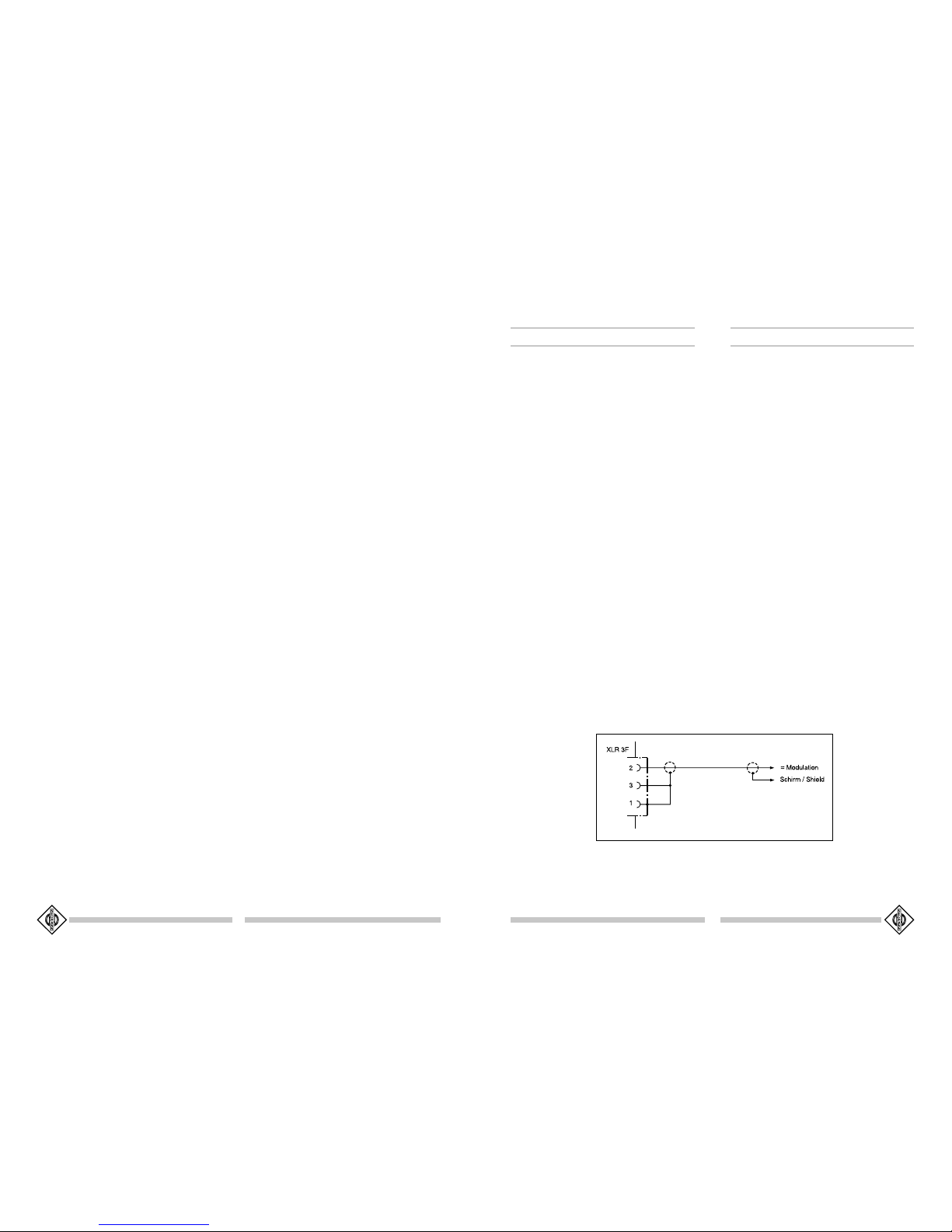
2.3 Ausführungsform und Beschaltung des
Mikrophon- und Netzgeräteausgangs
Das Mikrophon hat eine nickelmatte Oberfläche. Der
8-polige Stecker des Mikrophons und des Netzgerä-
tes ist folgendermaßen beschaltet:
ed triode and state-of-the-art circuitry. The develop-
ers‘ aim was both to utilize the advantageous prop-
erties of a vacuum tube for amplifying the capsule sig-
nal and to exclude any interference from other parts
of the circuitry when the amplified signal is fed to the
microphone output. This is why the M 147 Tube –
unlike conventional tube microphones – does not
use an output transformer but an integrated amplifi-
er to drive the different output loads. This special
audio amplifier features an extremely low THD, low
self-noise and high current capacity. Thus, the vacu-
um tube is entirely decoupled from the microphone
output, and the typical tube characteristic can be
used for processing highest input signal levels. In con-
trast to conventional tube microphones the high out-
put current of the M 147 Tube allows cable lengths
of up to 300 m without risking a deterioration of sig-
nal quality.
The tube amplifies the capsule voltage by about 10 dB
to exclude any remaining impact of the electronics on
the microphone signal. Despite this amplification the
dynamic range of the M 147 Tube remains very wide
as the microphone delivers a peak output voltage of
± 10 V at 20 mA.
During its entire life, the operating point of the tube is
kept stable. This refers both to the anode current and
to the heater voltage which is stabilized by a control
loop in the power supply unit. Cable losses of up to
4 V DC –which corresponds to a cable length of ap-
prox. 100 m between the microphone and the power
supply unit – are detected and compensated for by a
sensor line. A breakdown of this line due to a short-
circuit or an open circuit is not dangerous as the
heater voltage would automatically be reduced and all
other voltages switched off. To ensure a long life, the
tube is heated very gently by current limiting with fold-
back characteristic.
The operating voltages for the M 147 Tube are de-
livered by the power supply unit N 149 A using a
switching regulator. Analog pre-controlling and two-
stage active filtering at the switching regulator‘s out-
put ensure high quality operating voltages with a min-
imum of unwanted interfering voltages.
The signal output of the power supply unit is provid-
ed with special protective circuitry so that the micro-
phone can be connected to audio inputs with 48 V
phantom powering without any problems. The load
on the phantom power source will be approx. 1 mA.
2.2 Getting Started
The M 147 Tube comes complete with KT 8 eight-
core microphone cable, N 149 A power supply unit,
SG 1 swivel mount and an aluminium case. The stand
connector of the SG 1 swivel mount has a 5/8"-27 in-
ternal (female) thread and comes complete with an
adaptor to convert to 1/2" and 3/8" threads.
A cloth dustcover is included to protect the micro-
phone capsule. This provides breathable, effective
protection against contamination if the microphone
goes unused for long periods.
When hooking up the microphone, the order in
which the cables are connected does not matter. A
sensor in the power supply ensures that the operat-
ing voltages are not run up until the microphone is
connected properly. The LED on the power supply
then changes from a low glow to shine brightly.
Within a few minutes, at the latest, the tube in the
M 147 Tube reaches its stable operating condition
and then evidences its particularly low residual noise
level.
External phantom power, if present, does not detract
from the performance of the M 147 Tube. If an ex-
ternal phantom power source is switched on or off,
only a short, slight rise in the residual noise level will
result.
The on/off switch of the N 149 A functions as a sec-
ondary voltage interrupt for the feeds from the built-
in mains unit. To save energy, the N 149 A should be
unplugged from the wall outlet if it is not in opera-
tion for an extended period.
The M 147 Tube must only be operated with the
Neumann power supplies N 149, N 149 A or
N 149 V.
Depending on the application in question, we rec-
ommend using the following accessories to enhance
signal quality and protect the microphone from con-
tamination:
• EA 1 Elastic Suspension
• WS 87 Windscreen
• PS 10 and PS 20 Popscreen.
For details, see the topic "Accessories".
2.3 Type and Configuration of the
Microphone and Power Supply Outputs
The microphone is finished in matt nickel. The 8-pin
connector of the microphone and the corresponding
connector of the power supply unit have the follow-
ing configuration: