45
The entire exposed surface of the capsule, including
the membranes, is at ground potential making it im-
mune to electric as well as atmospheric conditions
and dirt. In order to protect the capsule from me-
chanical shock transmission it is elastically suspended.
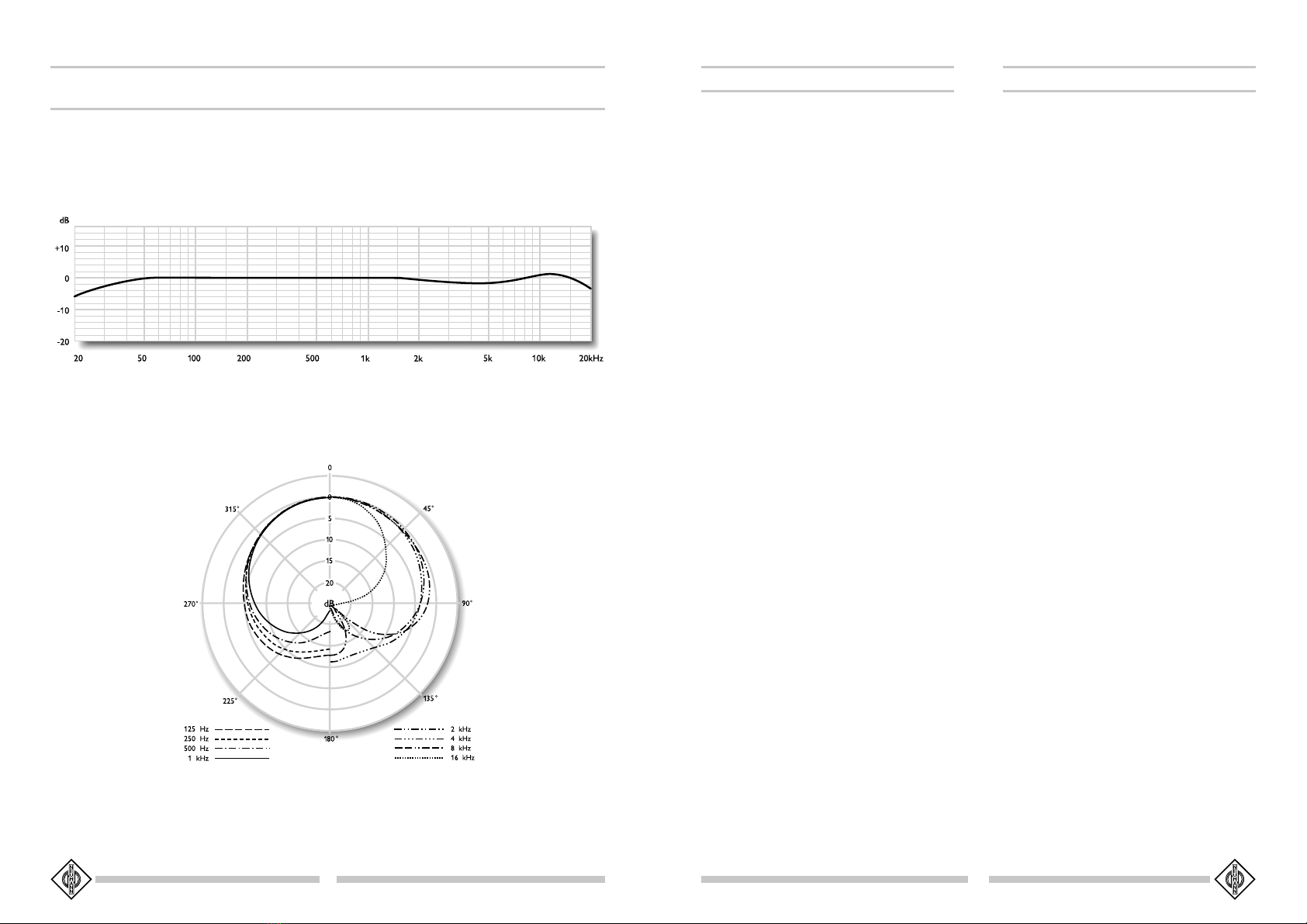
As the TLM 193's amplifier is linear up to 20 Hz, ex-
tremely low frequency signals can be transmitted with-
out distortion as well. On the other hand the micro-
phone is therefore more sensitive to low-frequency
noises as structure-borne or wind and pop disturbanc-
es. For specific applications it is therefore recommend-
able to use protective accessories as the EA 1 (mt)
elastic suspension, the PS 15 or PS 20 a pop screens
or the WS 89 windscreen (see section 7).
2.1 Microphone Versions and
Output Wiring
The following versions of the TLM 193 microphone
are available:
TLM 193TLM 193
TLM 193TLM 193
TLM 193 ............................ blk .............................. Cat. No. 08381
Version with 3-pin XLR connector insert and matte
black finish. Requires XLR 3 F female connector.
Microphone wired as per IEC 60 268-12 or DIN EN
60 268-12:
Modulation is connected to pins 2 and 3; the shield
is connected to pin 1.
A sudden sound pressure rise in front of the front
diaphragm causes a positive voltage to appear at pin 2.
2.3 Microphone Cables
The following cables are available for the TLM 193
microphone:
IC 3 mtIC 3 mt
IC 3 mtIC 3 mt
IC 3 mt ................................. blk .............................. Cat. No. 06543
10 m microphone cable, 5 mm in diameter, with dou-
ble twist (double helix) braiding as shield. 3-pin XLR
connectors, matte black. For feeding the audio signal
to mixing consoles, etc.
ICIC
ICIC
IC 44
44
4 (10 m) ........................ ni ................................ Cat. No. 06547
ICIC
ICIC
IC 44
44
4 mt (10 m) ................ blk .............................. Cat. No. 06557
10 m microphone cable, 5 mm in diameter, with dou-
ble twist braiding as shield. 3-pin XLR connectors and
SGCD 3 (mt) rotatable swivel mount. It has a 5/8"-
27 female thread that can be fastened to tripods. A
threaded adapter for 1/2"- and 3/8" studs is included.
Designed for microphones with a threaded connec-
tion.
Die gesamte Oberfläche der Kapsel einschließlich der
Membranen liegt auf Massepotential und ist daher un-
empfindlich gegen elektrische und atmosphärische Ein-
flüsse und gegen Schmutz. Die Kapsel ist zum Schutz
gegen Körperschallübertragung elastisch gelagert.
Da der Verstärker des TLM 193 bis 20 Hz linear ver-
läuft, können auch extrem niederfrequente Signale
unverfälscht übertragen werden. Andererseits ist das
Mikrophon dadurch empfindlicher für tieffrequente Stö-
rungen wie Körperschall oder Pop- und Windgeräu-
sche. Daher empfiehlt sich eventuell die Verwendung
der Elastischen Aufhängung EA 1 (mt), des Popschirms
PS 15 oder PS 20 a oder des Windschutzes WS 89
(siehe Kapitel 7).
2.1 Ausführungsformen und Beschaltung des
Mikrophonausgangs
Das Mikrophon kann in folgenden Ausführungsformen
geliefert werden:
TLM 193TLM 193
TLM 193TLM 193
TLM 193 .............................. sw ............................. Best.-Nr. 08381
Ausführung mit 3-poligem XLR-Steckverbinder und
schwarzmatter Oberfläche. Erforderliches Gegenstück:
XLR 3 F.
Die Zuordnung der Mikrophonanschlüsse entspricht
DIN EN 60 268-12 bzw. IEC 60 268-12:
Die Modulationsadern liegen an Pin 2 und 3, die Ab-
schirmung an Pin 1.
Bei einem Schalldruckanstieg vor der vorderen Mikro-
phonmembran tritt an Pin 2 eine positive Spannung auf.
2.3 Mikrophonkabel
Für das TLM 193 stehen folgende Kabel zur Verfü-
gung:
IC 3 mtIC 3 mt
IC 3 mtIC 3 mt
IC 3 mt ................................. sw ............................. Best.-Nr. 06543
10 m langes Mikrophonkabel, Durchmesser 5 mm, mit
Doppeldrallumspinnung als Abschirmung. Schwarz-mat-
te 3-polige XLR-Steckverbinder. Führt am Ausgang des
Netzgerätes die Modulation weiter.
ICIC
ICIC
IC 44
44
4 (10 m) ........................ ni ............................... Best.-Nr. 06547
ICIC
ICIC
IC 44
44
4mtmt
mtmt
mt (10 m) ............... sw ............................. Best.-Nr. 06557
10 m langes Mikrophonkabel für Mikrophone mit Ge-
windeanschluss, Durchmesser 5 mm, mit Doppeldrall-
umspinnung als Abschirmung. Dreh- und schwenkba-
res Stativgelenk SGCD 3 (mt), 3-polige XLR-Steckver-
binder, der Gewindeanschluss hat 5/8"-27-Gang. Ein
Adapter für 1/2"- und 3/8"-Gewindezapfen wird mit-
geliefert.
ICIC
ICIC
IC 3131
3131
31 mt (5mt (5
mt (5mt (5
mt (5 m)m)
m)m)
m) ............... sw ............................. Best.-Nr. 06570
5 m langes Mikrophonkabel, Durchmesser 4,5 mm, mit
Doppeldrallumspinnung als Abschirmung. Schwarzmat-
te 3-polige XLR-Steckverbinder. Zur Vermeidung von
Reibgeräuschen bei der Verwendung an der Angel
oder an Kunststoffdurchführungen (z.B. bei Windschutz-
körben) ist das Kabel textilumsponnen.
ACAC
ACAC
AC 2222
2222
22 ........................................................................... Best.-Nr. 06598
0,3 m langes Adapterkabel mit einer 5-poligen XLR-
Buchse und einem 3,5 mm Stereoklinkenstecker, un-
symmetrisch, für den Anschluss des 5-poligen XLR-
Ausganges des Speisegerätes BS 48 i-2, der Matrixbox
MTX 191 A oder des N 48 R-2 an Geräte mit 3,5 mm
Stereoklinkenbuchse.
ACAC
ACAC
AC 2525
2525
25 ........................................................................... Best.-Nr. 06600
0,3 m langes Adapterkabel mit einer 3-poligen XLR-
Buchse und einem 6,3 mm Monoklinkenstecker, un-
symmetrisch, für den Anschluss des 3-poligen XLR-
Ausganges eines Speisegerätes BS 48 i oder N 48 i-2
an Geräte mit 6,3 mm Monoklinkenbuchse.
ACAC
ACAC
AC 2727
2727
27 ........................................................................... Best.-Nr. 06602
Y-Adapterkabel, 0,3 m lang, mit einer 5-poligen XLR-
Buchse und zwei 6,3 mm Monoklinkensteckern, un-
symmetrisch, für den Anschluss des 5-poligen XLR-
Ausganges eines Speisegerätes BS 48 i-2 oder der
Matrixbox MTX 191 A an Geräte mit 6,3 mm Mo-
noklinkenbuchsen.
Andere Kabellängen sind auf Wunsch lieferbar.
Das Mikrophon ist besonders unempfindlich gegen ka-
pazitive Belastung. TIM- und Frequenzgangverzerrun-
gen werden daher auch bei Verwendung sehr langer
Kabel nicht hervorgerufen.
Weitere Artikel sind im Katalog „Zubehör“ beschrieben.
3. Stromversorgung
3.1 Phantomspeisung
Das TLM 193 wird mit 48 V phantomgespeist (P48,
IEC 1938).
Bei der Phantomspeisung fließt der Speisestrom vom
positiven Pol der Spannungsquelle über die elektri-
sche Mitte der beiden Modulationsadern zum Mikro-
phon. Er wird hierzu über zwei gleiche Widerstände
in beiden Tonadern eingekoppelt. Die Rückleitung des
Gleichstroms erfolgt über den Kabelschirm. Zwischen
beiden Modulationsadern besteht also keine Potenti-
aldifferenz. Daher ist mit der Phantomspeisung eine
ICIC
ICIC
IC 3131
3131
31 mt (5mt (5
mt (5mt (5
mt (5 m)m)
m)m)
m) ............... blk .............................. Cat. No. 06570
5 m long microphone cable, 4.5 mm in diameter, with
double twist braiding for screening. 3-pin XLR con-
nectors, matte black. This cable is textile-braided to
avoid frictional noise due to the handling of booms or
plastic leadings (for example in windscreens).
ACAC
ACAC
AC 2222
2222
22 ............................................................................ Cat. No. 06598
0.3 m adapter cable with a 5-pin XLR connector on
one end and an unbalanced 3.5 mm stereo jack on
the other end. It is used to connect the 5-pin XLR
output of the BS 48 i-2 power supply, the MTX 191 A
power amplifier, or the N 48 R-2 power supply to
units with a 3.5 mm stereo input.
ACAC
ACAC
AC 2525
2525
25 ............................................................................ Cat. No. 06600
0.3 m adapter cable with 3-pin XLR connector and a
6.3 mm mono jack, unbalanced. It is used to connect
3-pin XLR outputs of the BS 48 i or N 48 i-2 power
supplies to units with a 6.3 mm monojack input.
ACAC
ACAC
AC 2727
2727
27 ............................................................................ Cat. No. 06602
Y-cable, 0.3 m long, with a 5-pin XLR connector and
two 6.3 mm mono jacks, unbalanced. It is used to
connect 5-pin XLR outputs of the BS 48 i-2 power
supply or the MTX 191 A matrix amplifier to units
with 6.3 mm mono jack inputs.
Special cable lengths can be made to order.
The microphone is particularly insensitive to capaci-
tive loading. As a result, even very long cable runs do
not cause either TIM or frequency distortion.
Further articles are described in the “Accessories” cat-
alog.
3. Power Supply
3.1 Phantom Powering
The TLM 193 is phantom powered at 48 V (P48, IEC
1938).
With phantom powering the DC from the positive
supply terminal is divided via two identical resistors,
one half of the DC flowing through each audio modu-
lation conductor to the microphone, and returning to
the voltage source via the cable shield. Phantom pow-
ering provides a fully compatible connecting system,
since no potential differences exist between the two
audio conductors. Studio outlets so powered will there-