GeoSmart HS Series Instruction manual

Premium Hydronic System
H Series HS
R-410A Refrigerant
Single Stage
1.5-6 Ton
InstallatIon, operatIon & MaIntenance Manual
TEC-IOM-HS-0210v1
Installation Information
Water Piping Connections
Electrical
Startup Procedures
Troubleshooting
Preventative Maintenance


HS INSTALLATION MANUAL
Model Nomenclature 4
General Installation Information 5
Water Quality 6
Field Connected Water Piping7-8
Potable Water Systems 9-10
Hydronic Section 11-12
Accessories and Options 13-14
Electrical Data15-16
Wiring Schematics16-21
External Control 22-23
Converting to a Dedicated Cooling Unit 24
Unit Startup 25
Standard Board - Control Features26-27
Standard Control - Panel Configuration 28-29
AHRI/ISO 13256-2 Performance Ratings 30
Pressure Drop 30
Operating Limits 31
Physical Data 31
Flow Rates 32
Troubleshooting32-33
Operating Parameters 34
Heating and Cooling Cycle Analysis 35
Troubleshooting Form 36
Reference Calculations 37
Legend 37
Antifreeze Correction 38
Preventive Maintenance 39
Service Parts 40
Table of Contents

4
HS INSTALLATION MANUAL
1-2
HS
3-5
050
6
R
7
1
8
0
9
2
10
C
11
N
12-13
SL
14
A
Model
HS = Single Speed (018-075)
Capacity
018 MBTUH
025 MBTUH
040 MBTUH
050 MBTUH
060 MBTUH
075 MBTUH
Operation
R = Reversible
H = Heating (018-025)**
Voltage
0 = 208-230/60/1 (Commercial)
1 = 208-230/60/1 (Residential)
2 = 265/60/1
3 = 208-230/60/3
4 = 460/60/3
5 = 575/60/3
Hot Water Generator
0 = No Hot Water Generator, No GeoStart
2 = Hot Water Generator without factory installed pumps (requires accessory pump kit), No GeoStart*
3 = No Hot Water Generator, GeoStart
5 = Hot Water Generator without factory installed pumps (requires accessory pump kit), GeoStart*
NOTES: *Available on 040, 050, 060, and 075 only. HWG requires field installed external pump kit.
**HS018 and HS025 heating only models are available only with copper double wall
vented load coax for potable water.
Vintage
A = Current
Future Option
SL = Standard Option
Water Connections
N = Standard
Coax
C = Copper
N = Cupronickel
V = Vented (018-025 Copper Source Coax)
Controls
2 = Standard
Model Nomenclature

5
HS INSTALLATION MANUAL
Safety Considerations
Installing and servicing air conditioning and heating equipment can
be hazardous due to system pressure and electrical components.
Only trained and qualified service personnel should install, repair
or service heating and air conditioning equipment. When working
on heating and air conditioning equipment, observe precautions in
the literature, tags and labels attached to the unit and other safety
precautions that may apply.
Follow all safety codes. Wear safety glasses and work gloves.
Use quenching cloth for brazing operations. Have fire extinguisher
available for all brazing operations.
NOTE: Before installing, check voltage of unit(s) to ensure proper
voltage.
WARNING: Before performing service or
maintenance operations on the system, turn off main
power switches to the unit Electrical shock could
cause serious personal injury
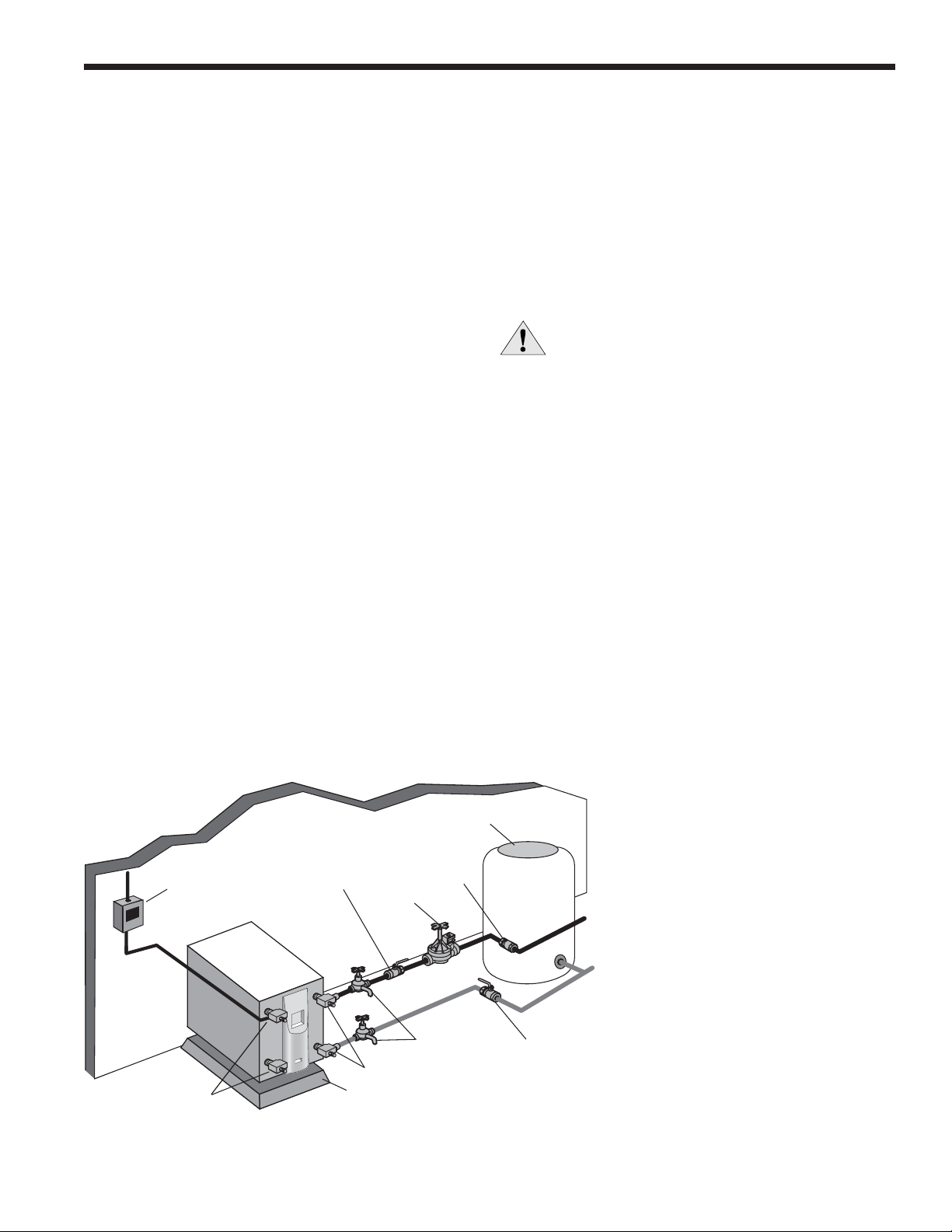
Process Water Applications
For process water applications, it is recommended that a secondary
load heat exchanger be installed to prevent corrosion to the unit’s
primary coaxial coil. In situations where scaling could be heavy
or where biological growth such as iron bacteria will be present, a
closed loop system is recommended. Over a period of time, ground
water unit heat exchanger coils may lose heat exchange capability
due to a buildup of mineral deposits. These can be cleaned only
by a qualified service mechanic as special pumping equipment
and solutions are required. Never use flexible hoses with a smaller
inside diameter than that of water connections.
Moving and Storage
Move units in the normal “Up” orientation as indicated by the labels
on the unit packaging. When the equipment is received, all items
should be carefully checked against the bill of lading to ensure
that all crates and cartons have been received in good condition.
Examine units for shipping damage, removing unit packaging if
necessary to properly inspect unit. Units in question should also be
internally inspected. If any damage is observed, the carrier should
make the proper notation on delivery receipt acknowledging the
damage. Units are to be stored in a location that provides adequate
protection from dirt, debris and moisture.
WARNING: To avoid equipment damage, do not leave
the system filled in a building without heat during
cold weather, unless adequate freeze protection
levels of antifreeze are used Heat exchangers do not
fully drain and will freeze unless protected, causing
permanent damage
Unit Location
Provide sufficient room to make water and electrical connections.
If the unit is located in a confined space, provisions must be made
for unit servicing. Locate the unit in an indoor area that allows easy
removal of the access panels and has enough space for service
personnel to perform maintenance or repair. These units are not
approved for outdoor installation and, therefore, must be installed
inside the structure being conditioned. Do not locate units in areas
subject to freezing conditions.
WARNING: Do not store or install units in corrosive
environments or in locations subject to temperature
or humidity extremes (eg attics, garages, rooftops,
etc) Corrosive conditions and high temperature
or humidity can significantly reduce performance,
reliability, and service life
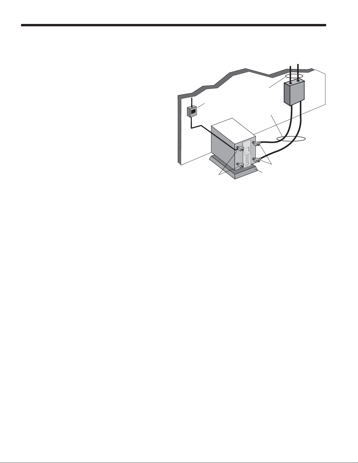
Mounting Units
Units should be mounted level on a vibration absorbing pad slightly
larger than the base to provide isolation between the unit and the
floor. It is not necessary to anchor the unit to the floor. Allow access
to the front, back, and side access panels for servicing.
Vibration Pad Mounting
General Installation Information

6
HS INSTALLATION MANUAL
General
HS water-to-water heat pumps may be successfully applied in a
wide range of residential and light commercial applications. It is
the responsibility of the system designer and installing contractor
to ensure that acceptable water quality is present and that all
applicable codes have been met in these installations.
Water Treatment
Do not use untreated or improperly treated water. Equipment
damage may occur. The use of improperly treated or untreated
water in this equipment may result in scaling, erosion, corrosion,
algae or slime. The services of a qualified water treatment
specialist should be engaged to determine what treatment, if any,
is required. The product warranty specifically excludes liability for
corrosion, erosion or deterioration of equipment.
The heat exchangers and water lines in the units are copper
or cupronickel tube. There may be other materials in the
building’s piping system that the designer may need to take into
consideration when deciding the parameters of the water quality.
If an antifreeze or water treatment solution is to be used, the
designer should confirm it does not have a detrimental effect on
the materials in the system.
Material Copper 90/10 Cupro-Nickel 316 Stainless Steel
pH Acidity/Alkalinity 7- 9 7 - 9 7 - 9
Scaling Calcium and Magnesium Carbonate (Total Hardness) less than 350 ppm (Total Hardness) less than 350 ppm (Total Hardness) less than 350 ppm
Hydrogen Sulfide Less than .5 ppm (rotten egg smell
appears at 0.5 PPM) 10 - 50 ppm Less than 1 ppm
Sulfates Less than 125 ppm Less than 125 ppm Less than 200 ppm
Chlorine Less than .5 ppm Less than .5 ppm Less than .5 ppm
Chlorides Less than 20 ppm Less than125 ppm Less than 300 ppm
Carbon Dioxide Less than 50 ppm 10 - 50 ppm 10- 50 ppm
Ammonia Less than 2 ppm Less than 2 ppm Less than 20 ppm
Ammonia Chloride Less than .5 ppm Less than .5 ppm Less than .5 ppm
Ammonia Nitrate Less than .5 ppm Less than .5 ppm Less than .5 ppm
Ammonia Hydroxide Less than .5 ppm Less than .5 ppm Less than .5 ppm
Ammonia Sulfate Less than .5 ppm Less than .5 ppm Less than .5 ppm
Total Dissolved Solids (TDS) Less than 1000 ppm 1000-1500 ppm 1000-1500 ppm
LSI Index +0.5 to -.05 +0.5 to -.05
Iron, Fe2+ (Ferrous)
Bacterial Iron Potential < .2 ppm < .2 ppm < .2 ppm
Iron Oxide Less than 1 ppm. Above this level
deposition will occur.
Less than 1 ppm. Above this level
deposition will occur.
Less than 1 ppm. Above this level
deposition will occur.
Suspended Solids Less than 10 ppm and filtered for max of
600 micron size
Less than 10 ppm and filtered for max of
600 micron size
Less than 10 ppm and filtered for max of
600 micron size
Threshold Velocity (Fresh Water) < 6 ft/sec < 6 ft/sec < 6 ft/sec
Grains = PPM divided by 17 • mg/l is equivalent to PPM 2/8/08
Corrosion
Erosion
Iron Fouling
(Biological Growth)
+0.5 to -.05
Contaminated Water
In applications where the water quality cannot be held to
prescribed limits, the use of a secondary or intermediate heat
exchanger is recommended to separate the unit from the
contaminated water.
The following table outlines the water quality guidelines for unit
heat exchangers. If these conditions are exceeded, a secondary
heat exchanger is required. Failure to supply a secondary heat
exchanger where needed will result in a warranty exclusion for
primary heat exchanger corrosion or failure.
Water Quality Guidelines
Water Quality

7
HS INSTALLATION MANUAL
refrigerant-to-water heat exchanger (See Pressure Drop Table for
water flow and pressure drop information). Normally about 3 GPM
flow rate per ton of cooling capacity (2.25 GPM per ton minimum) is
needed. Both source as well as load fluid piping must be at least as
large as the unit connections on the heat pump (larger on long runs).
Never use flexible hoses of a smaller inside diameter than that of
the water connection on the unit and limit hose length to 10 ft. per
connection. Check carefully for water leaks.
CAUTION: Water piping exposed to outside
temperature may be subject to freezing
Open Loop Well Water Systems
Always maintain water pressure in the heat exchanger by placing
water control valves at the outlet of the unit. Use a closed bladder
type expansion tank to minimize mineral deposits. Ensure proper
water flow through the unit by checking pressure drop across the
heat exchanger and comparing it to the figures in the pressure drop
table. Normally, about 2 GPM flow rate per ton of cooling capacity is
needed in open loop systems, (1.5 GPM per ton minimum if entering
source temperature is above 50°F [10°C].
Some water control valves draw their power directly from the
unit’s 24V transformer and can overload and possibly burn out the
transformer. Check total VA draw of the water valve(s) and ensure it
is under 40 VA.
Discharge water from a heat pump can be disposed of in various
ways depending on local building codes (i.e. recharge well, storm
sewer, drain field, adjacent stream or pond, etc.). Most local codes
restrict the use of sanitary sewer for disposal. Consult your local
building and zoning departments to ensure compliance in your area.
General
Each unit is equipped with captive FPT water connections to
eliminate ‘egg-shaping’ from use of a backup wrench. For making
the water connections to the unit, a Teflon tape thread sealant is
recommended to minimize internal fouling of the piping. Do not over
tighten connections. All supply and return water piping should be
insulated to prevent excess condensation from forming on the water
lines.
NOTE: Units are factory run-tested using propylene glycol
Prior to connecting piping to unit, thoroughly flush heat
exchangers
The piping installation should provide service personnel with the
ability to measure water temperatures and pressures. The water
lines should be routed so as not to interfere with access to the unit.
The use of a short length of high pressure hose with a swivel type
fitting may simplify the connections and prevent vibration. Optional
stainless steel hose kits are available as an accessory item.
Before final connection to the unit, the supply and return hose kits
must be connected, and the system flushed to remove dirt, piping
chips and other foreign material. Normally, a combination balancing
and close-off (ball) valve is installed at the return, and a rated gate or
ball valve is installed at the supply. The return valve can be adjusted
to obtain the proper water flow. The valves allow the unit to be
removed for servicing.
The proper water flow must be delivered to each unit whenever
the unit heats or cools. To assure proper flow, the use of pressure/
temperature ports is recommended to determine the flow rate.
These ports should be located adjacent to the supply and return
connections on the unit. The proper flow rate cannot be accurately
set without measuring the water pressure drop through the
Line Voltage
Disconnect
Load Liquid
Connections
Water Out
Water In
Rubber Bladder
Expansion Tank
Solenoid
Valve
Hayes Valve
Shut-off Valve
(to isolate solenoid
valve while acid
flushing)
Boiler Drains for
HX Flushing
Shut-off
Valve
Vibration Absorbing
Mesh or Air Pad
P/T Plugs
NOTE: Valves and boiler drains must be installed
so the heat exchanger can be acid flushed.
Typical Open Loop Installation
Field Connected Water Piping

8
HS INSTALLATION MANUAL
Earth Coupled Systems with Flow Center
Once piping is completed between the unit, flow center and the
earth loop, final purging and charging of the loop is needed. A flush
cart (at least a 1.5 HP or 1.12 kW pump) is needed to achieve
adequate flow velocity in the loop to purge air and dirt particles
from the loop itself. Antifreeze solution is used in most areas to
prevent freezing. Maintain the pH in the 7.6-8.2 range for final
charging.
Flush the system adequately to remove as much air as possible.
Then, pressurize the loop to a static pressure of 50-75 psi [345-
517 kPa]. This is normally adequate for good system operation.
Ensure that the flow center provides adequate flow through the
unit by checking pressure drop across the heat exchanger and
by comparing it to the figures shown in the Pressure Drop tables.
Usually, 3 GPM/ton [0.054 L/s/kW] L/s/kW or minimum 2.25 GPM/
ton [0.04 L/s/kW] of cooling capacity is needed in closed loop earth-
coupled applications
Typical Closed Loop Earth Coupled Installation
Field Connected Water Piping cont.
Line Voltage
Disconnect
Load Liquid
Connections
Vibration Absorbing
Mesh or Air Pad
P/T Plugs
Unit Connector Kits
with Insulation
Earth Coupled Loop
Piping with Insulation

9
HS INSTALLATION MANUAL
The HS018 and HS025 models can be equipped to provide
domestic hot water generation. An optional factory-installed hot
water generator coil may be provided with the HS040, HS050,
HS060, and HS075 to assist with this process.
NOTES:
1) Unions and valves must be installed so that acid flushing of the
heat exchanger is possible.
2) Route thermistor wires to HS. Remove yellow thermistor wires
on TB 3 and 4 from control box and connect thermistor wires
from geothermal storage tank. Set the pump sampling (PS) in
the set up of the control board to continuously (C) sampling
(reference Note 5 in the Wiring Schematic).
LOAD PUMP
HYDRONIC
LOAD
Source OUT
P/T PortsP/T Ports
Ball Valve
Dielectric
Unions
Dielectric
Unions
GeoSmart
Premium H Series - HS
NOTES:
* A 30 PSI pressure relief valve (Part No: SRV30) should be used in
hydronic applications.
** Vent valve or P/T port at highest point in return line prior to ball valve.
1-1/2˝
FPT
Expansion
Tank
Air
Vent
Pressure
Gauge
30 PSI
RELIEF VALVE
Air
Separator
FROM
DSH
TO
DSH
Back Flow Preventer /
Pressure Relief Valve
Source IN
GEO
STORAGE
TANK
PUMP
HOT COLD
DOMESTIC
Dip Tube
Ball Valve
Vent Valve/
P/T Port**
Suggested Domestic Water Heater Hookup
Hot Water Generator Connections
To maximize the benefits of the hot water generator a minimum
50-gallon water heater is recommended. For higher demand
applications, use an 80-gallon water heater as shown below or two
50-gallon water heaters connected in a series. Electric water heaters
are recommended. Make sure all local electrical and plumbing codes
are met for installing a hot water generator. The Premium H Series -
HS is not supplied with an internal circulator. A DPK5 kit will need to
be purchased to connect to the hot water generator. The DPK5 kit
is supplied with installation instructions, circulator, tank adaptor and
temperature limit switch. Be sure to burp (vent) the pump. Open the
screw 2 turns only in the end of the pump motor (if Grundfos® pumps
are used) to allow trapped air to be discharged and to ensure the
motor housing has been flooded.
Potable Water Systems

10
HS INSTALLATION MANUAL
Alternate Hot Water Installation with
Direct Coupling to a Double Wall Unit
P/T PortsP/T Ports
Ball Valve
Dielectric
Unions
Dielectric
Unions
GeoSmart
HS018 or HS025 (Heating Only)
with Double Wall Load Coax
GEOTANK
1-1/2˝
FPT
Ball Valve
HOT COLD
LOOP FIELD
FLOW CENTER
NOTES:
1) Unions and valves must be installed so that acid flushing of the
heat exchanger is possible.
2) Make sure there is not a check valve in the diptube of the tank.
3) Route thermistor wires to HS. Remove yellow thermistor wires
on TB 3 and 4 from control box and connect thermistor wires
from geothermal storage tank. Set the pump sampling (PS) in
the set up of the control board to continuously (C) sampling
(reference Note 5 in the Wiring Schematic).
Potable Water Systems cont.

11
HS INSTALLATION MANUAL
General guidelines are shown below for component selection
and design/installation criteria for the piping system. Local codes
supersede any recommendations in this manual.
Shut Off/Flow Regulation Valves
Use full port ball valves or gate valves for component isolation.
If valves are going to be used frequently, ball valves are
recommended. Globe valves are designed for flow regulation.
Always install globe valves in the correct direction (fluid should
enter through the lower body chamber).
Check valves
Swing check valves must be installed in the horizontal position
with the bonnet of the valve upright. Spring check valves can be
mounted in any position. A flow check valve is required to prevent
thermo-siphoning (or gravity flow) when the circulator pump is off or
when there are two circulators on the same system.
Storage (Buffer) Tank
A buffer tank is required for all hydronic heating systems using
Premium H Series - HS heat pumps. The tank should be sized to
provide 2 gallons of storage capacity for every one thousand Btuh’s
of nominal heat pump capacity.
Pressure Relief Valve
Most codes require the use of a pressure relief valve if a closed
loop heat source can be isolated by valves. Even if local code does
not require this device, GeoSmart recommends its installation. If
the pressure relief valve in the buffer tank is not already rated at
30 psi (207 kPa) maximum pressure, one must be installed. The
pressure relief valve should be tested at start up for operation.
Note that the waste pipe must be at least the same diameter as
the valve outlet (never reduce), and valves may not be added to
this pipe. The bottom of the pipe must terminate at least 6” (15 cm)
above the floor. If the piping is connected to a drain, there must be
an air gap.
Backflow Prevention Check Valves
Most codes require backflow prevention check valves. Note that
a single check valve is not equal to a backflow prevention check
valve. Even if local code does not require this device, GeoSmart
recommends its installation. This is particularly important if the
system will use antifreeze.
Pressure Reducing Valves or Feed Water Valves
This valve lowers the pressure from the make-up water line to the
system. Most are adjustable and directional. A “fast fill” valve is
required for initial filling of the system. Some have screens, which
must be cleaned after the initial filling. If there is a restriction in the
screen, the system could go to 0 psi (0 kPa), potentially causing
pumps(s) failure. A valve should be installed on each side of the
pressure reducing valve for servicing. Both valves should have
tags reading “Do not shut this valve under normal operation –
service valve only.”
Expansion Tanks
Expansion tanks are required on hydronic systems to help absorb
the pressure swings as the temperature in the system fluctuates.
Elbows/Tees
Long radius elbows or two 45° elbows will lower pressure drop.
Standard tees have a greater restriction on the “T” portion than
tees designed with angled outlet ports.
Antifreeze
Antifreeze is required if any of the piping system is located in areas
subject to freezing.
Dielectric Unions
Dielectric unions are recommended whenever connecting two
dissimilar metals to one and other to prevent electro-galvanic
corrosion.
When using the various types of hydronic heat distribution systems,
the temperature limits of the geothermal system must be a major
consideration. In new construction, the distribution system can
easily be designed with the temperature limits in mind. In retrofits,
care must be taken to address the operating temperature limits
of the existing distribution system. The maximum storage tank
temperature for the Premium H Series - HS is 130°F (54.4°C).
Typical in floor radiant systems require much lower temperatures,
typically 100°-115°F, which is ideal for the Premium H Series - HS.
Hydronic Section

12
HS INSTALLATION MANUAL
QT
Thermostat
Open the screw 2 turns only in the end of the pump motor (if
Grundfos® pumps are used) to allow trapped air to be discharged
and to ensure the motor housing has been flooded.
Route thermistor wires to HS. Remove yellow thermistor wires on
TB 3 and 4 from control box and connect thermistor wires from
geothermal storage tank. Set the pump sampling (PS) in the set up
of the control board to continuously (C) sampling (reference Note 5
in the Residential Reversible Wiring Schematic).
Adequate rate of flow (GPM) is very important to system
performance and long term reliability. Follow the guidelines for
recommended flow and pipe sizing in the HS recommendations
table.
GeoSmart Geothermal Storage Tank Thermostat and
Thermistor
Yellow Thermistor Wires Connected to TB (3 and 4) on HS
Control Board
HS
LOAD PUMP
HYDRONIC
LOAD
Source OUT
P/T PortsP/T Ports
Ball Valve
Dielectric
Unions
Dielectric
Unions
GeoSmart
Premium H Series - HS
NOTES:
* A 30 PSI pressure relief valve (Part No: SRV30) should be used in
hydronic applications.
** Vent valve or P/T port at highest point in return line prior to ball valve.
1-1/2˝
FPT
Expansion
Tank
Air
Vent
Pressure
Gauge
30 PSI
RELIEF VALVE
Air
Separator
FROM
DSH
TO
DSH
Back Flow Preventer /
Pressure Relief Valve
Source IN
GEO
STORAGE
TANK
PUMP
HOT COLD
DOMESTIC
Dip Tube
Ball Valve
Vent Valve/
P/T Port**
Hydronic Section cont.

13
HS INSTALLATION MANUAL
0
5
10
15
20
25
30
35
0 5 10 15 20 25 30 35
Feet of Head
GPM
UP26-99F
UP26-64BF
UP15-42B7
0
10
20
30
40
50
60
70
0 5 10 15 20 25 30 35
Feet of Head
GPM
UP26-99F (2 pumps)
UP26-64BF (2pumps)
Water Connection Kits (Field Installed)
Water connection kits have been designed to facilitate load-side
and loop-side water connections.
Earth Loop Pump Kit (Field Installed)
A specially designed one or two-pump module provides all liquid
flow, fill and connection requirements for independent single unit
systems (230/1/60 only). The one-pump module is capable of 20
feet of head at 16.0 GPM, while the two-pump module is capable of
40 feet of head at 16.0 GPM.
Hot Water Generator (Factory Installed, HS040, HS050,
HS060, and HS075 Only)
An optional heat reclaiming hot water generator coil constructed of
vented double-wall copper construction suitable for potable water
is available. The coil is factory mounted inside the unit. A DPK5
pump kit is required (field installed), which includes a DHW tank
connection and a temperature limit pump shutoff.
Load-side Pump Kit (Field Installed)
Four (4) load pump kits are available to provide all liquid flow
requirements for independent single unit systems (230/1/60 only).
GeoSmart part number 24P501A04 (Grundfos UP15-42B7) and
EWPK2 (Grundfos UP26-64BF) are bronze body pumps. Bronze
body pumps should be used when water conditions exist that are
not compatible with cast iron or for applications such as domestic
water heating. GeoSmart part number EWPK1 and EWPK3 come
with a cast iron body pump (Grundfos UP26-99F) that can be used
for hydronic heating applications.
Calculate the system pressure drop then refer to the pump curves
to select the proper pump. All four of the GeoSmart pump kits can
be used for hydronic heating applications as long as they meet the
flow requirements. If the flow requirements are outside the pump
curve, an alternate pump will need to be obtained to maintain the
necessary flow.
GeoStartTM
The optional GeoStart single phase soft starter will reduce the
normal start current (LRA) by 60-70%. This allows the heat
pump to go off-grid. Using GeoStart also provides a substantial
reduction in light flicker, reduces start-up noise, and improves the
compressor’s start behavior. GeoStart is available in a field retrofit
kit (GeoSmart part number IS60RKL or IS60RKS) or as a factory
installed option for all G Series, H Series, and QT units.
NOTE: Never use piping smaller than 1 inch. Limit length of pipe to
50 feet or less.
Type L Copper Tube
GPM 3/4 1 1-1/4 1-1/2 2
21.5
33.2
45.5 1.4
58.5 2.1
62.9 1.1
73.9 1.4
85.0 1.8
96.1 2.3 0.9
10 7.5 2.8 1.1
12 3.9 1.6
14 5.2 2.1
16 6.6 2.7
18 8.2 3.4
20 10.0 4.1 1.1
22 5.0 1.3
25 6.3 1.6
30 2.2
35 2.9
40 3.8
45 4.7
50 5.7
Type L Copper Pressure Loss
Ft of Hd per 100 ft
NOTE: Standard piping practice limits pressure drop to 4 feet of hd
per 100 feet in 2 inch and larger pipe.
Two Pump Curve: UP26-64BF and UP26-99F
Single Pump Curve: UP15-42B7, UP26-64BF, and UP26-99F
Accessories and Options

14
HS INSTALLATION MANUAL
3
0
°
3
0
°
To Geo 59˝ Dip Tube
w/1˝ x 3˝ Nipple
Approx. 1˝
T & P
VALVE
From Geo
1˝ x 3˝ Nipple
PRIMARY ANODE
39˝ - 80 Gallon
42˝ - 119 Gallon
3/4˝ COLD INLET
52˝ DIP TUBE
3/4˝ HOT OUTLET
w/14˝ SECONDARY ANODE
HEIGHT
Optional “To Geo”
Connection Shipped with
1-1/2˝ Pipe Plug Installed
Element Location
Yellow Wire attached
to Thermistor or Thermostat
for Top Exit
Lower Sensor Thermistor (12P541-01)
to be used by Water to Water Units
Optional “From Geo” Connection
Shipped with 1-1/2˝ Pipe Plug Installed
DIAMETER
8˝
5-1/4˝
35-3/4˝
Lower Thermostat to be used
with QT units
DRAIN VALVE
MODEL
NUMBER
GALLON
CAPACITY
ELEMENT
WATTAGE
(240 VOLT)
NUMBER
OF
ELEMENTS
R
VALUE
DIMENSIONS IN INCHES APPROX
SHIPPING
WEIGHT (lbs)
HEIGHT DIAMETER
GEO-STORAGE-80 80 4500 1 16 63-1/4 24 204
GEO-STORAGE-120 119 4500 1 16 63-1/4 28 311
Geo Storage Tank Dimensions
Accessories and Options cont.

15
HS INSTALLATION MANUAL
HS Control Box
Load Pump Fuse Block
(Residential Only)
Transformer
Run Capacitor (Single
Phase Only)
Ground Lug
Load Pump Relay
Terminal Board
Power Block
Terminal Power Strip
Optional GeoStartTM
(Single Phase Only)
Compressor Contactor
Power Block
GeoStart Only
Source Pump Fuse Block
(Residential Only)
Source Pump Relay
Reversing Valve Relay
(Reversible Units Only)
NOTES: All fuses type “D” time delay (or HACR circuit breaker in USA).
Source pump amps shown are for up to a 1/2 HP pump.
Load pumps amps shown are for small circulators.
*LRA with optional GeoStart installed (208-230/1/60).
Model Rated
Voltage
Voltage
Min/Max
Compressor Load
Pump
Source
Pump
Total Unit
FLA
Min Ckt
Amp
Maximum
Fuse/HACR
RLA LRA LRA*
018 208-230/60/1 197/254 10.3 51.0 17.9 1.8 5.4 17.5 20.1 30
025
208-230/60/1 197/254 13.5 61.0 21.4 1.8 5.4 20.7 24.1 35
265/60/1 239/292 10.9 58.0 - - - 10.9 13.6 20
460/60/3 414/506 4.5 27.0 - - - 4.5 5.6 10
040
208-230/60/1 197/254 20.0 115.0 40.3 1.8 5.4 27.2 32.2 50
208-230/60/3 197/254 12.8 95.0 - - - 12.8 16.0 25
460/60/3 414/506 6.4 45.0 - - - 6.4 8.0 10
575/60/3 518/632 5.4 38.0 - - - 5.4 6.8 10
050
208-230/60/1 197/254 26.4 134.0 46.9 1.8 5.4 33.6 40.2 60
265/60/1 239/292 19.9 130.0 - - - 19.9 24.9 40
208-230/60/3 197/254 16.0 110.0 - - - 16.0 20.0 35
460/60/3 414/506 7.8 52.0 - - - 7.8 9.8 15
575/60/3 518/632 5.7 38.9 - - - 5.7 7.1 10
060
208-230/60/1 197/254 30.1 145.0 50.8 1.8 5.4 37.3 44.8 70
208-230/60/3 197/254 17.3 120.0 - - - 17.3 120.0 35
460/60/3 414/506 9.6 70.0 - - - 9.6 70.0 20
575/60/3 518/632 8.0 53.0 - - - 8.0 53.0 15
075
208-230/60/1 197/254 26.9 145.0 50.8 1.8 5.4 34.1 40.8 60
208-230/60/3 197/254 22.4 190.0 - - - 22.4 28.0 50
460/60/3 414/506 12.2 87.0 - - - 12.2 15.3 25
575/60/3 518/632 9.6 62.0 - - - 9.6 12.0 20
7/22/2009
Electrical Data

16
HS INSTALLATION MANUAL
208 Volt Operation
All 208-230 volt units are factory wired for 230 volt operation. To
convert the unit from a 230V unit to a 208V unit follow these steps:
1. Remove the blue transformer wire from terminal L2 on the
compressor contactor and secure the wire taking care to
insulate the end with electrical tape.
2. Locate the red transformer wire and connect it to the L2 terminal
of the compressor contactor.
Electrical
Be sure the available power is the same voltage and phase as that
shown on the unit serial plate. Line and low voltage wiring must be
done in accordance with local codes or the National Electric Code,
whichever is applicable. Refer to the Electrical Data table for wire
and fuse or circuit breaker sizing information.
Flow Center Pump Connection (208-230/60/1)
Two fuse internal terminal block connections with 1/4-inch spade
connectors are provided; one for the load pump and one for the
source pump. The source pump directly connects to the fuse
terminal block for the source pump. The load pump directly
connects to the fuse terminal block for the load pump.
HS Control Box Relocation
The HS control box can be installed on the rear of the unit. To
relocate the control box, follow the procedures below.
1. Remove all power sources to the unit.
2. Remove the unit’s top panel.
3. Cut all plastic wire ties to the following:
a) High pressure switch (black wires)
b) Low pressure switch (blue wires)
c) Freeze sensing (yellow wires)
d) Load temperature sensor (black wires)
e) Compressor wires
4. Remove the four screws from the control box.
5. Relocate the control box to opposite end of the unit.
6. Using the screws removed in step 4 above, reattach the control
box.
7. Secure all wires so they do not come in contact with refrigerant
lines.
8. Replace the top of the unit.
9. Replace both access panels.
10. Reapply power sources.
NOTE: If geothermal storage tank is used, connect yellow
thermistor wires from the bottom access panel of the tank to spade
connectors 3 and 4 on the terminal block.
For all HS 208/230 volt single-phase units, the circulator wiring is as shown in the illustrations below. The internal relay and fusing allow
for external pumps no larger than .5 horsepower. The external loop pump connections mentioned in this manual include a dedicated flow
center for each unit as well as an HS unit connected to a G Series; “P” or an “E” series unit containing a microprocessor.
Load Circulator Wiring
HS CONTROL BOX
LOAD
CIRCULATOR
PUMP
TRANSFORMER
LOW VOLTAGE
TERMINAL STRIP
FUSE
BLOCKS
LOW VOLTAGE
THERMOSTAT
CONNECTIONS
COMPRESSOR
CONTACTOR
T1 T2
L1 L2
CAPACITOR
TRANSFORMER
LOW VOLTAGE
TERMINAL STRIP
FUSE
BLOCKS
LOW VOLTAGE
THERMOSTAT
CONNECTIONS
COMPRESSOR
CONTACTOR
T1 T2
L1 L2
CAPACITOR
FLOW CENTER
HS CONTROL BOX
Dedicated Flow Center Wiring
Electrical Data cont.
Wiring Schematics

17
HS INSTALLATION MANUAL
TRANSFORMER
LOW VOLTAGE
TERMINAL STRIP
FUSE
BLOCKS
LOW VOLTAGE
THERMOSTAT
CONNECTIONS
COMPRESSOR
CONTACTOR
T1 T2
L1 L2
CAPACITOR
P2
SHUT
DOWN
C
Not
Used
C
P1
G
W
O
R
C
Y1
Y2
LO
G SERIES
CONTROL
BOX
13P003B RELAY
(FIELD SUPPLIED)
SL1IN
SL1OUT
HS CONTROL BOX
Multiple Units on a Single Flow Center Wiring
Wiring Schematics cont.

18
HS INSTALLATION MANUAL
HS Heating Only - 208-230/60/1
Transformer
NOTE 1
Red
208V
Black
Com
Compressor
Unit
Power Supply
CC
T1
L1
T2
Tan
Brown
Blue
G
C
R
S
BlackRed
Blue
Factory low voltage wiring
Legend
Switch - High pressure
Switch - Low pressure
Relay coil
Field wire lug
Ground
Relay Contacts -
N.O., N.C.
Polarized connector
Notes:
Factory line voltage wiring
Field low voltage wiring
Field line voltage wiring
Optional block
Quick connect terminal
Screw terminal - field connection
CC -
-
HP -
LP -
LPR -
Compressor contactor
High pressure switch
Low pressure switch
Load Pump Relay
L1
1
3
2
PCapacitor
24V
Microprocessor Control
TEST
PIN
HP HP C C CG HI L O CL P LPR
CC
HP
LP
Black/
White
Blk/Wht
Violet
Black
Black
White/Blue
White/Blue
Red
LPR
T
T
RT
EL T
Orange
X1ELT ELTRTRT
X2 X1
X1ELT ELT RTRT
X2X1
RV Reversing Valve output
ELT -Entering Load Side Water Temperature
Green/Yellow
TThermistor
P1
P2
P3
X3
X3
X3
X3
LPR
Interface Panel
Black
Black
Yellow
Yellow
Violet
Violet
Orange
Orange
Gray
Gray
1
2
3
4
5
6
7
8
TB
1
1
G
Load
Pump
External
X2
X2
PS1
RV RVG
RT -Refrigerant Liquid line Temperature
SI
SI -Slave Input relay
RCY1 OX1
G
External
SI
RC -Reversing Valve Coil
Fuse
Cap
9
10
11
12
1. Taped and wire tied off
Not Used
Not Used
Not Used
Not Used
Not Used
Green/Yellow
Yellow
24 V
B C D
L2 L2L1L1
T1T1 T2T2
LFB SFB
LFB -
SFB -
Load Pump Fuse Block
Source Pump Fuse Block
NOTE 2
2. 3AG 10 Amp fuse
Blue/Wht
Brown/Wht
Brown/Blk
Red
Black
Orange
Black/Gry
Violet
Black/Wht
L2
208-230/60/1
Source
Pump
MODE
3. For cycle load pump with a geo storage
tank. Remove the orange wire from the LPR
relay coil and install a jumper between the
LPR relay coil and the comp contactor coil
as shown in the schematic above.
Note 3
Blue
230V
04/02/09
Wiring Schematics - Residential

19
HS INSTALLATION MANUAL
HS Reversible with GeoStart - 208-230/60/1
Transformer
NOTE 1
Red
208 V
Compressor
Unit
Power Supply
CC
T1
L1
T2
Brown
G
C
R
S
Blue
24V
Microprocessor Control
TEST
PIN
HP HP C C CG HI LO CL P LPR
C C CG HI LO CL P LPR
HP
LP
Black/
White
Blk/Wht
Violet
White/Blue
White/Blue
LPR
T
RT
Orange
X1 E LTELTRTRT
X2X1
X1 ELTELTRTRT
X2 X1
Green/Yellow
P1
P2
P3
X3
X3
X3
X3
LPR
Interface Panel
Black
Black
Yellow
Violet
Violet
Orange
Orange
Gray
Gray
1
2
3
4
5
6
7
8
TB
1
1
G
Load
Pump
External
X2
X2
PS1
RV RVG
SIR
RCY1 OX1
G
External
SI
Cap
9
10
11
12
Not Used
Not Used
Not Used
Green/Yellow
Yellow
24 V
B C D
L2 L2L1L1
T1T1 T2T2
LFB SFB
NOTE 2
Brown/Wht
Brown/Blk
Red
Black
Orange
Black/Gry
Black/Wht
L2
208-230/60/1
Source
Pump
MODE
RVR
RVR
T
RT
Yellow
RC
NOTE 3
RVR
T
EL T
Org/Wht Org/Blk
Blue Blue
Black Black
Yellow
Yellow
Violet
Black/Org
Org/Gry
Org/Brn
HP HP
Black
Black
Red
Org/Grn Orange
NOTE 4
Note 5
CC
Black
Com
Blue/Wht
Blue
Blue
230V
Black
Tan
Black
Run Winding
Active
Start
Common
GeoStart
Pink
Black
2
1
PB
RedRed
Blue
Factory low voltage wiring
Legend
Switch - High pressure
Switch - Low pressure
Relay coil
Field wire lug
Ground
Relay Contacts -
N.O., N.C.
Polarized connector
Notes:
Factory line voltage wiring
Field low voltage wiring
Field line voltage wiring
Optional block
Quick connect terminal
Screw terminal - field connection
Compressor Contactor
High Pressure Switch
Low Pressure Switch
Load Pump Relay Contacts
L1
1
3
2
PCapacitor
Reversing Valve Output
Entering Load Side Water Temperature
TThermistor
Refrigerant Liquid Line Temperature
Slave Input Relay
Reversing Valve Coil
Fuse
1. Taped and wire tied off
Load Pump Fuse Block
Source Pump Fuse Block
2. 3AG 10 Amp fuse
3. Move jumper wire to 5 and 6 for reversible
secondary unit.
4. Black Thermistor - Source Coax Blue
Thermistor - Load Coax
5. For cycle load pump with a geo storage tank.
Remove the orange wire from the LPR relay coil
and install a jumper between the LPR relay coil
and the comp contactor coil as shown in the
schematic above.
CC -
-
HP -
LP -
LPR -
RV
ELT -
RT -
SIR -
RC -
LFB -
SFB -
RVR -Reversing Valve Relay
04/02/09
Wiring Schematics - Residential cont.

20
HS INSTALLATION MANUAL
HS Heating Only - 208-230/60/3
Wiring Schematic - Commercial
Transformer
Blue
230 V
NOTE 1
Red
208 V
Black
Com
Factory low voltage wiring
Legend
Switch - High pressure
Switch - Low pressure
Relay coil
Field wire lug
Ground
Relay Contacts -
N.O., N.C.
Polarized connector
Notes:
Factory line voltage wiring
Field low voltage wiring
Field line voltage wiring
Optional block
Quick connect terminal
Screw terminal -
field connection
CC -
HP -
LP -
LPR -
Compressor contactor
High pressure switch
Low pressure switch
Load Pump Relay
L1
1
3
2
PCapacitor
24V
Microprocessor Control
TEST
PIN
HP HP CC CG HI LO CLP LPR
CC
HP
LP
Black/
White
Blk/Wht
Violet
Black
White/Blue
White/Blue
T
T
RT
EL T
Orange
X1E LTELT RTRT
X2X1
X 1 E LTELTRTRT
X2X1
RV Reversing Valve output
ELT - Entering Load Side Water Temperature
Green/Yellow
TThermistor
P1
P2
P3
X 3
X3
X3
X3
LPR
Interface Panel
Black
Black
Yellow
Yellow
Violet
Violet
Orange
Orange
Gray
Gray
1
2
3
4
5
6
7
8
TB
1
1
X2
X2
PS1
RV RVG
RT - Refrigerant Liquid line Temperature
SI
SI - Slave Input relay
RCY1 OX1
SI
RC - Reversing Valve Coil
Fuse
9
10
11
12
1. Taped and wire tied off
Not Used
Not Used
Not Used
Not Used
Not Used
Green/Yellow
Yellow
24 V
B C D
LFB -
SFB -
Load Pump Fuse Block
Source Pump Fuse Block
Red
Black
Orange
Black/Gry
Violet
Black/Wht
MODE
Compressor
G
CC
T1
L1
T2
L2
T3
L3
T1
T2
T3
Blue Black
Unit
Power Supply
Red
208-230/60/3
Black
Red
97P798-08 04/02/09
Table of contents
Other GeoSmart Heat Pump manuals
Popular Heat Pump manuals by other brands

Goodman
Goodman CPLE090 Installation & operating instructions

Pentair
Pentair INVERTEMP IVTP-1M-LT Installation and operating manual

Fedders
Fedders CH1018BBD Installation, operation and maintenance

Dimplex
Dimplex SI 50TUR Installation and operating instruction

Panasonic
Panasonic S-250WX2E5 Technical data

Amana
Amana RHE48C2A Specification sheet