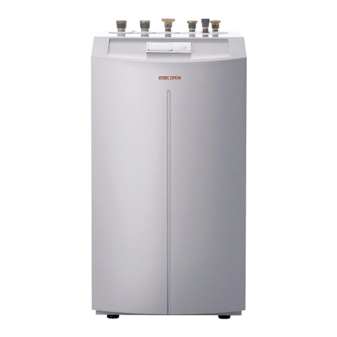
1 General
These installation instructions are for contrac-
tors. The heat pump installation also requires
the operating instructions of the heat pump
manager WPM.
The heating system heat pumps and the WPM
represent one function unit. Consequently,
their instructions are matched to each other.
Subject to the relevant system, observe the
installation instructions of the components of
which the system comprises.
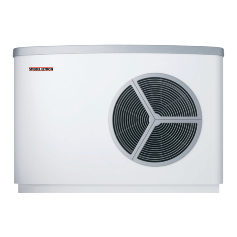
1.1 Equipment description
• Forfullyautomaticheatingofheatingwater
to a flow temperature of 60 °C.
• Suitableforunderoorheatingandradiator
heating systems; preferred are low tempe-
rature heating systems, as these achieve
higher performance factors.
• Extractsenergyfromtheambientair(out-
side)
even at outside temperatures as low as –20
°C.
• Comprisesallcomponentsrequiredforits
function and all safety equipment.
• Centralcontroloftheheatingsystemand
safety functions through the WPM heat
pump manager (required accessory, part no.
see section 1.6).
• Corrosion-protected,externalcasingmade
from hot-dipped galvanised sheet steel plus
stove enamelled finish.
• Compactdesign,thereforemodestspace
requirementsforinteriororexteriorinstal-
lations.
• Testsymbolofindependenttestbodies
(see type plate).
• Filledwithnon-combustiblesafetyrefrige-
rant R407C.
1.2 Function
Heatisextractedfromoutsideairwithtem-
peratures ranging from + 30 °C to –20 °C by
theheatexchangerontheairside(evapo-
rator). Heating water is heated in the heat
exchangeronthewaterside(condenser)to
owtemperaturelevelsbythisextractedheat
and added heat from the electrical power
used by the compressor. At air temperatures
belowapprox.+7°C,thehumidityintheair
condenses as hair-frost on the evaporator fins.
This hair-frost is automatically removed. Any
water created from this defrosting is caught
in the defrost basin and drained off via a hose
(Fig. 7 and 8).
The fan is switched OFF and the heat
pump circuit is reversed to enable
the defrost phase. The energy required for
defrosting is drawn from the buffer cylinder.
For that reason, operation without a buffer
cylinder is not permissible, otherwise unfa-
vourable conditions could lead to the heating
water freezing up.
The heat pump automatically reverts to heat-
ing mode at the end of the defrost phase.
1.3 Correct operation
Theheatpumpisdesignedforextractingen-
ergy from the air and for
utilising this energy in water-based
heating systems within the stated operating
temperature range.
1.4 Incorrect operation
The installation location must be prepared by
your contractor in line with section 3.2. Never
operate the heat pump in areas at risk from
explosionsoroutsidethestatedoperating
temperature range.
1.5 Regulations and standards
Observe the following regulations and stan-
dards during assembly and installation.
On the water side:
DIN EN 12828 Safety equipment for hot water
heating systems
DIN 1988: Technical rules for DHW installations
TRD721:Safetyequipmenttopreventexcess
pressure - safety valves
On the electrical side:
DIN VDE 0100: Regulations for the installation
of HV systems with rated voltages up to 1000 V.
VDE 0701: Regulations regarding the repair,
modification and testing of used electrical
equipment.
VDE 0298-4:
TAB: Technical connection conditions for con-
nections to the LV mains.
On the refrigerant side:
EN 378: Safety and environmental require-
ments
DIN 7003: (draft)
General:
Collation of technical requirements for boiler
rooms, e.g. boiler room guidelines or nation-
al/local Building Regulations, commercial and
fire as well as emission control regulations
and requirements.
TA Lärm: Technical instructions to protect
against noise emissions
Installation instructions for contractors
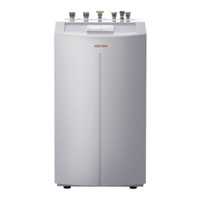
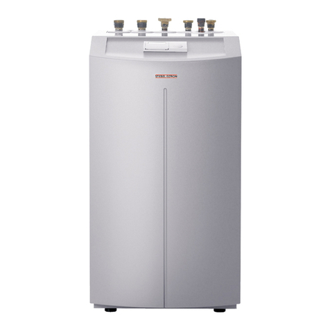
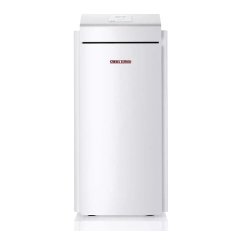
1.6 Standard delivery and accessories
Part no.
Standard delivery – external installation
–Base unit
–Accessories (comprising the casing). 07 44 13
Standard delivery – internal installation
– Base unit
– Accessories (comprising the casing) 07 44 12
Accessories – internal installation
Air hose with thermal insulation, 3 m 16 80 80
Air hose with thermal insulation, 4 m 16 80 81
Hose connection plate 00 34 78
Condensate pump PK 9 18 21 38
Accessories – external installation
Sound insulation accessories 18 53 25
Accessories – external and internal inst. (required)
Cylinder SBP 200 E 18 54 58
Cylinder SBP 400 E 22 08 24
Cylinder SBP 700 E 18 54 59
Cylinder SBP 700 E SOL 18 54 60
Heat pump manager with wall mounting enclosure, WPMW II 18 54 50
Heat pump manager as control panel mounted version, WPMS II 18 54 51
Special accessories – external and internal installation
Mixermoduleascontrolpanelmountedversion,MSMS 07 45 18
PressurehoseG1¼”x1m(DN32) 07 44 14
PressurehoseG1¼”x2m(DN32) 18 20 19
PressurehoseG1¼”x5m(DN32) 18 20 20
PressurehoseG1¼”x1m(DN32)fortrimming 18 56 47
Hose fittings for pressure hose G 1¼” (DN32) 07 06 92
Heat pump Compact Installation WPKI 5 22 08 30
UP kit 32 - 60 (for WPKI 5) 07 06 30
UP kit 32 - 80 (for WPKI 5) 07 06 31
Remote control for heating system FE 7 18 55 79
Contact sensor AVF 6 16 53 41
Immersion sensor TF 6 16 53 42


